EP1494860B1 - Procede d'entrainement d'une unite d'impression - Google Patents
Procede d'entrainement d'une unite d'impression Download PDFInfo
- Publication number
- EP1494860B1 EP1494860B1 EP03722204A EP03722204A EP1494860B1 EP 1494860 B1 EP1494860 B1 EP 1494860B1 EP 03722204 A EP03722204 A EP 03722204A EP 03722204 A EP03722204 A EP 03722204A EP 1494860 B1 EP1494860 B1 EP 1494860B1
- Authority
- EP
- European Patent Office
- Prior art keywords
- cylinder
- drive motor
- speed
- cylinders
- printing
- Prior art date
- Legal status (The legal status is an assumption and is not a legal conclusion. Google has not performed a legal analysis and makes no representation as to the accuracy of the status listed.)
- Expired - Lifetime
Links
- 238000000034 method Methods 0.000 title claims abstract description 33
- 238000004519 manufacturing process Methods 0.000 claims description 24
- 230000005540 biological transmission Effects 0.000 claims description 9
- 230000008859 change Effects 0.000 claims description 5
- 238000012512 characterization method Methods 0.000 claims 1
- 230000002596 correlated effect Effects 0.000 claims 1
- 230000002093 peripheral effect Effects 0.000 description 66
- 238000012546 transfer Methods 0.000 description 35
- 230000001172 regenerating effect Effects 0.000 description 9
- 238000013519 translation Methods 0.000 description 6
- 230000014616 translation Effects 0.000 description 6
- 230000001105 regulatory effect Effects 0.000 description 5
- 238000005096 rolling process Methods 0.000 description 5
- 239000000758 substrate Substances 0.000 description 5
- 230000001419 dependent effect Effects 0.000 description 4
- 230000008569 process Effects 0.000 description 4
- 238000013461 design Methods 0.000 description 3
- 230000001737 promoting effect Effects 0.000 description 3
- 230000004044 response Effects 0.000 description 3
- 230000002123 temporal effect Effects 0.000 description 3
- 229910000831 Steel Inorganic materials 0.000 description 2
- 230000007935 neutral effect Effects 0.000 description 2
- 230000002441 reversible effect Effects 0.000 description 2
- 239000010959 steel Substances 0.000 description 2
- 238000003860 storage Methods 0.000 description 2
- 208000034656 Contusions Diseases 0.000 description 1
- 238000010521 absorption reaction Methods 0.000 description 1
- 230000002238 attenuated effect Effects 0.000 description 1
- 230000008901 benefit Effects 0.000 description 1
- 208000034526 bruise Diseases 0.000 description 1
- 238000004891 communication Methods 0.000 description 1
- 230000008878 coupling Effects 0.000 description 1
- 238000010168 coupling process Methods 0.000 description 1
- 238000005859 coupling reaction Methods 0.000 description 1
- 230000003247 decreasing effect Effects 0.000 description 1
- 238000011156 evaluation Methods 0.000 description 1
- 239000000284 extract Substances 0.000 description 1
- 238000012423 maintenance Methods 0.000 description 1
- 238000005259 measurement Methods 0.000 description 1
- 238000012545 processing Methods 0.000 description 1
- 230000009467 reduction Effects 0.000 description 1
- 230000001360 synchronised effect Effects 0.000 description 1
Images

Classifications
-
- B—PERFORMING OPERATIONS; TRANSPORTING
- B41—PRINTING; LINING MACHINES; TYPEWRITERS; STAMPS
- B41F—PRINTING MACHINES OR PRESSES
- B41F13/00—Common details of rotary presses or machines
- B41F13/004—Electric or hydraulic features of drives
- B41F13/0045—Electric driving devices
-
- B—PERFORMING OPERATIONS; TRANSPORTING
- B41—PRINTING; LINING MACHINES; TYPEWRITERS; STAMPS
- B41P—INDEXING SCHEME RELATING TO PRINTING, LINING MACHINES, TYPEWRITERS, AND TO STAMPS
- B41P2213/00—Arrangements for actuating or driving printing presses; Auxiliary devices or processes
- B41P2213/70—Driving devices associated with particular installations or situations
- B41P2213/73—Driving devices for multicolour presses
- B41P2213/734—Driving devices for multicolour presses each printing unit being driven by its own electric motor, i.e. electric shaft
Definitions
- the invention relates to a method for driving a printing unit according to the preamble of claim 1.
- WO 00/41887 A1 is a friction gear of process-related friction cylinders a compensating friction gear in the form of bearer rings reverse radii ratio superimposed.
- the normal force between the juxtaposed cylinders is set in such a manner that an amount of difference in power consumption of the motors driving the cylinders is minimum.
- the DE 195 27 199 A1 shows a drive of a printing unit, wherein a forme cylinder is driven in response to a contact of the printing plate with a counter-pressure cylinder with different peripheral speeds.
- a circumferential speed different from the impression cylinder is present in a phase of the cylinder revolution in which there is no pressure contact between the impression cylinder and the impression cylinder.
- the invention has for its object to provide a method for driving a printing unit, wherein a sufficiently good handling of the printing cylinder is largely independent of the pitch or the number of pressure points or the elevator thickness or the elevator type.
- the achievable with the present invention consist in particular in that a sufficiently good processing of the printing cylinder takes place, which is largely independent of Anstelltik and / or the number of active pressure points, the elevator strength and / or the type or manufacturer of the elevator.
- the print quality is not or only slightly deteriorated.
- a suitable, defined difference in the peripheral speed can be determined for different operating modes and / or elevators, eg. B. stored in a storage unit and depending on the mode / elevator imposed during production and obtained.
- the o. G. Control is particularly useful in printing units, with multiple transfer cylinders with so-called. Satellite cylinders form pressure points, such. B. in 5-cylinder pressure units, 9-cylinder or 10-Zylinderatellitendruckappelen.
- the scheme is also suitable for pressure units with successive rolling bearer rings, in which case a slip between the bearer rings is permitted within certain limits (see below).
- the satellite cylinder In order to maintain a desired print quality, simultaneously with the minimization of the regenerative or motor power on the satellite cylinder selectable lower or upper limits for the deviation of the rotational speed or the peripheral speed not fallen below or exceeded by the peripheral speed of the co-operating transfer cylinder. Within these limits, the satellite cylinder is driven at its minimum absolute power (regenerative or motor). These limits are different for different substrates, for different printing methods and different quality requirements each selectable and are z. For newspaper printing at between ⁇ 0.01% to ⁇ 0.05% deviation from the production or peripheral speed of the cooperating cylinders.
- This control is advantageous for printing units whose cylinders are driven in groups or individually by a plurality of mechanically uncoupled drive motors: for example for 9 or 10-cylinder satellite pressure units with one drive motor per cylinder, for 9 or 10-cylinder satellite pressure units with one drive motor per form cylinder Transfer cylinder pair and the satellite cylinder (s) or even for 9 or 10-Zylinderatelliten horradosen each having a drive motor for a group of forme cylinder-transfer cylinder pairs.
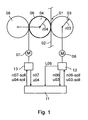
- a rotary printing machine has a printing point 01 with two in a print-on position via a web 02, z. B. a printing substrate 02, in particular a paper web 02, cooperating cylinders 03; 04 on.
- the cylinders 03; 04 are formed in the example without bearer rings and form by means of their mutually rolling lateral surfaces a friction gear.
- the first cylinder 03 is as impression cylinder 03, z. B. as a steel cylinder 03, and is directly or indirectly via a drive motor 06, but independently of the second cylinder 04, z. B. a transfer cylinder 04 or a plate cylinder 04 in high-pressure or flexographic printing, driven.
- the example designed as a transfer cylinder 04 second cylinder 04 is also directly or indirectly, for example via a not shown gear, z.
- the transfer cylinder 04 may individually or together with a cooperating with this third cylinder 08, z. B. a forme cylinder 08, or a color and, if necessary, dampening unit, not shown.
- the transfer cylinder 04 can be driven together with the forme cylinder 08 by means of the drive motor 07 (schematically in FIG Fig. 1 ).
- the second cylinder 04 has on its lateral surface an elevator 09, z.
- an elevator 09, z As a blanket 09, a blanket 09 or a plate 09, through which the ink is applied to the paper web 02.
- the impression cylinder 03 with a radius r03 and the transfer cylinder 04 with a radius r04 as the cylinder 03; 04 executed with so-called.
- Double circumference ie with a circumference, which two standing or lying print pages, z. B. newspaper pages, corresponds.
- the forme cylinder 08 has this scope here.
- the length of the usable bale of the cylinder 03; 04; 08 is z. B. 1100 to 1800 mm, in particular 1400 to 1700 mm.
- the radius r03 of the impression cylinder 03 is made to be 0.2 to 1 thousandth greater than the radius r04 of the transfer cylinder 04.
- cylinders 03; 04 simple circumference or, for example, the transfer cylinder 04 with simple and the impression cylinder 03 be performed with double the circumference.
- the width of the cylinder 03; 04; 08 can be single, double, triple or quadruple.
- the methods described below are also in connection with particularly wide, z. B. 1,850 to 2,400 wide, and strong, z. B. 850 to 1,300 mm in circumference, cylinders 03; 04; 08.
- the scope is z. B. for receiving two stationary printed pages, z. B. newspaper pages in broadsheet format, by means of two in the circumferential direction on the forme cylinder 08 successively fixable elevators, z. B. flexible printing forms formed.
- In the axial direction of the forme cylinder 08 for receiving z. B. at least six juxtaposed standing printed pages, especially newspaper pages in broadsheet format, measured. It is u. a.
- the transfer cylinder 04 is in the longitudinal direction next to each other z. B. with three lifts, z. B. blankets, occupied. They extend in the circumferential direction substantially to the full extent.
- the blankets are z. B., the vibration behavior of the printing unit in the case of operation favorably influencing, alternating, z. B. by 180 °, offset from one another.
- At least transfer and impression cylinders 08; 03 z. B. a circumference between 850 and 1,000 mm, in particular from 900 to 940 mm.
- the forme cylinder 08 has this scope here.
- Diameter of bales of cylinders 03; 04; 08 are z. B. from 270 to 320 mm, in particular from about 285 to 300 mm.
- the length of the usable bale of the cylinder 03; 04; 08 is in the first embodiment z. B. 1,850 to 2,400 mm, in particular 1,900 to 2,300 mm. In a wider variant of the first embodiment, the length of the usable bale is between 2,000 and 2,400 mm.
- the cylinders 03; 04; 08 z. B. a circumference between 980 and 1300 mm, in particular from 1000 to 1200 mm.
- Diameter of bales of cylinders 03; 04; 08 are z. B. from about 310 to 410 mm, in particular from 320 to about 380 mm.
- the length of the usable bale is in this case z. B. 1,950 to 2,400 mm, in particular 2,000 to 2,400 mm.
- the occupancy corresponds to the o. G. Execution.
- a ratio of a length of the usable bale of the cylinders 03; 04; 08 to the diameter is in the two latter embodiments advantageous at 5.8 to 8.8, z. B. at 6.3 to 8.0, in a wide version, especially at 6.5 to 8.0.
- the length of the usable bale here is the width or length of the bale to understand, which is suitable for receiving elevators. This corresponds approximately to a maximum possible web width of a web to be printed. This does not take account of existing bearer rings, operating areas or grooves in the area of the lateral surface close to the face.
- Negative-promoting blankets 09 on the transfer cylinder 04 tend to the impression cylinder 03 at the same peripheral speed u04; u03, or speed n07; n06, slow down, while positive-promoting blankets 09 accelerate the impression cylinder 03 in the direction of rotation.
- the drive of the drive motor 06 for the impression cylinder 03 requires an increased motor, and in the second case an increased regenerative power L06.
- peripheral speeds u03; u04 here are the geometrically resulting peripheral velocities u03; understood u04, which under load, ie when hiring the two cylinders 03; 04 result in the Nippstelle. Ie. it is in the determination of the peripheral velocities u03; u04 already has the effective radii rw03 lying in the connecting line; rw04 takes into account which, at least when using a soft surface on one of the cylinders 03; 04 is smaller than the undisturbed radius r03; r04.
- a deformation with the corresponding effective radii rw03; rw04 and a peripheral speed U in the region of the connecting line is exemplary in FIG Fig. 4 shown oversubscribed.
- FIGS. 1 to 4 described control to minimum power and the control based on stored, predetermined deviations ⁇ u are only for understanding the invention, but are based on the invention, based Fig. 5 described embodiment with an electronic gear G apply.
- the acquisition can be made via separate encoders, via motor-internal encoders or in another way.
- at least the power L06 of the drive motor 06 is detected on the impression cylinder 03 and given to the controller 11. It can also be detected or further processed in addition to or instead of a power L07 on the drive motor 07.
- the controller 11 can be designed in various ways, so that, for example, each of the drive motors 06; 07 a separate drive control 12; 13, which is a setpoint n06-soll; n07-soll for one of the peripheral speed u03; u04 on the cylinder 03; 04 or at cylinder 08 corresponding speeds n06; n07 is assigned via the controller 11.
- the respective drive control can also be integrated in the controller 11.
- the evaluation of the speeds n06; n07 and the assignment of setpoints n06-soll; n07-soll can be done by means of software in a computer, the control station or a module of a PLC by means of program or hardware.
- the drive motors 06; 07 by means of the feedback of the actual values for the speed n06; n07 as a reference variable in such a way to nominal values n06-soll; n07-is to regulate its speed that the geometrically resulting peripheral speeds u03; u04 of the cooperating cylinder 03; 04 are almost the same.
- the peripheral speed u03 of the impression cylinder 03 is varied in such a way that the power L06 of the drive motor 06 is smaller in magnitude and ideally assumes a minimum. It becomes aware of a change in the relative peripheral speeds u03; u04 or changes in the relative angular position allowed. This is independent of the passage of a printed image through the nip, but is generally in pressure contact.
- the power L06 is now the reference variable for the regulation of the circumferential speed u03 or the speed n06. Due to the power L06 as a reference variable, for example, a modified setpoint for the peripheral speed u03-soll or the speed n06-soll can be determined and assigned.
- the rotational speed n06 or the peripheral speed u03 is further monitored and compared with the rotational speed n07 or the circumferential speed u04 of the second cylinder 04. It is monitored whether the relative deviation .DELTA.u of the peripheral speed u03 from the peripheral speed 04 is still in the above-mentioned permissible interval.
- the control of the drive motor 06 thus does not primarily take place at the same, constant rotational speeds n06 and n07 or the same peripheral speeds u03 and u04.
- the control of the drive of the first cylinder 03 takes place in this case when reaching the limit ⁇ u1; ⁇ u2 by means of the speed n06 and the peripheral speed u03 as a reference variable.
- the speed n06 is at this limit ⁇ u1; ⁇ u2 held as long as the limit value ⁇ u1; ⁇ u2 due to new conditions, e.g. B. in the dependency of the power 06, can not be left in the permitted direction.
- the transfer cylinder 04 has an elevator 09 which is negative conveying, ie it "brakes" the impression cylinder 03, then the motor power L06 on the drive motor 06 is reached after reaching the peripheral speed u03; u04 or the production speed u p of the cylinder 03; 04 and after pressure-on points increased.
- the speed n06 or the circumferential speed u03 of the impression cylinder 03 is now reduced until either a local minimum or the lower limit ⁇ u1 for the deviation ⁇ u from the peripheral speed u04 of the second cylinder 04 or the production speed u p is reached.
- An increase in the speed n06 in this case would lead to an increased absorption of motor power L06.
- the drive motor 06 receives after pressure on-points on the friction gear of the cylinder 03; 04 an additional torque and would require in the event of a control to the same, constant peripheral speeds u03; u04 an increased regenerative power L06.
- the speed n06 or the peripheral speed u03 of the impression cylinder 03 is now increased until either a local minimum or the upper limit ⁇ u2 for the deviation ⁇ u from the peripheral speed u04 of the second cylinder 04 or the production speed u p is reached.
- a reduction of the speed n06 would lead here to a further increased recording of regenerative power L06.
- Such a control with regard to the minimum motor or generator power L06 can be manually presettable or even self-adaptive in an advantageous embodiment.
- the limits ⁇ u1; ⁇ u 2 are dependent on the machine, the printing substrate, the requirements on the printing result and the printing machine configuration and can already be predefined as programs permanently stored in the controller 11 and possibly selectable programs or else via an input device.
- the permissible limits ⁇ u1; ⁇ u2 may vary depending on the paper, production condition and / or mode of control (automatic, manual).
- both the lower limit .DELTA.u1 (afterrun) and the upper limit .DELTA.u2 (pre-run) is advantageously z. B. at ⁇ 0.01 to ⁇ 0.03%, in particular ⁇ 0.02%.
- it is advantageously at least as an upper limit for the above operating modes: L ⁇ 06 ⁇ ⁇ u ⁇ ! ⁇ min local for all ⁇ ⁇ u
- ⁇ ⁇ u u ⁇ 04 ⁇ 0 . 2 % With: ⁇ ⁇ u u ⁇ 03 - u ⁇ 04
- the determination and regulation takes place at certain speeds n06; n07 or peripheral speeds u03; u04 also on the basis of angular positions of the cylinder 03; 04 or the drive motors 06; 07 and / or their temporal changes.
- the determination and regulation of the speeds n06; n07 or the circumferential speeds u03; u04 also in the sense of determining angular positions and a regulation with respect to the angular positions and / or their temporal changes (angular speeds) to understand.
- a regulation with regard to equal peripheral speeds u03; u04 of two cooperating cylinders 03; 04 corresponds in the case of cylinders 03; 04 same circumference then the corresponding same time changes in the angular positions (the cylinder 03, 04 and / or possibly the drive motors 06, 07).
- the cylinder 03; 04 are in the scheme at certain peripheral speeds u03; u04 to consider the time changes in the angular positions or the angular positions themselves according to the radii ratios.
- the control For a regulation in which a relative deviation ⁇ u in the Peripheral speeds u03; u04 the cylinder 03; 04 is allowed or consciously brought about, in this mode of operation, the control to equal angular positions and / or their changes in time, at least for the drive of the cylinder 03; 04 overruled.
- the respective other cylinder 04; 03 can be synchronized with regard to further cylinders, printing units and / or units of the printing press, ie at the same peripheral speeds u03; 04, or corresponding angular positions, on the maintenance of a certain relative angular position and / or on the same temporal changes of the angular positions, are regulated.
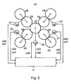
- Fig. 2 is a 9-cylinder satellite pressure unit 14 with four possible pressure points 01 shown, where the paper web 02 is printable in the print-on position. (Pressure points 01 and paper web 02 and elevators 09 are in Fig. 2 and 3 not explicitly shown).
- Fig. 1 are now four transfer cylinder 04 selectively adjustable to a running as a satellite cylinder 03 impression cylinder 03.
- the transfer cylinder 04 and the cooperating forme cylinder 08 are each driven in pairs together by means of the drive motor 07.
- Fig. 1 are between the drive motors 06; 07 and the controller 11 no drive controls 12; 13 is shown.
- the type of elevators 09 positive, negative, neutral promotional
- the conveying behavior of the paper type used for the paper web 02 can be at constant peripheral speed u03 or speed n06 controlled satellite cylinder 03, the regenerative or Motor power L06 on the drive motor 06 again significantly fluctuate.
- the drive motors 07 of the present in pressure-on-position transfer cylinder 04 are controlled by the power supply by means of the actual value of the speed n07 as a reference variable to a speed n07-soll, which z. B. the selected production speed u p or the peripheral speed u04-soll on the Transfer cylinders 04 corresponds.
- the supply of power L06 is no longer in terms of a peripheral speed u04 corresponding speed n06-soll or peripheral speed u03-soll, but in the reverse manner by means of the power L06 as a reference variable speed n06 or peripheral speed u03 is regulated with respect to a minimum motor or generator power L06 of the drive motor 06.
- the setpoint u03-soll on the satellite cylinder 03 is z. B. changed by a relative deviation ⁇ u.
- the deviation ⁇ u of the peripheral velocity u03 of the satellite cylinder 03 from the peripheral velocity u04 and the production velocity u p is a lower limit ⁇ u1 (lag) and an upper limit ⁇ u2 (lead), e.g. B. ⁇ 0.02% of the production speed u p , may not fall below or exceed.
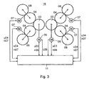
- the two satellite cylinders 03 of a 10-cylinder satellite pressure unit 16 are driven by means of their own drive motor 06, so the regulation with respect to the minimum of the power L06 of each drive motor 06 can take place.
- the control is especially for larger printing units or printing units associations, z. B. for two stacked 9-cylinder satellite pressure units 14 or for stacked 10-cylinder satellite pressure units 16 applicable.
- the paper web 02 is on both sides four-color, or z. B. each two-sided two-color with full Imprinterfunktion gleich printable.
- the regulation of a drive motors 06; 07 of the cylinder 03; 04 by means of the power L06 as a reference variable is not limited to the counter-pressure or satellite cylinder 03 shown in the examples. It can also be reversed during the production of the satellite cylinder 03 by means of the actual value of the speed n06 or the peripheral speed u03 as a reference variable to a constant Speed n06-soll or a constant peripheral speed u03-soll is to be regulated, while the one or more co-operating transfer cylinder 04 is controlled by means of a power, not shown, as a reference variable to a minimum power in the relevant interval.
- the described control avoids, in particular, a high regenerative power L06, without the quality of the product being outside a tolerable range. This is different for use promotional blankets 09.
- an adjustment of the different peripheral speed u03; u04 via an adjustable gear G is designed as an electronic gear G.
- the electronic gear G represents a means which is suitable or effective, the rotational speed (and / or rotational angular position) of the drive motor 06; 07 individually in relation to a predetermined main standard, e.g. B. a virtual master axis 17 to control.
- This electronic gear G is preferably in a respective drive motor 06; 07 associated drive control 12; 13 integrated and allows the speed (and / or rotational position) of the drive motor 06; 07 to change a preselected factor compared to the main standard.
- This is preferably done electronically, e.g. by means of an implemented algorithm which controls the drive of the relevant cylinder 03; 04 can run faster or slower according to the factor than specified by the main standard (leading axis 17).
- the desired angular position (and / or the speed corresponding to the engine speed) for the drive motors 06; 07 is z. B. from the virtual master axis 17 via a network the drive motors 06; 07 given. About this network, or advantageous over another, not shown, signal connection, z. B. a second network, the transmission G of the preselected or determined by the control factor (or comparable information) is transmitted.
- the relevant cylinder 03; 04 rotates as a result with a deviating from the specification on the leading axis 17 speed or peripheral speed when the factor is not equal to 1. For example, rotates the impression cylinder 03 with a factor of up to ⁇ 100.2%, in automatic operation z. B. up to ⁇ 100.02%, different from the transfer cylinder 04th
- At least one of the drive motors 06; 07 of the two together on the web 02 acting cylinder 03; 04 has in its drive control 12; 13 such a transmission G on.
- This gear G is now adjustable either via a control station or directly on site in its translation.
- the two peripheral speeds u03; 04 according to the invention are now changed over the setting of the or the transmission G so that they are different from each other, d. H. a relative deviation ⁇ u in their geometrically resulting peripheral velocities u03; u04 received.
- the relative deviation .DELTA.u to be set can be different for different elevator types / types (manufacturer and / or class, etc.), substrates, for different printing methods and / or different quality requirements, different productions and / or different web guides.
- the described arrangement and design of the transmission G is to be applied advantageously both for the control described above to minimum power to the controller based stored, predetermined deviations ⁇ u, as well as the below-described control threshold.
- a setting for the desired deviation ⁇ u (or the translation of the corresponding gear G) can be determined.
- This can, for. B. in the form of gear ratios Ü1; Ü2 of the transmission G, for said one or more of the above conditions in a storage unit, in the control room or otherwise suitable Way be filed.
- Corresponding translations can, however, by the operator, for example, directly, for. B. at the control room, be specified or changed.
- T. set out in response to a measured power L06 (torque) on the drive motor 06 of the impression cylinder 03, a measured power L07 (torque) of one or more drive motors 07 on the pair or on pairs or in combination. It is essential that, in particular in automatic control, the change in the relative peripheral speed (speed) of the participating cylinder 03; 04 as a function of a determined power L06; L07 (or moment) takes place.
- the described arrangements thus make it possible to reduce the moment between the drive motors 06; 07, in particular between the drive motor 07 (or the drive motors 07) of the printing unit (form and transfer cylinder 08, 04) and the drive motor 06 of the impression cylinder 03 compensate.
- This can be a possible overload on a drive motor 06; 07, the production need not be interrupted.
- the control acts as described in an advantageous embodiment on the speed of one of the cylinder 03; 04; 08 or its drive motor 06; 07, in particular to that of the impression cylinder 03.
- the scheme is switched on and switched off and has z. B. via a manual and / or automatic mode.
- the control In an "off" mode, the control is inactive, it does not make any intervention. The regulation then exerts no influence on the drives or on the printing process.
- the manual mode allows, as described above, a self-selected lead or lag (translation).
- This mode can be used, for example, if either no automatic is provided, it is unsuitable for the current operating conditions, or there is a fault in the automatic.
- the permitted range for setting a lead or lag is z. B. up to ⁇ 0.2%.
- the overfeed is selected so that the drive motors 06; 07 of the impression cylinder 03 and / or the drive motor 07 (or the drive motors 07) of the printing unit (forming and transfer cylinders 08, 04) do not go into overload.
- the control intervenes, for example, as soon as a drive motor 06; 07 a threshold or limit of z. Over ⁇ 90%, in safe execution ⁇ 80% of a rated torque (or power L06; L07). If the threshold or limit value is exceeded, then the regulation causes a change in the relative peripheral speeds u03; u04 to each other, z. B.
- the regulation preferably has a delay element or is otherwise strongly attenuated in such a way that short-term changes do not lead to constant fluctuations in the circumferential velocities u03; u04 lead and / or vibrations of the control are caused.
- the control operates in such a way that a resulting moment (or power L06, L07) is set at approximately 75 to 100%, in particular 90 to 100%, torque of the endangered drive.
- a resulting moment or power L06, L07
- the control is strongly damped, so that short fluctuations at the moment do not affect the overfeed.
- the permitted range for the adjustment of a lead or lag in the automatic method is advantageously up to ⁇ 0.02%, in particular up to ⁇ 0.015%.
Landscapes
- Engineering & Computer Science (AREA)
- Mechanical Engineering (AREA)
- Inking, Control Or Cleaning Of Printing Machines (AREA)
- Rotary Presses (AREA)
Abstract
Claims (16)
- Procédé d'entraînement d'une unité d'impression, avec au moins un cylindre de contre-pression (03) et un cylindre (04) formant avec celui-ci un emplacement d'impression (01), les deux cylindres (03 ; 04), coopérant et se trouvant en contact de pression, pouvant pendant la production être entraînés avec des vitesses périphériques (u03 ; u04) différentes l'une de l'autre à l'emplacement d'emprise, caractérisé en ce qu'un réglage des différentes vitesses périphériques (u03 ; u04), pendant la production, s'effectue par l'intermédiaire d'au moins une transmission électronique (G) à rapport de transmission variable, associée à un moteur d'entraînement (06 ; 07) d'un des deux cylindres (03 ; 04).
- Procédé selon la revendication 1, caractérisé en ce que le réglage du rapport de transmission s'effectue à la transmission électronique (G) d'un moteur d'entraînement (06 ; 07) au reste régulé quant à sa position angulaire en rotation.
- Procédé selon la revendication 2, caractérisé en ce que, au moyen de la transmission électronique (G), une vitesse de rotation et/ou une position angulaire en rotation du moteur d'entraînement (06 ; 07) est/sont modifiée(s) de la valeur d'un facteur susceptible d'être présélectionné, par rapport à un standard principal situé en une relation fixe avec la vitesse machine.
- Procédé selon la revendication 3, caractérisé en ce qu'un facteur présélectionné est affecté à la commande (12 ; 13) du moteur d'entraînement (06 ; 07), pour modifier une position angulaire en rotation et/ou une vitesse de rotation, corrélée(s) avec la vitesse machine, pour les moteurs d'entraînement (06 ; 07), attribuée(s) par l'axe directeur virtuel (17) et la transmission (G).
- Procédé selon la revendication 1, caractérisé en ce qu'un réglage des vitesses périphériques (u03 ; u04) entre elles est modifié, dès que, à la position d'application de pression, une valeur limite d'une puissance (L06 ; L07) consommée, ou d'un couple appliqué, du moteur d'entraînement (06 ; 07) entraînant le cylindre de contre-pression (03) et/ou le cylindre (04), est dépassée.
- Procédé selon la revendication 5, caractérisé en ce qu'aucune modification n'est effectuée, tant que la puissance (L06 ; L07), ou le couple appliqué, est inférieur(e) à la valeur limite.
- Procédé selon la revendication 1, caractérisé en ce que le réglage des vitesses périphériques (u03 ; u04) entre elles s'effectue au moyen d'une régulation.
- Procédé selon la revendication 1, caractérisé en ce que le réglage des vitesses périphériques (u03 ; u04) entre elles s'effectue au moyen d'une commande.
- Procédé selon la revendication 7 ou 8, caractérisé en ce que le réglage, ou la commande, agit sur la vitesse de rotation du cylindre de contre-pression (03).
- Procédé selon la revendication 1, caractérisé en ce que le procédé est mis en oeuvre manuellement.
- Procédé selon la revendication 1, caractérisé en ce que le procédé est mis en oeuvre automatiquement.
- Procédé selon la revendication 1, caractérisé en ce qu'un écart (Au) des deux vitesses (u03 ; u04) entre elles est réglé en fonction d'au moins une sorte et/ou une caractérisation de blanchet.
- Procédé selon la revendication 5, caractérisé en ce qu'est utilisée comme valeur limite une valeur dans la fourchette comprise entre 70 et 90 % d'un couple nominal du moteur d'entraînement (06 ;07).
- Procédé selon la revendication 1, caractérisé en ce qu'une valeur limite pour une différence maximale des vitesses périphériques (u03 ; u04) est respectée.
- Procédé selon les revendications 10 et 14, caractérisé en ce que la valeur limite pour la différence des vitesses périphériques (u03 ; u04) en fonctionnement manuel est au maximum de ± 0,2 %.
- Procédé selon les revendications 11 et 14, caractérisé en ce que la valeur limite pour la différence des vitesses périphériques (u03 ; u04) en fonctionnement automatique est au maximum de ± 0,02 %.
Applications Claiming Priority (7)
| Application Number | Priority Date | Filing Date | Title |
|---|---|---|---|
| WOPCT/DE02/00805 | 2002-03-06 | ||
| PCT/DE2002/000805 WO2002074540A1 (fr) | 2001-03-20 | 2002-03-06 | Procedes et dispositifs pour entrainer une unite d'impression |
| DE10244934 | 2002-09-25 | ||
| DE10244934 | 2002-09-25 | ||
| DE10252796 | 2002-11-13 | ||
| DE10252796 | 2002-11-13 | ||
| PCT/DE2003/000670 WO2003074275A1 (fr) | 2002-03-06 | 2003-02-28 | Procede d'entrainement d'une unite d'impression |
Publications (2)
| Publication Number | Publication Date |
|---|---|
| EP1494860A1 EP1494860A1 (fr) | 2005-01-12 |
| EP1494860B1 true EP1494860B1 (fr) | 2012-03-14 |
Family
ID=27791821
Family Applications (1)
| Application Number | Title | Priority Date | Filing Date |
|---|---|---|---|
| EP03722204A Expired - Lifetime EP1494860B1 (fr) | 2002-03-06 | 2003-02-28 | Procede d'entrainement d'une unite d'impression |
Country Status (3)
| Country | Link |
|---|---|
| EP (1) | EP1494860B1 (fr) |
| AU (1) | AU2003229485A1 (fr) |
| WO (1) | WO2003074275A1 (fr) |
Families Citing this family (1)
| Publication number | Priority date | Publication date | Assignee | Title |
|---|---|---|---|---|
| FR2948061B1 (fr) * | 2009-07-15 | 2011-09-02 | Goss Int Montataire Sa | Procede de reglage de la vitesse angulaire de cylindres d'impression |
Family Cites Families (3)
| Publication number | Priority date | Publication date | Assignee | Title |
|---|---|---|---|---|
| DE19501243C5 (de) | 1995-01-17 | 2004-01-29 | Maschinenfabrik Wifag | Schmitzringlagerung für einen Zylinder einer Rotationsdruckmaschine |
| DE19527199C2 (de) | 1995-07-26 | 2002-10-31 | Baumueller Nuernberg Gmbh | Flexodruckmaschine und deren Verwendung |
| WO2000041887A1 (fr) | 1999-01-18 | 2000-07-20 | Koenig & Bauer Aktiengesellschaft | Dispositif d'entrainement de cylindres |
-
2003
- 2003-02-28 EP EP03722204A patent/EP1494860B1/fr not_active Expired - Lifetime
- 2003-02-28 WO PCT/DE2003/000670 patent/WO2003074275A1/fr not_active Application Discontinuation
- 2003-02-28 AU AU2003229485A patent/AU2003229485A1/en not_active Abandoned
Also Published As
| Publication number | Publication date |
|---|---|
| AU2003229485A1 (en) | 2003-09-16 |
| EP1494860A1 (fr) | 2005-01-12 |
| WO2003074275A1 (fr) | 2003-09-12 |
Similar Documents
| Publication | Publication Date | Title |
|---|---|---|
| DE4430693B4 (de) | Antriebe für eine Rollenrotations-Offsetdruckmaschine | |
| EP1155826B1 (fr) | Machine rotative d'impression | |
| EP0081186B1 (fr) | Procédé et dispositif pour diminuer les fautes de repérage dans des machines à imprimer rotatives à plusieurs couleurs | |
| EP0812682B1 (fr) | Entraínement pour une machine à imprimer | |
| DE9321320U1 (de) | Rotationsdruckmaschine mit paarweise zu Zylindergruppen zusammengefaßten Gummituch und Platten- bzw. Formzylindern | |
| DE19501243C2 (de) | Schmitzringlagerung für einen Zylinder einer Rotationsdruckmaschine | |
| EP1040917A1 (fr) | Procédé et dispositif à compensation de vibrations torsionelles d'une machine à imprimer | |
| DE19941235A1 (de) | Druckwerk einer Rollenrotations-Druckmaschine | |
| DE19521827A1 (de) | Druckmaschinen-Direktantrieb | |
| WO2003013856A1 (fr) | Procédé pour mettre en prise et arrêter des cylindres | |
| DE69400403T2 (de) | Verfahren und Vorrichtung zum Nacheinander Bedrucken von Bogen | |
| EP1447218A2 (fr) | Dispositif d'entraínement de cylindres d'une machine d'impression rotative | |
| DE10113338B4 (de) | Verfahren und Vorrichtungen zum Antrieb einer Druckeinheit | |
| EP1494860B1 (fr) | Procede d'entrainement d'une unite d'impression | |
| EP1464488B1 (fr) | Imprimante | |
| DE4344912C2 (de) | Antrieb eines farbübertragenden Druckzylinders einer Rollenrotationsdruckmaschine | |
| EP1871603B1 (fr) | Systemes d'encrage d'une presse d'imprimerie et procede permettant de faire fonctionner un systeme d'encrage | |
| EP0692377B2 (fr) | Procédé et dispositif pour l'entraînement synchrone de composants d'une machine d'impression | |
| EP2233291B1 (fr) | Groupe d'impression et procédé pour l'opérer | |
| EP1110722B1 (fr) | Presse d'impression offset | |
| DE2324684A1 (de) | Farb- und feuchtwerksantrieb fuer rotationsdruckmaschinen | |
| EP1523409A1 (fr) | Procede et dispositif pour reduire les vibrations au niveaux d'elements rotatifs et element rotatif correspondant amorti en vibrations | |
| DE29513635U1 (de) | Rotationsdruckmaschine mit Zylindern, die zu motorisch einzeln angetriebenen Zylindergruppen zusammengefaßt sind | |
| DE102007020225A1 (de) | Vorrichtung zur Synchronisierung der Drehbewegung von einzeln angetriebenen Rotationskörpern | |
| DE9421938U1 (de) | Rotationsdruckmaschine mit paarweise zu Zylindergruppen zusammengefaßten Gummituch- und Platten- bzw. Formzylindern |
Legal Events
| Date | Code | Title | Description |
|---|---|---|---|
| PUAI | Public reference made under article 153(3) epc to a published international application that has entered the european phase |
Free format text: ORIGINAL CODE: 0009012 |
|
| 17P | Request for examination filed |
Effective date: 20040331 |
|
| AK | Designated contracting states |
Kind code of ref document: A1 Designated state(s): AT BE BG CH CY CZ DE DK EE ES FI FR GB GR HU IE IT LI LU MC NL PT SE SI SK TR |
|
| AX | Request for extension of the european patent |
Extension state: AL LT LV MK RO |
|
| 17Q | First examination report despatched |
Effective date: 20080929 |
|
| GRAP | Despatch of communication of intention to grant a patent |
Free format text: ORIGINAL CODE: EPIDOSNIGR1 |
|
| GRAS | Grant fee paid |
Free format text: ORIGINAL CODE: EPIDOSNIGR3 |
|
| GRAA | (expected) grant |
Free format text: ORIGINAL CODE: 0009210 |
|
| AK | Designated contracting states |
Kind code of ref document: B1 Designated state(s): AT BE BG CH CY CZ DE DK EE ES FI FR GB GR HU IE IT LI LU MC NL PT SE SI SK TR |
|
| REG | Reference to a national code |
Ref country code: GB Ref legal event code: FG4D Free format text: NOT ENGLISH |
|
| REG | Reference to a national code |
Ref country code: CH Ref legal event code: EP Ref country code: AT Ref legal event code: REF Ref document number: 549162 Country of ref document: AT Kind code of ref document: T Effective date: 20120315 |
|
| REG | Reference to a national code |
Ref country code: IE Ref legal event code: FG4D Free format text: LANGUAGE OF EP DOCUMENT: GERMAN |
|
| REG | Reference to a national code |
Ref country code: DE Ref legal event code: R096 Ref document number: 50314265 Country of ref document: DE Effective date: 20120510 |
|
| REG | Reference to a national code |
Ref country code: NL Ref legal event code: VDEP Effective date: 20120314 |
|
| PG25 | Lapsed in a contracting state [announced via postgrant information from national office to epo] |
Ref country code: GR Free format text: LAPSE BECAUSE OF FAILURE TO SUBMIT A TRANSLATION OF THE DESCRIPTION OR TO PAY THE FEE WITHIN THE PRESCRIBED TIME-LIMIT Effective date: 20120615 Ref country code: FI Free format text: LAPSE BECAUSE OF FAILURE TO SUBMIT A TRANSLATION OF THE DESCRIPTION OR TO PAY THE FEE WITHIN THE PRESCRIBED TIME-LIMIT Effective date: 20120314 |
|
| PG25 | Lapsed in a contracting state [announced via postgrant information from national office to epo] |
Ref country code: CY Free format text: LAPSE BECAUSE OF FAILURE TO SUBMIT A TRANSLATION OF THE DESCRIPTION OR TO PAY THE FEE WITHIN THE PRESCRIBED TIME-LIMIT Effective date: 20120314 |
|
| PG25 | Lapsed in a contracting state [announced via postgrant information from national office to epo] |
Ref country code: EE Free format text: LAPSE BECAUSE OF FAILURE TO SUBMIT A TRANSLATION OF THE DESCRIPTION OR TO PAY THE FEE WITHIN THE PRESCRIBED TIME-LIMIT Effective date: 20120314 Ref country code: SE Free format text: LAPSE BECAUSE OF FAILURE TO SUBMIT A TRANSLATION OF THE DESCRIPTION OR TO PAY THE FEE WITHIN THE PRESCRIBED TIME-LIMIT Effective date: 20120314 Ref country code: SI Free format text: LAPSE BECAUSE OF FAILURE TO SUBMIT A TRANSLATION OF THE DESCRIPTION OR TO PAY THE FEE WITHIN THE PRESCRIBED TIME-LIMIT Effective date: 20120314 Ref country code: CZ Free format text: LAPSE BECAUSE OF FAILURE TO SUBMIT A TRANSLATION OF THE DESCRIPTION OR TO PAY THE FEE WITHIN THE PRESCRIBED TIME-LIMIT Effective date: 20120314 |
|
| PG25 | Lapsed in a contracting state [announced via postgrant information from national office to epo] |
Ref country code: SK Free format text: LAPSE BECAUSE OF FAILURE TO SUBMIT A TRANSLATION OF THE DESCRIPTION OR TO PAY THE FEE WITHIN THE PRESCRIBED TIME-LIMIT Effective date: 20120314 Ref country code: PT Free format text: LAPSE BECAUSE OF FAILURE TO SUBMIT A TRANSLATION OF THE DESCRIPTION OR TO PAY THE FEE WITHIN THE PRESCRIBED TIME-LIMIT Effective date: 20120716 |
|
| PLBE | No opposition filed within time limit |
Free format text: ORIGINAL CODE: 0009261 |
|
| STAA | Information on the status of an ep patent application or granted ep patent |
Free format text: STATUS: NO OPPOSITION FILED WITHIN TIME LIMIT |
|
| PG25 | Lapsed in a contracting state [announced via postgrant information from national office to epo] |
Ref country code: NL Free format text: LAPSE BECAUSE OF FAILURE TO SUBMIT A TRANSLATION OF THE DESCRIPTION OR TO PAY THE FEE WITHIN THE PRESCRIBED TIME-LIMIT Effective date: 20120314 Ref country code: DK Free format text: LAPSE BECAUSE OF FAILURE TO SUBMIT A TRANSLATION OF THE DESCRIPTION OR TO PAY THE FEE WITHIN THE PRESCRIBED TIME-LIMIT Effective date: 20120314 |
|
| 26N | No opposition filed |
Effective date: 20121217 |
|
| PG25 | Lapsed in a contracting state [announced via postgrant information from national office to epo] |
Ref country code: IT Free format text: LAPSE BECAUSE OF FAILURE TO SUBMIT A TRANSLATION OF THE DESCRIPTION OR TO PAY THE FEE WITHIN THE PRESCRIBED TIME-LIMIT Effective date: 20120314 |
|
| REG | Reference to a national code |
Ref country code: DE Ref legal event code: R097 Ref document number: 50314265 Country of ref document: DE Effective date: 20121217 |
|
| PG25 | Lapsed in a contracting state [announced via postgrant information from national office to epo] |
Ref country code: ES Free format text: LAPSE BECAUSE OF FAILURE TO SUBMIT A TRANSLATION OF THE DESCRIPTION OR TO PAY THE FEE WITHIN THE PRESCRIBED TIME-LIMIT Effective date: 20120625 |
|
| PG25 | Lapsed in a contracting state [announced via postgrant information from national office to epo] |
Ref country code: BG Free format text: LAPSE BECAUSE OF FAILURE TO SUBMIT A TRANSLATION OF THE DESCRIPTION OR TO PAY THE FEE WITHIN THE PRESCRIBED TIME-LIMIT Effective date: 20120614 |
|
| BERE | Be: lapsed |
Owner name: KOENIG & BAUER A.G. Effective date: 20130228 |
|
| PG25 | Lapsed in a contracting state [announced via postgrant information from national office to epo] |
Ref country code: MC Free format text: LAPSE BECAUSE OF NON-PAYMENT OF DUE FEES Effective date: 20130228 |
|
| REG | Reference to a national code |
Ref country code: CH Ref legal event code: PL |
|
| GBPC | Gb: european patent ceased through non-payment of renewal fee |
Effective date: 20130228 |
|
| PG25 | Lapsed in a contracting state [announced via postgrant information from national office to epo] |
Ref country code: LI Free format text: LAPSE BECAUSE OF NON-PAYMENT OF DUE FEES Effective date: 20130228 Ref country code: CH Free format text: LAPSE BECAUSE OF NON-PAYMENT OF DUE FEES Effective date: 20130228 |
|
| REG | Reference to a national code |
Ref country code: FR Ref legal event code: ST Effective date: 20131031 |
|
| REG | Reference to a national code |
Ref country code: IE Ref legal event code: MM4A |
|
| REG | Reference to a national code |
Ref country code: DE Ref legal event code: R119 Ref document number: 50314265 Country of ref document: DE Effective date: 20130903 |
|
| PG25 | Lapsed in a contracting state [announced via postgrant information from national office to epo] |
Ref country code: BE Free format text: LAPSE BECAUSE OF NON-PAYMENT OF DUE FEES Effective date: 20130228 Ref country code: DE Free format text: LAPSE BECAUSE OF NON-PAYMENT OF DUE FEES Effective date: 20130903 Ref country code: FR Free format text: LAPSE BECAUSE OF NON-PAYMENT OF DUE FEES Effective date: 20130228 Ref country code: GB Free format text: LAPSE BECAUSE OF NON-PAYMENT OF DUE FEES Effective date: 20130228 Ref country code: IE Free format text: LAPSE BECAUSE OF NON-PAYMENT OF DUE FEES Effective date: 20130228 |
|
| REG | Reference to a national code |
Ref country code: AT Ref legal event code: MM01 Ref document number: 549162 Country of ref document: AT Kind code of ref document: T Effective date: 20130228 |
|
| PG25 | Lapsed in a contracting state [announced via postgrant information from national office to epo] |
Ref country code: AT Free format text: LAPSE BECAUSE OF NON-PAYMENT OF DUE FEES Effective date: 20130228 |
|
| PG25 | Lapsed in a contracting state [announced via postgrant information from national office to epo] |
Ref country code: TR Free format text: LAPSE BECAUSE OF FAILURE TO SUBMIT A TRANSLATION OF THE DESCRIPTION OR TO PAY THE FEE WITHIN THE PRESCRIBED TIME-LIMIT Effective date: 20120314 |
|
| PG25 | Lapsed in a contracting state [announced via postgrant information from national office to epo] |
Ref country code: HU Free format text: LAPSE BECAUSE OF FAILURE TO SUBMIT A TRANSLATION OF THE DESCRIPTION OR TO PAY THE FEE WITHIN THE PRESCRIBED TIME-LIMIT; INVALID AB INITIO Effective date: 20030228 Ref country code: LU Free format text: LAPSE BECAUSE OF NON-PAYMENT OF DUE FEES Effective date: 20130228 |