EP1523224B2 - Cartouche chauffante électrique - Google Patents
Cartouche chauffante électrique Download PDFInfo
- Publication number
- EP1523224B2 EP1523224B2 EP03020876A EP03020876A EP1523224B2 EP 1523224 B2 EP1523224 B2 EP 1523224B2 EP 03020876 A EP03020876 A EP 03020876A EP 03020876 A EP03020876 A EP 03020876A EP 1523224 B2 EP1523224 B2 EP 1523224B2
- Authority
- EP
- European Patent Office
- Prior art keywords
- housing body
- heating cartridge
- electrical heating
- bodies
- designed
- Prior art date
- Legal status (The legal status is an assumption and is not a legal conclusion. Google has not performed a legal analysis and makes no representation as to the accuracy of the status listed.)
- Expired - Lifetime
Links
Images
Classifications
-
- H—ELECTRICITY
- H05—ELECTRIC TECHNIQUES NOT OTHERWISE PROVIDED FOR
- H05B—ELECTRIC HEATING; ELECTRIC LIGHT SOURCES NOT OTHERWISE PROVIDED FOR; CIRCUIT ARRANGEMENTS FOR ELECTRIC LIGHT SOURCES, IN GENERAL
- H05B3/00—Ohmic-resistance heating
- H05B3/40—Heating elements having the shape of rods or tubes
- H05B3/42—Heating elements having the shape of rods or tubes non-flexible
- H05B3/44—Heating elements having the shape of rods or tubes non-flexible heating conductor arranged within rods or tubes of insulating material
-
- H—ELECTRICITY
- H05—ELECTRIC TECHNIQUES NOT OTHERWISE PROVIDED FOR
- H05B—ELECTRIC HEATING; ELECTRIC LIGHT SOURCES NOT OTHERWISE PROVIDED FOR; CIRCUIT ARRANGEMENTS FOR ELECTRIC LIGHT SOURCES, IN GENERAL
- H05B3/00—Ohmic-resistance heating
- H05B3/40—Heating elements having the shape of rods or tubes
- H05B3/42—Heating elements having the shape of rods or tubes non-flexible
- H05B3/48—Heating elements having the shape of rods or tubes non-flexible heating conductor embedded in insulating material
-
- H—ELECTRICITY
- H05—ELECTRIC TECHNIQUES NOT OTHERWISE PROVIDED FOR
- H05B—ELECTRIC HEATING; ELECTRIC LIGHT SOURCES NOT OTHERWISE PROVIDED FOR; CIRCUIT ARRANGEMENTS FOR ELECTRIC LIGHT SOURCES, IN GENERAL
- H05B2203/00—Aspects relating to Ohmic resistive heating covered by group H05B3/00
- H05B2203/02—Heaters using heating elements having a positive temperature coefficient
Definitions
- the invention relates to an electric heating cartridge according to the preamble of claim 1.
- Cartridges of this type are characterized by their small construction and the fact that they are both heating and temperature control simultaneously.
- This dual function is achieved through the use of PTC elements (Positive Temperature Coefficient), so-called PTC thermistors.
- PTC element has the property of heating only up to a predetermined limit temperature. From this limit temperature, the electrical resistance increases suddenly, so that the PTC element stops heating. As a result, PTC elements are self-regulating and require no additional temperature control. It is possible to produce PTC elements for different electrical voltages and different limit temperatures.
- a structurally simple construction which essentially comprises the actual PTC element and two electrode body, and a simple power supply via a two-wire cable is to realize the relatively small construction of the heating cartridges.
- heating cartridges of the type mentioned have a variety of applications, such as e.g. in industry, medical technology or in the household. They are used, for example, in laminators, inhalers and in the automotive industry.
- a heating cartridge of the prior art is for example in the DE 202 12 580 U1 described.
- the heating cartridge of DE 202 12 580 U1 the power is supplied via the housing body of the heating cartridge. For this reason, the heating cartridge is not suitable for use in electrically conductive or electrically dissociating media.
- Another heating cartridge is in the DE 197 37 241 C2 described.
- two PTC elements with two electrode bodies, which are embedded together in a plurality of insulating elements, received in a metal housing body biased.
- the insulating elements are in this case made of an elastic metal oxide, which are pre-pressed and bias the components within the housing body.
- a disadvantage of the heating cartridge of DE 197 37 241 C2 is that the metal oxide expands depending on temperature, so that different biasing forces are generated depending on the temperature. As a result, the heat energy released by the immersion heater to the medium to be heated varies at different temperatures.
- heating elements are in the DE 201 21 116 U1 and the US 4,822,980 described.
- DE 201 21 116 U1 are several PTC elements with electrode bodies in a housing, which dips in operation in a liquid to be heated, arranged.
- the US 4,822,980 describes a heating element in which a surrounded by an insulating PTC element is disposed in an aluminum housing.
- the aluminum housing is designed with radially acting spring elements and pressed in a pot.
- An electric immersion heater is described, are arranged in the lying between two electrode bodies PTC elements in an elastic insulating tube.
- the Isotierschlauch is in turn surrounded by a longitudinally slotted, radially resilient metal shell.
- the GB 2 079 570 A An electric immersion heater is described in which a PTC element is arranged between two electrode bodies.
- a Kuntstofffolie isolated the electrode body relative to the substantially cup-shaped housing body.
- Two heat-conducting pressure bodies are arranged between the electrically insulating plastic film and the housing body in order to hold the PTC element centered in the housing body.
- the invention has for its object to provide an improved heating cartridge, which is used in liquid or gaseous media and protected from contamination.
- the bias applied by the housing body compresses the components within the housing body. This ensures that the heat conduction surfaces of the housing body and the inner components abut each other and thereby a previously calculated heat energy to be delivered is transferable to the medium to be heated. Because, in contrast to the prior art, the housing body now serves as a spring element, a uniform preload force can be generated over wide temperature ranges. Surprisingly, the temperature dependence of the biasing force generated by the housing body seems to be less pronounced than in the embodiment of the insulating body as spring elements. One reason for this could be the small wall thickness of the housing body. This ensures a secure concern the perennial leit perennial fever of the components together.
- the bias voltage is well passed to the electrode body and the PTC element.
- the thus improved heating device can be further developed by various independent and each advantageous developments, as they are explained below.
- the housing body made of an elastic material be designed. This has the advantage that the housing body is elastically deformable and thereby the bias can be generated in the interior of the housing body.
- the housing body can be made substantially pot-shaped.
- the heating cartridge according to the invention must be closed only on one side, thereby reducing the cost of mounting the heating element and the number of items.
- the substantially cup-shaped housing body may also be made of a thin-walled material, e.g. by deep drawing.
- the housing body is elastic and on the other hand, he can thereby better direct the generated heat energy to the outside.
- the shape of the pot-shaped housing body is not limited and may e.g. be cylindrical, but also four, six or octagonal executed.
- the housing body can, in an advantageous development, be made of a corrosion-resistant material, e.g. a metal, be made.
- the housing body may also be made of an acid-resistant material.
- the at least one insulating element is made of a plastic film.
- the plastic film may be a polyimide film. This material is particularly suitable because it provides good electrical insulation and on the other is particularly thermally conductive.
- the polyimide film may be, for example, a Kapton film. The design as a thin-walled film in this case enhances the inelasticity of the insulating element, so that the spring force is generated almost exclusively by the housing body.
- the electrode body can each have a contact element, by which the electrode body can be connected to a voltage source.
- the contact elements may be designed as a welding contact or as a plug to provide a good connection option.
- the electrode bodies are also usually made of a thermally conductive material, in particular a metal.
- the heating cartridge according to the invention may comprise at least two heat-conducting pressure bodies, which are formed by a spring force transferring from the housing body in the direction of at least one PTC element.
- the pressure bodies are made of a low cost, easy to produce thermally conductive material, e.g. made of extruded aluminum, can be made and so fill the housing body, transfer heat and conduct the spring force inward.
- the cost-effective components, such as PTC element, electrode body and insulating element can thereby be made smaller and thus save material, which leads to the reduction of material costs.
- the pressure bodies can in particular be arranged between the housing body and the PTC element. You can also sandwich the PTC element.
- the pressure bodies can be designed as electrode body. You may also be surrounded by the insulating in a development.
- the width of a stack of the pressure bodies, the at least one insulating element, the electrode bodies and the at least one PTC element in an advantageous development can be greater than the inside diameter of the housing body.
- the housing body is elastically expanded when the stack is inserted into the housing body. This elastic expansion creates the desired preload inside the heating cartridge.
- the magnitude of the bias voltage can be predetermined.
- the elasticity of the pressure body is dimensioned smaller than that of the housing body. Due to the higher elasticity, the pressure bodies remain under the action of the biasing force therefore substantially undeformed.
- the heating cartridge may have at least one closure element, by which the housing body is substantially closed fluid-tight.
- closure element may be made in a further advantageous embodiment of a permanently elastic material, in particular an elastomer. This is advantageous because permanently elastic material is resistant to aging and does not break or become porous even with temperature fluctuations.
- the closure element can be designed to be resistant to corrosion and / or acid.
- the housing body may be configured with a latching means into which the closure element engages positively with a corresponding mating catch.
- the closure element is fixed in a simple manner in the housing body.
- the locking means of the housing body for example, in a tubular receiving device be attached.
- the closure element can be configured in an advantageous development with a holding means which is formed axially securing the pressure body.
- the heating cartridge may comprise at least one connection element, by which the electrode body can be connected to a voltage source.
- the at least one connecting element can also be designed as a fastening element and hold the heating cartridge in the medium to be heated.
- the heating cartridge e.g. when heating a liquid medium directly and without receiving means are mounted in this, held by the connecting element.
- the closure element may have at least one sealed opening through which a respective connection element extends.
- the closure element may be formed as a part of a plug-in connection into which, for example, a plug element for supplying power to the heating cartridge can be inserted.
- the plug connection for the use of the immersion heater in liquids is designed to be fluid-tight.
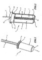
- Fig. 1 shows an embodiment of the electric heating cartridge 1 according to the invention with a housing body 2 and two connection elements 3.
- the housing body 2 is in Fig. 1 by way of example cup-shaped, whereby the heating element 1 is automatically closed at the bottom 4 of the housing body 2.
- the housing body 2 is cylindrical and thus z. B. in a tubular receiving device in a plug E E inserted.
- the heating cartridge 1 can be inserted up to a flange-shaped stopper 5 in the receiving device. Below the stop 5 is located on the housing body 2, a locking means 6 in the form of a hollow bead. By the latching means 6, the heating cartridge 1 is fixed in the receiving device.
- the fixation can be achieved in that the outer diameter of the locking means 6 is greater than the inner diameter of the receiving device, whereby the heating element 1 is frictionally fixed in the receiving device.
- the receiving device has a recess into which the locking means 6 engages positively and thus fixes the heating cartridge 1.
- the locking means 6 is in Fig. 1 exemplified circumferentially on the entire circumference of the housing body 2.
- the latching means 6 is designed, for example, only in sections on the circumference of the housing body 2.
- connection elements 3 e.g. in the form of a plug-in connection, emerge at the top from the housing body 2 for connection of the heating cartridge 1 to a voltage source (not shown).
- connection elements 3 there is also a further possibility of mounting the heating cartridge 1 according to the invention.
- the connection elements 3 are made of a flexibly bendable material.
- the connecting elements 3 serve in this embodiment as fastening elements and the heating cartridge 1 is, hanging on the connecting elements 3, placed directly in the medium to be heated. By manually bending the connection elements 3, the position of the heating cartridge 1 can be varied.
- the housing body 2 is made of a corrosion and acid resistant material, e.g. a metal, made.
- Fig. 2 shows by way of example the embodiment of the heating cartridge 1 according to the invention Fig. 1 in full section 1, whereby the components in the interior of the housing body 2 are visible in the installed state.
- the heating cartridge 1 according to the invention comprises a stack of two pressure bodies 7, an insulating element 8, two electrode bodies 9 and a PTC element 10 in the interior of the housing body 2.
- the PTC element 10 is formed as a thin, preferably rectangular plate with the largest possible Plate surface designed to form a maximum heat conduction surface.
- the PTC element 10 is in a position within the housing body 2, in which it can take the greatest possible length. This position is, for example, a diameter for a housing body with a circular cross section and a diagonal for a body with a polygonal cross section.
- the two Electrode bodies 9 are substantially formed as thin, preferably rectangular plates and have at least the same plate surface as the PTC element 10 so that they can supply the PTG element 10 on the entire plate surface with power and can dissipate the generated heat well.
- the electrode bodies 9 are each connected via a connection element 3 to a voltage source (not shown).
- a connection element 3 to a voltage source (not shown).
- Fig. 2 only one of two connection elements 3 is shown, since the other connection element 3, which connects the second electrode body to the voltage source, is located in the non-illustrated part of the heating cartridge 1.
- the connecting elements 3 and the electrode body 9 may be configured in one piece.
- the insulating 8 isolates the electrode body 9 and the PTC element 10 electrically against the pressure bodies 7 and the housing body 2. But one To ensure good heat conduction from the PTC element 10 and the electrode bodies 9 to the pressure bodies 7, the insulating member 8 is made of a thermally conductive material. In the exemplary embodiment in FIG Fig. 2 the insulating element 8 is made of a polyimide film, in particular of a Kapton film.
- the PTC element 10, the electrode body 9 and the insulating body 8 are sandwiched between the two semicircular pressure bodies 7.
- the pressure bodies 7 are made of a thermally conductive material, e.g. made of aluminum, and are completely on the electrode bodies 9 and on the insulating element 8 at.
- the stack 7, 8, 9, 10 is located in the interior of the housing body 2 and is under a bias, since the width of the stack is greater than the inside diameter of the housing body 2, whereby the wall of the housing body 2 is elastically deflected outwardly and thereby the bias in the interior of the housing body 2 is formed.
- the bias compresses the two pressure body 7 in a direction of action F together.
- the pressure bodies 7 in turn press the insulating element 8, the electrode body 9 and the PTC element 10 together centrally.
- the housing body 2 is closed at the upper end of a closure element 11.
- the closure element 11 seals the housing body 2 in a fluid-tight manner, so that, for example, a fluid to be heated can not get into the interior of the heating cartridge 1.
- the closure element 11 has a widening which, in the installed state, positively engages in the latching means 6 of the housing body 2 and fixes the closure element 11.
- the closure element 11 has a stop flange 12, which rests in the installed state on the stop 5 of the housing body 2.
- the closure element 11 is made of a permanently elastic plastic, namely an elastomer.
- the elastomer also offers the advantage that the closure element is dimensionally stable with respect to temperature fluctuations, does not age and thus does not leak.
- the elastomer can also be cast directly into the housing body 2 and harden therein, whereby an optimal positive connection with the inner surface of the housing body 2 is achieved.
- the closure element 11 has two sealed openings through which the connection elements 3 lead. Alternatively, the closure element 11 may form a part of a fluid-tight plug connection in which a counterpart of the plug connection for supplying power to the heating cartridge can be inserted.
- the connection elements 3 are likewise sealed by the closure element 11.
- the closure element 11 may be made of a corrosion-resistant material for use in corrosive media.
- a holding means 13 is executed on the closure element 11.
- the holding means 13 limits the pressure bodies 7.
- the pressure bodies 7 are thus fixed in their axial position on one side by a shoulder at the end of the housing body 2 and on the other side by the holding means 13 of the closure element 11.
- an air-filled space which forms an insulating layer and a heat loss down, for example when heating a solid, reduced.
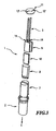
- Fig. 3 shows the electric heating cartridge 1 according to the invention Fig. 1 and 2 in an exploded view.
- the electric heating cartridge 1 comprises the housing body 2 in which the two semicircular pressure bodies 7 are accommodated. Between the two pressure bodies 7 is the PTC element 10, which is surrounded on each side by an electrode body 9, and both are enclosed by the insulating element 8.
- the insulating member 8 in this exemplary illustration is pocket-shaped around the PTC element 10 and the electrode body 9 around. This ensures electrical insulation of the electrode body 9 and the PTC element 10 on five sides.
- PTC element 10 and the electrode body 9 are inserted in the insertion direction E in the pocket-shaped insulating body 8.
- the electrode bodies 9 each comprise a contact element 14 to which the connection element 3 is attached.
- the connection is usually carried out by soldering or welding, but also a pluggable connection is conceivable.
- the heating cartridge 1 is completed by the closure member 11 upwards.
- the individual components are introduced during assembly of the heating element 1 in the insertion direction E in the housing body 2.
Claims (10)
- Cartouche chauffante électrique (1) destinée au chauffage de milieux liquides et/ou gazeux, comportant au moins un élément CTP (10), deux corps d'électrodes (9) associés à l'au moins un élément CTP (10), qui sont montés sous précontrainte de façon comprimée dans un corps de boîtier (2) sensiblement réalisé en forme de pot, électriquement isolé par rapport aux corps d'électrodes (9) par au moins un élément d'isolation (8), le corps de boîtier (2) étant agencé sous la forme d'un élément élastique engendrant la précontrainte, et l'au moins un élément d'isolation (8) réalisé en un film en matière plastique étant agencé de manière non élastique par rapport au corps de boîtier (2), et comportant au moins deux corps de pression (7) conducteurs de chaleur, qui sont formés de façon à transmettre la précontrainte du corps de boîtier (2) en direction de l'au moins un élément CTP (10), caractérisée en ce qu'un espace libre rempli d'air et formant une couche isolante se trouve sur un fond (4) du corps de boîtier (2) entre le corps de boîtier (2) et les corps de pression (7), en ce que la cartouche chauffante (1) comporte au moins un élément de fermeture (11) fabriqué en un matériau à élasticité permanente, avec lequel le corps de boîtier (2) est fermé de façon sensiblement étanche aux fluides et qui est doté d'un moyen de retenue (13) formé de façon à bloquer axialement les corps de pression (7) et comportant au moins un orifice étanche, à travers lequel s'étend un élément de raccordement (3) respectif, en ce que le corps de boîtier (2) est doté de moyens d'encliquetage (6), dans lequel l'élément de fermeture (11) s'encliquette par complémentarité de forme par un crantage antagoniste, et en ce que les corps de pression (7) sont bloqués dans leur position axiale par un épaulement à l'extrémité du corps de boîtier (2) sur un côté, et par le moyen de retenue (13) sur l'autre côté.
- Cartouche électrique chauffante (1) selon la revendication 1, caractérisée en ce que le corps de boîtier (2) est réalisé en un matériau élastique.
- Cartouche électrique chauffante (1) selon la revendication 1 ou 2, caractérisée en ce que le corps de boîtier (2) est sensiblement réalisé en forme de pot.
- Cartouche électrique chauffante (1) selon l'une des revendications précédentes, caractérisée en ce que le corps de boîtier (2) est réalisé en un matériau résistant à la corrosion.
- Cartouche électrique chauffante (1) selon la revendication 4, caractérisée en ce que le film en matière plastique est un film en polyimide.
- Cartouche électrique chauffante (1) selon l'une des revendications précédentes, caractérisée en ce que les corps d'électrodes (9) comportent respectivement un élément de contact (14), par l'intermédiaire duquel les corps d'électrodes (9) peuvent être raccordés à une source de tension.
- Cartouche électrique chauffante (1) selon la revendication 1, caractérisée en ce que la largeur d'une pile constituée des corps de pression (7), de l'au moins un élément d'isolation (8), des corps d'électrodes (9) et de l'au moins un élément CTP (10) est plus importante que la largeur intérieure du corps de boîtier (2).
- Cartouche électrique chauffante (1) selon la revendication 1 ou la revendication 7, caractérisée en ce que les au moins deux corps de pression (7) sont fabriqués en aluminium.
- Cartouche électrique chauffante (1) selon l'une des revendications précédentes, caractérisée en ce que la cartouche chauffante (1) comprend au moins un élément de raccordement (3) qui est construit sous la forme d'un élément de fixation, par l'intermédiaire duquel la cartouche chauffante (1) peut être positionnée dans le milieu à chauffer.
- Cartouche électrique chauffante (1) selon l'une des revendications précédentes, caractérisée en ce que, en ce qui concerne la force de précontrainte, les corps de pression (7) sont agencés de façon moins élastique que le corps de boîtier (2).
Priority Applications (3)
| Application Number | Priority Date | Filing Date | Title |
|---|---|---|---|
| EP03020876A EP1523224B2 (fr) | 2003-09-15 | 2003-09-15 | Cartouche chauffante électrique |
| AT03020876T ATE318065T1 (de) | 2003-09-15 | 2003-09-15 | Elektrische heizpatrone |
| DE50302406T DE50302406D1 (de) | 2003-09-15 | 2003-09-15 | Elektrische Heizpatrone |
Applications Claiming Priority (1)
| Application Number | Priority Date | Filing Date | Title |
|---|---|---|---|
| EP03020876A EP1523224B2 (fr) | 2003-09-15 | 2003-09-15 | Cartouche chauffante électrique |
Publications (3)
| Publication Number | Publication Date |
|---|---|
| EP1523224A1 EP1523224A1 (fr) | 2005-04-13 |
| EP1523224B1 EP1523224B1 (fr) | 2006-02-15 |
| EP1523224B2 true EP1523224B2 (fr) | 2009-11-11 |
Family
ID=34306770
Family Applications (1)
| Application Number | Title | Priority Date | Filing Date |
|---|---|---|---|
| EP03020876A Expired - Lifetime EP1523224B2 (fr) | 2003-09-15 | 2003-09-15 | Cartouche chauffante électrique |
Country Status (3)
| Country | Link |
|---|---|
| EP (1) | EP1523224B2 (fr) |
| AT (1) | ATE318065T1 (fr) |
| DE (1) | DE50302406D1 (fr) |
Cited By (2)
| Publication number | Priority date | Publication date | Assignee | Title |
|---|---|---|---|---|
| DE102010063939A1 (de) | 2010-12-22 | 2012-06-28 | Mahle International Gmbh | Elektrische Heizeinrichtung |
| US20210354530A1 (en) * | 2020-05-15 | 2021-11-18 | Eberspächer Catem Gmbh & Co. Kg | PTC Heating Assembly and Method for Manufacturing the Same |
Families Citing this family (3)
| Publication number | Priority date | Publication date | Assignee | Title |
|---|---|---|---|---|
| DE102010006184A1 (de) | 2010-01-29 | 2011-08-04 | Eichenauer Heizelemente GmbH & Co. KG, 76870 | Elektrische Heizeinrichtung und Verfahren zum Fertigen einer elektrischen Heizeinrichtung |
| WO2019079302A1 (fr) | 2017-10-19 | 2019-04-25 | Tom Richards, Inc. | Ensemble de transfert de chaleur |
| CN111265244A (zh) * | 2018-12-05 | 2020-06-12 | 深圳迈瑞生物医疗电子股份有限公司 | 耦合剂加热装置及超声设备 |
Family Cites Families (7)
| Publication number | Priority date | Publication date | Assignee | Title |
|---|---|---|---|---|
| US2360267A (en) * | 1942-11-23 | 1944-10-10 | Mcgraw Electric Co | Encased heating unit |
| US4822980A (en) * | 1987-05-04 | 1989-04-18 | Gte Products Corporation | PTC heater device |
| DE9200944U1 (fr) * | 1992-01-28 | 1992-03-19 | Tuerk & Hillinger Gmbh, 7200 Tuttlingen, De | |
| JPH07263122A (ja) * | 1994-03-22 | 1995-10-13 | Nichicon Corp | 発熱装置 |
| DE19737241C2 (de) * | 1997-08-27 | 1999-09-30 | Tuerk & Hillinger Gmbh | Elektrischer, mit PTC-Elementen ausgerüsteter, verdichteter Heizkörper |
| DE20121116U1 (de) * | 2001-12-21 | 2003-04-24 | Eichenauer Gmbh & Co Kg F | Elektrische Heizeinrichtung zum Beheizen einer Flüssigkeit in einem Kfz |
| DE20212580U1 (de) * | 2002-08-16 | 2002-10-10 | Tuerk & Hillinger Gmbh | Elektrische Heizpatrone mit PTC-Elementen |
-
2003
- 2003-09-15 AT AT03020876T patent/ATE318065T1/de not_active IP Right Cessation
- 2003-09-15 DE DE50302406T patent/DE50302406D1/de not_active Expired - Lifetime
- 2003-09-15 EP EP03020876A patent/EP1523224B2/fr not_active Expired - Lifetime
Cited By (2)
| Publication number | Priority date | Publication date | Assignee | Title |
|---|---|---|---|---|
| DE102010063939A1 (de) | 2010-12-22 | 2012-06-28 | Mahle International Gmbh | Elektrische Heizeinrichtung |
| US20210354530A1 (en) * | 2020-05-15 | 2021-11-18 | Eberspächer Catem Gmbh & Co. Kg | PTC Heating Assembly and Method for Manufacturing the Same |
Also Published As
| Publication number | Publication date |
|---|---|
| EP1523224B1 (fr) | 2006-02-15 |
| DE50302406D1 (de) | 2006-04-20 |
| EP1523224A1 (fr) | 2005-04-13 |
| ATE318065T1 (de) | 2006-03-15 |
Similar Documents
| Publication | Publication Date | Title |
|---|---|---|
| EP1525426B1 (fr) | Appareil a microstructure destiné a chauffer et pulvériser un fluide | |
| EP2428746B2 (fr) | Echangeur de chaleur | |
| DE2948591C2 (fr) | ||
| DE2804749C3 (de) | Durchlauferhitzer | |
| EP0194507B1 (fr) | Elément chauffant pour chauffer des milieux d'écoulement, en particulier sous forme gazeuse | |
| EP0282085B1 (fr) | Elément de chauffage pour réchauffer des fluides | |
| DE10258257B4 (de) | Elektrische Heizeinrichtung zum Beheizen einer Flüssigkeit in einem Kfz | |
| DE102009058159B4 (de) | Filtereinrichtung für Fluide mit einer elektrischen Heizung und Heizung für eine Filtereinrichtung | |
| EP3273177B1 (fr) | Dispositif de chauffage électrique | |
| DE2551980A1 (de) | Abgedichtete, thermostatische heizvorrichtung | |
| EP1777452A2 (fr) | Connecteur chauffable | |
| EP2355614B1 (fr) | Dispositif de chauffage électrique et procédé de fabrication d'un dispositif de chauffage électrique | |
| EP1523224B2 (fr) | Cartouche chauffante électrique | |
| EP1529470B2 (fr) | Module de chauffage avec surface chauffante et chaudière instantanée et procédé pour sa fabrication | |
| EP1557601B1 (fr) | Clip de chauffage pour une conduite de fluide | |
| DE102012109768A1 (de) | Radiatorelement, Heizstufe und Verfahren zum Herstellen eines Radiatorelementes | |
| DE102021112690A1 (de) | PTC-Heizeinrichtung und Verfahren zu deren Herstellung | |
| WO2011101312A2 (fr) | Système de chauffe | |
| EP0718738A2 (fr) | Elément fonctionnel thermostatique avec un élément chauffant à résistance électrique | |
| EP3424266B1 (fr) | Cartouche de chauffage avec un tube de protection | |
| DE102009054654A1 (de) | Dosiermodul für ein Abgasnachbehandlungssystem eines Kraftfahrzeugs | |
| EP1510688B1 (fr) | Dispositif de chauffage pour un milieu à chauffer | |
| DE102011017387A1 (de) | Thermoelektrisches Modul und Verwendung eines thermoelektrischen Moduls | |
| DE3730195C2 (fr) | ||
| WO2017198245A1 (fr) | Dispositif pour convertir de l'énergie électrique en énergie thermique |
Legal Events
| Date | Code | Title | Description |
|---|---|---|---|
| PUAI | Public reference made under article 153(3) epc to a published international application that has entered the european phase |
Free format text: ORIGINAL CODE: 0009012 |
|
| 17P | Request for examination filed |
Effective date: 20040503 |
|
| AK | Designated contracting states |
Kind code of ref document: A1 Designated state(s): AT BE BG CH CY CZ DE DK EE ES FI FR GB GR HU IE IT LI LU MC NL PT RO SE SI SK TR |
|
| AX | Request for extension of the european patent |
Extension state: AL LT LV MK |
|
| RAP1 | Party data changed (applicant data changed or rights of an application transferred) |
Owner name: DBK DAVID + BAADER GMBH |
|
| GRAP | Despatch of communication of intention to grant a patent |
Free format text: ORIGINAL CODE: EPIDOSNIGR1 |
|
| GRAS | Grant fee paid |
Free format text: ORIGINAL CODE: EPIDOSNIGR3 |
|
| GRAA | (expected) grant |
Free format text: ORIGINAL CODE: 0009210 |
|
| AKX | Designation fees paid |
Designated state(s): AT BE BG CH CY CZ DE DK EE ES FI FR GB GR HU IE IT LI LU MC NL PT RO SE SI SK TR |
|
| AK | Designated contracting states |
Kind code of ref document: B1 Designated state(s): AT BE BG CH CY CZ DE DK EE ES FI FR GB GR HU IE IT LI LU MC NL PT RO SE SI SK TR |
|
| PG25 | Lapsed in a contracting state [announced via postgrant information from national office to epo] |
Ref country code: IT Free format text: LAPSE BECAUSE OF FAILURE TO SUBMIT A TRANSLATION OF THE DESCRIPTION OR TO PAY THE FEE WITHIN THE PRESCRIBED TIME-LIMIT;WARNING: LAPSES OF ITALIAN PATENTS WITH EFFECTIVE DATE BEFORE 2007 MAY HAVE OCCURRED AT ANY TIME BEFORE 2007. THE CORRECT EFFECTIVE DATE MAY BE DIFFERENT FROM THE ONE RECORDED. Effective date: 20060215 Ref country code: RO Free format text: LAPSE BECAUSE OF FAILURE TO SUBMIT A TRANSLATION OF THE DESCRIPTION OR TO PAY THE FEE WITHIN THE PRESCRIBED TIME-LIMIT Effective date: 20060215 Ref country code: IE Free format text: LAPSE BECAUSE OF FAILURE TO SUBMIT A TRANSLATION OF THE DESCRIPTION OR TO PAY THE FEE WITHIN THE PRESCRIBED TIME-LIMIT Effective date: 20060215 Ref country code: SK Free format text: LAPSE BECAUSE OF FAILURE TO SUBMIT A TRANSLATION OF THE DESCRIPTION OR TO PAY THE FEE WITHIN THE PRESCRIBED TIME-LIMIT Effective date: 20060215 Ref country code: SI Free format text: LAPSE BECAUSE OF FAILURE TO SUBMIT A TRANSLATION OF THE DESCRIPTION OR TO PAY THE FEE WITHIN THE PRESCRIBED TIME-LIMIT Effective date: 20060215 Ref country code: NL Free format text: LAPSE BECAUSE OF FAILURE TO SUBMIT A TRANSLATION OF THE DESCRIPTION OR TO PAY THE FEE WITHIN THE PRESCRIBED TIME-LIMIT Effective date: 20060215 Ref country code: GB Free format text: LAPSE BECAUSE OF FAILURE TO SUBMIT A TRANSLATION OF THE DESCRIPTION OR TO PAY THE FEE WITHIN THE PRESCRIBED TIME-LIMIT Effective date: 20060215 Ref country code: FI Free format text: LAPSE BECAUSE OF FAILURE TO SUBMIT A TRANSLATION OF THE DESCRIPTION OR TO PAY THE FEE WITHIN THE PRESCRIBED TIME-LIMIT Effective date: 20060215 |
|
| REG | Reference to a national code |
Ref country code: CH Ref legal event code: EP Ref country code: GB Ref legal event code: FG4D Free format text: NOT ENGLISH |
|
| REG | Reference to a national code |
Ref country code: IE Ref legal event code: FG4D Free format text: LANGUAGE OF EP DOCUMENT: GERMAN |
|
| REF | Corresponds to: |
Ref document number: 50302406 Country of ref document: DE Date of ref document: 20060420 Kind code of ref document: P |
|
| PG25 | Lapsed in a contracting state [announced via postgrant information from national office to epo] |
Ref country code: DK Free format text: LAPSE BECAUSE OF FAILURE TO SUBMIT A TRANSLATION OF THE DESCRIPTION OR TO PAY THE FEE WITHIN THE PRESCRIBED TIME-LIMIT Effective date: 20060515 Ref country code: SE Free format text: LAPSE BECAUSE OF FAILURE TO SUBMIT A TRANSLATION OF THE DESCRIPTION OR TO PAY THE FEE WITHIN THE PRESCRIBED TIME-LIMIT Effective date: 20060515 Ref country code: BG Free format text: LAPSE BECAUSE OF FAILURE TO SUBMIT A TRANSLATION OF THE DESCRIPTION OR TO PAY THE FEE WITHIN THE PRESCRIBED TIME-LIMIT Effective date: 20060515 |
|
| PG25 | Lapsed in a contracting state [announced via postgrant information from national office to epo] |
Ref country code: ES Free format text: LAPSE BECAUSE OF FAILURE TO SUBMIT A TRANSLATION OF THE DESCRIPTION OR TO PAY THE FEE WITHIN THE PRESCRIBED TIME-LIMIT Effective date: 20060526 |
|
| PG25 | Lapsed in a contracting state [announced via postgrant information from national office to epo] |
Ref country code: PT Free format text: LAPSE BECAUSE OF FAILURE TO SUBMIT A TRANSLATION OF THE DESCRIPTION OR TO PAY THE FEE WITHIN THE PRESCRIBED TIME-LIMIT Effective date: 20060717 |
|
| NLV1 | Nl: lapsed or annulled due to failure to fulfill the requirements of art. 29p and 29m of the patents act | ||
| GBV | Gb: ep patent (uk) treated as always having been void in accordance with gb section 77(7)/1977 [no translation filed] |
Effective date: 20060215 |
|
| REG | Reference to a national code |
Ref country code: IE Ref legal event code: FD4D |
|
| PG25 | Lapsed in a contracting state [announced via postgrant information from national office to epo] |
Ref country code: BE Free format text: LAPSE BECAUSE OF NON-PAYMENT OF DUE FEES Effective date: 20060930 Ref country code: MC Free format text: LAPSE BECAUSE OF NON-PAYMENT OF DUE FEES Effective date: 20060930 |
|
| PLBI | Opposition filed |
Free format text: ORIGINAL CODE: 0009260 |
|
| PLAX | Notice of opposition and request to file observation + time limit sent |
Free format text: ORIGINAL CODE: EPIDOSNOBS2 |
|
| 26 | Opposition filed |
Opponent name: TUERK & HILLINGER GMBH Effective date: 20061111 Opponent name: EICHENAUER HEIZELEMENTE GMBH & CO.KG Effective date: 20061115 |
|
| EN | Fr: translation not filed | ||
| PLBB | Reply of patent proprietor to notice(s) of opposition received |
Free format text: ORIGINAL CODE: EPIDOSNOBS3 |
|
| PG25 | Lapsed in a contracting state [announced via postgrant information from national office to epo] |
Ref country code: AT Free format text: LAPSE BECAUSE OF NON-PAYMENT OF DUE FEES Effective date: 20060915 |
|
| BERE | Be: lapsed |
Owner name: DBK DAVID + BAADER G.M.B.H. Effective date: 20060930 |
|
| PG25 | Lapsed in a contracting state [announced via postgrant information from national office to epo] |
Ref country code: FR Free format text: LAPSE BECAUSE OF FAILURE TO SUBMIT A TRANSLATION OF THE DESCRIPTION OR TO PAY THE FEE WITHIN THE PRESCRIBED TIME-LIMIT Effective date: 20070105 |
|
| PG25 | Lapsed in a contracting state [announced via postgrant information from national office to epo] |
Ref country code: GR Free format text: LAPSE BECAUSE OF FAILURE TO SUBMIT A TRANSLATION OF THE DESCRIPTION OR TO PAY THE FEE WITHIN THE PRESCRIBED TIME-LIMIT Effective date: 20060516 Ref country code: CZ Free format text: LAPSE BECAUSE OF FAILURE TO SUBMIT A TRANSLATION OF THE DESCRIPTION OR TO PAY THE FEE WITHIN THE PRESCRIBED TIME-LIMIT Effective date: 20060215 |
|
| REG | Reference to a national code |
Ref country code: CH Ref legal event code: PL |
|
| PG25 | Lapsed in a contracting state [announced via postgrant information from national office to epo] |
Ref country code: EE Free format text: LAPSE BECAUSE OF FAILURE TO SUBMIT A TRANSLATION OF THE DESCRIPTION OR TO PAY THE FEE WITHIN THE PRESCRIBED TIME-LIMIT Effective date: 20060215 |
|
| PG25 | Lapsed in a contracting state [announced via postgrant information from national office to epo] |
Ref country code: CH Free format text: LAPSE BECAUSE OF NON-PAYMENT OF DUE FEES Effective date: 20070930 Ref country code: HU Free format text: LAPSE BECAUSE OF FAILURE TO SUBMIT A TRANSLATION OF THE DESCRIPTION OR TO PAY THE FEE WITHIN THE PRESCRIBED TIME-LIMIT Effective date: 20060816 Ref country code: TR Free format text: LAPSE BECAUSE OF FAILURE TO SUBMIT A TRANSLATION OF THE DESCRIPTION OR TO PAY THE FEE WITHIN THE PRESCRIBED TIME-LIMIT Effective date: 20060215 Ref country code: LU Free format text: LAPSE BECAUSE OF NON-PAYMENT OF DUE FEES Effective date: 20060915 Ref country code: LI Free format text: LAPSE BECAUSE OF NON-PAYMENT OF DUE FEES Effective date: 20070930 |
|
| PG25 | Lapsed in a contracting state [announced via postgrant information from national office to epo] |
Ref country code: FR Free format text: LAPSE BECAUSE OF FAILURE TO SUBMIT A TRANSLATION OF THE DESCRIPTION OR TO PAY THE FEE WITHIN THE PRESCRIBED TIME-LIMIT Effective date: 20060215 Ref country code: CY Free format text: LAPSE BECAUSE OF FAILURE TO SUBMIT A TRANSLATION OF THE DESCRIPTION OR TO PAY THE FEE WITHIN THE PRESCRIBED TIME-LIMIT Effective date: 20060215 |
|
| PUAH | Patent maintained in amended form |
Free format text: ORIGINAL CODE: 0009272 |
|
| STAA | Information on the status of an ep patent application or granted ep patent |
Free format text: STATUS: PATENT MAINTAINED AS AMENDED |
|
| 27A | Patent maintained in amended form |
Effective date: 20091111 |
|
| AK | Designated contracting states |
Kind code of ref document: B2 Designated state(s): AT BE BG CH CY CZ DE DK EE ES FI FR GB GR HU IE IT LI LU MC NL PT RO SE SI SK TR |
|
| REG | Reference to a national code |
Ref country code: ES Ref legal event code: FD2A Effective date: 20060916 |
|
| PGFP | Annual fee paid to national office [announced via postgrant information from national office to epo] |
Ref country code: DE Payment date: 20090921 Year of fee payment: 7 |
|
| REG | Reference to a national code |
Ref country code: DE Ref legal event code: R119 Ref document number: 50302406 Country of ref document: DE Effective date: 20110401 |
|
| PG25 | Lapsed in a contracting state [announced via postgrant information from national office to epo] |
Ref country code: DE Free format text: LAPSE BECAUSE OF NON-PAYMENT OF DUE FEES Effective date: 20110401 |