EP1523224B2 - Electrical heating cartridge - Google Patents
Electrical heating cartridge Download PDFInfo
- Publication number
- EP1523224B2 EP1523224B2 EP03020876A EP03020876A EP1523224B2 EP 1523224 B2 EP1523224 B2 EP 1523224B2 EP 03020876 A EP03020876 A EP 03020876A EP 03020876 A EP03020876 A EP 03020876A EP 1523224 B2 EP1523224 B2 EP 1523224B2
- Authority
- EP
- European Patent Office
- Prior art keywords
- housing body
- heating cartridge
- electrical heating
- bodies
- designed
- Prior art date
- Legal status (The legal status is an assumption and is not a legal conclusion. Google has not performed a legal analysis and makes no representation as to the accuracy of the status listed.)
- Expired - Lifetime
Links
Images
Classifications
-
- H—ELECTRICITY
- H05—ELECTRIC TECHNIQUES NOT OTHERWISE PROVIDED FOR
- H05B—ELECTRIC HEATING; ELECTRIC LIGHT SOURCES NOT OTHERWISE PROVIDED FOR; CIRCUIT ARRANGEMENTS FOR ELECTRIC LIGHT SOURCES, IN GENERAL
- H05B3/00—Ohmic-resistance heating
- H05B3/40—Heating elements having the shape of rods or tubes
- H05B3/42—Heating elements having the shape of rods or tubes non-flexible
- H05B3/44—Heating elements having the shape of rods or tubes non-flexible heating conductor arranged within rods or tubes of insulating material
-
- H—ELECTRICITY
- H05—ELECTRIC TECHNIQUES NOT OTHERWISE PROVIDED FOR
- H05B—ELECTRIC HEATING; ELECTRIC LIGHT SOURCES NOT OTHERWISE PROVIDED FOR; CIRCUIT ARRANGEMENTS FOR ELECTRIC LIGHT SOURCES, IN GENERAL
- H05B3/00—Ohmic-resistance heating
- H05B3/40—Heating elements having the shape of rods or tubes
- H05B3/42—Heating elements having the shape of rods or tubes non-flexible
- H05B3/48—Heating elements having the shape of rods or tubes non-flexible heating conductor embedded in insulating material
-
- H—ELECTRICITY
- H05—ELECTRIC TECHNIQUES NOT OTHERWISE PROVIDED FOR
- H05B—ELECTRIC HEATING; ELECTRIC LIGHT SOURCES NOT OTHERWISE PROVIDED FOR; CIRCUIT ARRANGEMENTS FOR ELECTRIC LIGHT SOURCES, IN GENERAL
- H05B2203/00—Aspects relating to Ohmic resistive heating covered by group H05B3/00
- H05B2203/02—Heaters using heating elements having a positive temperature coefficient
Definitions
- the invention relates to an electric heating cartridge according to the preamble of claim 1.
- Cartridges of this type are characterized by their small construction and the fact that they are both heating and temperature control simultaneously.
- This dual function is achieved through the use of PTC elements (Positive Temperature Coefficient), so-called PTC thermistors.
- PTC element has the property of heating only up to a predetermined limit temperature. From this limit temperature, the electrical resistance increases suddenly, so that the PTC element stops heating. As a result, PTC elements are self-regulating and require no additional temperature control. It is possible to produce PTC elements for different electrical voltages and different limit temperatures.
- a structurally simple construction which essentially comprises the actual PTC element and two electrode body, and a simple power supply via a two-wire cable is to realize the relatively small construction of the heating cartridges.
- heating cartridges of the type mentioned have a variety of applications, such as e.g. in industry, medical technology or in the household. They are used, for example, in laminators, inhalers and in the automotive industry.
- a heating cartridge of the prior art is for example in the DE 202 12 580 U1 described.
- the heating cartridge of DE 202 12 580 U1 the power is supplied via the housing body of the heating cartridge. For this reason, the heating cartridge is not suitable for use in electrically conductive or electrically dissociating media.
- Another heating cartridge is in the DE 197 37 241 C2 described.
- two PTC elements with two electrode bodies, which are embedded together in a plurality of insulating elements, received in a metal housing body biased.
- the insulating elements are in this case made of an elastic metal oxide, which are pre-pressed and bias the components within the housing body.
- a disadvantage of the heating cartridge of DE 197 37 241 C2 is that the metal oxide expands depending on temperature, so that different biasing forces are generated depending on the temperature. As a result, the heat energy released by the immersion heater to the medium to be heated varies at different temperatures.
- heating elements are in the DE 201 21 116 U1 and the US 4,822,980 described.
- DE 201 21 116 U1 are several PTC elements with electrode bodies in a housing, which dips in operation in a liquid to be heated, arranged.
- the US 4,822,980 describes a heating element in which a surrounded by an insulating PTC element is disposed in an aluminum housing.
- the aluminum housing is designed with radially acting spring elements and pressed in a pot.
- An electric immersion heater is described, are arranged in the lying between two electrode bodies PTC elements in an elastic insulating tube.
- the Isotierschlauch is in turn surrounded by a longitudinally slotted, radially resilient metal shell.
- the GB 2 079 570 A An electric immersion heater is described in which a PTC element is arranged between two electrode bodies.
- a Kuntstofffolie isolated the electrode body relative to the substantially cup-shaped housing body.
- Two heat-conducting pressure bodies are arranged between the electrically insulating plastic film and the housing body in order to hold the PTC element centered in the housing body.
- the invention has for its object to provide an improved heating cartridge, which is used in liquid or gaseous media and protected from contamination.
- the bias applied by the housing body compresses the components within the housing body. This ensures that the heat conduction surfaces of the housing body and the inner components abut each other and thereby a previously calculated heat energy to be delivered is transferable to the medium to be heated. Because, in contrast to the prior art, the housing body now serves as a spring element, a uniform preload force can be generated over wide temperature ranges. Surprisingly, the temperature dependence of the biasing force generated by the housing body seems to be less pronounced than in the embodiment of the insulating body as spring elements. One reason for this could be the small wall thickness of the housing body. This ensures a secure concern the perennial leit perennial fever of the components together.
- the bias voltage is well passed to the electrode body and the PTC element.
- the thus improved heating device can be further developed by various independent and each advantageous developments, as they are explained below.
- the housing body made of an elastic material be designed. This has the advantage that the housing body is elastically deformable and thereby the bias can be generated in the interior of the housing body.
- the housing body can be made substantially pot-shaped.
- the heating cartridge according to the invention must be closed only on one side, thereby reducing the cost of mounting the heating element and the number of items.
- the substantially cup-shaped housing body may also be made of a thin-walled material, e.g. by deep drawing.
- the housing body is elastic and on the other hand, he can thereby better direct the generated heat energy to the outside.
- the shape of the pot-shaped housing body is not limited and may e.g. be cylindrical, but also four, six or octagonal executed.
- the housing body can, in an advantageous development, be made of a corrosion-resistant material, e.g. a metal, be made.
- the housing body may also be made of an acid-resistant material.
- the at least one insulating element is made of a plastic film.
- the plastic film may be a polyimide film. This material is particularly suitable because it provides good electrical insulation and on the other is particularly thermally conductive.
- the polyimide film may be, for example, a Kapton film. The design as a thin-walled film in this case enhances the inelasticity of the insulating element, so that the spring force is generated almost exclusively by the housing body.
- the electrode body can each have a contact element, by which the electrode body can be connected to a voltage source.
- the contact elements may be designed as a welding contact or as a plug to provide a good connection option.
- the electrode bodies are also usually made of a thermally conductive material, in particular a metal.
- the heating cartridge according to the invention may comprise at least two heat-conducting pressure bodies, which are formed by a spring force transferring from the housing body in the direction of at least one PTC element.
- the pressure bodies are made of a low cost, easy to produce thermally conductive material, e.g. made of extruded aluminum, can be made and so fill the housing body, transfer heat and conduct the spring force inward.
- the cost-effective components, such as PTC element, electrode body and insulating element can thereby be made smaller and thus save material, which leads to the reduction of material costs.
- the pressure bodies can in particular be arranged between the housing body and the PTC element. You can also sandwich the PTC element.
- the pressure bodies can be designed as electrode body. You may also be surrounded by the insulating in a development.
- the width of a stack of the pressure bodies, the at least one insulating element, the electrode bodies and the at least one PTC element in an advantageous development can be greater than the inside diameter of the housing body.
- the housing body is elastically expanded when the stack is inserted into the housing body. This elastic expansion creates the desired preload inside the heating cartridge.
- the magnitude of the bias voltage can be predetermined.
- the elasticity of the pressure body is dimensioned smaller than that of the housing body. Due to the higher elasticity, the pressure bodies remain under the action of the biasing force therefore substantially undeformed.
- the heating cartridge may have at least one closure element, by which the housing body is substantially closed fluid-tight.
- closure element may be made in a further advantageous embodiment of a permanently elastic material, in particular an elastomer. This is advantageous because permanently elastic material is resistant to aging and does not break or become porous even with temperature fluctuations.
- the closure element can be designed to be resistant to corrosion and / or acid.
- the housing body may be configured with a latching means into which the closure element engages positively with a corresponding mating catch.
- the closure element is fixed in a simple manner in the housing body.
- the locking means of the housing body for example, in a tubular receiving device be attached.
- the closure element can be configured in an advantageous development with a holding means which is formed axially securing the pressure body.
- the heating cartridge may comprise at least one connection element, by which the electrode body can be connected to a voltage source.
- the at least one connecting element can also be designed as a fastening element and hold the heating cartridge in the medium to be heated.
- the heating cartridge e.g. when heating a liquid medium directly and without receiving means are mounted in this, held by the connecting element.
- the closure element may have at least one sealed opening through which a respective connection element extends.
- the closure element may be formed as a part of a plug-in connection into which, for example, a plug element for supplying power to the heating cartridge can be inserted.
- the plug connection for the use of the immersion heater in liquids is designed to be fluid-tight.
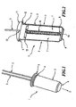
- Fig. 1 shows an embodiment of the electric heating cartridge 1 according to the invention with a housing body 2 and two connection elements 3.
- the housing body 2 is in Fig. 1 by way of example cup-shaped, whereby the heating element 1 is automatically closed at the bottom 4 of the housing body 2.
- the housing body 2 is cylindrical and thus z. B. in a tubular receiving device in a plug E E inserted.
- the heating cartridge 1 can be inserted up to a flange-shaped stopper 5 in the receiving device. Below the stop 5 is located on the housing body 2, a locking means 6 in the form of a hollow bead. By the latching means 6, the heating cartridge 1 is fixed in the receiving device.
- the fixation can be achieved in that the outer diameter of the locking means 6 is greater than the inner diameter of the receiving device, whereby the heating element 1 is frictionally fixed in the receiving device.
- the receiving device has a recess into which the locking means 6 engages positively and thus fixes the heating cartridge 1.
- the locking means 6 is in Fig. 1 exemplified circumferentially on the entire circumference of the housing body 2.
- the latching means 6 is designed, for example, only in sections on the circumference of the housing body 2.
- connection elements 3 e.g. in the form of a plug-in connection, emerge at the top from the housing body 2 for connection of the heating cartridge 1 to a voltage source (not shown).
- connection elements 3 there is also a further possibility of mounting the heating cartridge 1 according to the invention.
- the connection elements 3 are made of a flexibly bendable material.
- the connecting elements 3 serve in this embodiment as fastening elements and the heating cartridge 1 is, hanging on the connecting elements 3, placed directly in the medium to be heated. By manually bending the connection elements 3, the position of the heating cartridge 1 can be varied.
- the housing body 2 is made of a corrosion and acid resistant material, e.g. a metal, made.
- Fig. 2 shows by way of example the embodiment of the heating cartridge 1 according to the invention Fig. 1 in full section 1, whereby the components in the interior of the housing body 2 are visible in the installed state.
- the heating cartridge 1 according to the invention comprises a stack of two pressure bodies 7, an insulating element 8, two electrode bodies 9 and a PTC element 10 in the interior of the housing body 2.
- the PTC element 10 is formed as a thin, preferably rectangular plate with the largest possible Plate surface designed to form a maximum heat conduction surface.
- the PTC element 10 is in a position within the housing body 2, in which it can take the greatest possible length. This position is, for example, a diameter for a housing body with a circular cross section and a diagonal for a body with a polygonal cross section.
- the two Electrode bodies 9 are substantially formed as thin, preferably rectangular plates and have at least the same plate surface as the PTC element 10 so that they can supply the PTG element 10 on the entire plate surface with power and can dissipate the generated heat well.
- the electrode bodies 9 are each connected via a connection element 3 to a voltage source (not shown).
- a connection element 3 to a voltage source (not shown).
- Fig. 2 only one of two connection elements 3 is shown, since the other connection element 3, which connects the second electrode body to the voltage source, is located in the non-illustrated part of the heating cartridge 1.
- the connecting elements 3 and the electrode body 9 may be configured in one piece.
- the insulating 8 isolates the electrode body 9 and the PTC element 10 electrically against the pressure bodies 7 and the housing body 2. But one To ensure good heat conduction from the PTC element 10 and the electrode bodies 9 to the pressure bodies 7, the insulating member 8 is made of a thermally conductive material. In the exemplary embodiment in FIG Fig. 2 the insulating element 8 is made of a polyimide film, in particular of a Kapton film.
- the PTC element 10, the electrode body 9 and the insulating body 8 are sandwiched between the two semicircular pressure bodies 7.
- the pressure bodies 7 are made of a thermally conductive material, e.g. made of aluminum, and are completely on the electrode bodies 9 and on the insulating element 8 at.
- the stack 7, 8, 9, 10 is located in the interior of the housing body 2 and is under a bias, since the width of the stack is greater than the inside diameter of the housing body 2, whereby the wall of the housing body 2 is elastically deflected outwardly and thereby the bias in the interior of the housing body 2 is formed.
- the bias compresses the two pressure body 7 in a direction of action F together.
- the pressure bodies 7 in turn press the insulating element 8, the electrode body 9 and the PTC element 10 together centrally.
- the housing body 2 is closed at the upper end of a closure element 11.
- the closure element 11 seals the housing body 2 in a fluid-tight manner, so that, for example, a fluid to be heated can not get into the interior of the heating cartridge 1.
- the closure element 11 has a widening which, in the installed state, positively engages in the latching means 6 of the housing body 2 and fixes the closure element 11.
- the closure element 11 has a stop flange 12, which rests in the installed state on the stop 5 of the housing body 2.
- the closure element 11 is made of a permanently elastic plastic, namely an elastomer.
- the elastomer also offers the advantage that the closure element is dimensionally stable with respect to temperature fluctuations, does not age and thus does not leak.
- the elastomer can also be cast directly into the housing body 2 and harden therein, whereby an optimal positive connection with the inner surface of the housing body 2 is achieved.
- the closure element 11 has two sealed openings through which the connection elements 3 lead. Alternatively, the closure element 11 may form a part of a fluid-tight plug connection in which a counterpart of the plug connection for supplying power to the heating cartridge can be inserted.
- the connection elements 3 are likewise sealed by the closure element 11.
- the closure element 11 may be made of a corrosion-resistant material for use in corrosive media.
- a holding means 13 is executed on the closure element 11.
- the holding means 13 limits the pressure bodies 7.
- the pressure bodies 7 are thus fixed in their axial position on one side by a shoulder at the end of the housing body 2 and on the other side by the holding means 13 of the closure element 11.
- an air-filled space which forms an insulating layer and a heat loss down, for example when heating a solid, reduced.
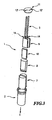
- Fig. 3 shows the electric heating cartridge 1 according to the invention Fig. 1 and 2 in an exploded view.
- the electric heating cartridge 1 comprises the housing body 2 in which the two semicircular pressure bodies 7 are accommodated. Between the two pressure bodies 7 is the PTC element 10, which is surrounded on each side by an electrode body 9, and both are enclosed by the insulating element 8.
- the insulating member 8 in this exemplary illustration is pocket-shaped around the PTC element 10 and the electrode body 9 around. This ensures electrical insulation of the electrode body 9 and the PTC element 10 on five sides.
- PTC element 10 and the electrode body 9 are inserted in the insertion direction E in the pocket-shaped insulating body 8.
- the electrode bodies 9 each comprise a contact element 14 to which the connection element 3 is attached.
- the connection is usually carried out by soldering or welding, but also a pluggable connection is conceivable.
- the heating cartridge 1 is completed by the closure member 11 upwards.
- the individual components are introduced during assembly of the heating element 1 in the insertion direction E in the housing body 2.
Abstract
Description
Die Erfindung betrifft eine elektrische Heizpatrone gemäß dem Oberbegriff von Anspruch 1.The invention relates to an electric heating cartridge according to the preamble of
Heizpatronen dieser Art zeichnen sich durch ihre kleine Bauweise aus und dadurch, dass sie sowohl Heizung als auch gleichzeitig Temperatursteuerung sind. Diese Doppelfunktion wird durch den Einsatz von PTC-Elementen (Positive-Temperature-Coefficient), so genannten Kaltleitern, erreicht. Ein PTC-Element hat die Eigenschaft, nur bis zu einer vorbestimmten Grenztemperatur zu heizen. Ab dieser Grenztemperatur erhöht sich der elektrische Widerstand sprungartig, so dass das PTC-Element nicht weiter heizt. PTC-Elemente sind dadurch selbstregelnd und bedürfen keiner zusätzlichen Temperatursteuerung. Es ist möglich, PTC-Elemente für verschiedene elektrische Spannungen und unterschiedliche Grenztemperaturen herzustellen. Durch eine konstruktiv einfache Bauweise, die im Wesentlichen das eigentliche PTC-Element und zwei Elektrodenkörper umfasst, und eine einfache Stromversorgung über ein zweiadriges Kabel ist die relativ kleine Bauweise der Heizpatronen zu realisieren.Cartridges of this type are characterized by their small construction and the fact that they are both heating and temperature control simultaneously. This dual function is achieved through the use of PTC elements (Positive Temperature Coefficient), so-called PTC thermistors. A PTC element has the property of heating only up to a predetermined limit temperature. From this limit temperature, the electrical resistance increases suddenly, so that the PTC element stops heating. As a result, PTC elements are self-regulating and require no additional temperature control. It is possible to produce PTC elements for different electrical voltages and different limit temperatures. By a structurally simple construction, which essentially comprises the actual PTC element and two electrode body, and a simple power supply via a two-wire cable is to realize the relatively small construction of the heating cartridges.
Durch die beschriebenen Eigenschaften haben Heizpatronen der genannten Art vielfältige Anwendungsbereiche, wie z.B. in der Industrie, der Medizintechnik oder auch im Haushalt. Sie werden beispielsweise in Laminiergeräten, Inhalationsgeräten und in der Automobiltechnik verwendet.Due to the described properties, heating cartridges of the type mentioned have a variety of applications, such as e.g. in industry, medical technology or in the household. They are used, for example, in laminators, inhalers and in the automotive industry.
Eine Heizpatrone aus dem Stand der Technik ist beispielsweise in der
Eine weitere Heizpatrone ist in der
Nachteilig bei der Heizpatrone der
Weitere Heizelemente sind in der
In der
Der Erfindung liegt die Aufgabe zugrunde, eine verbesserte Heizpatrone zu liefern, die in flüssigen oder gasförmigen Medien einsetzbar und vor Verschmutzungen geschützt ist.The invention has for its object to provide an improved heating cartridge, which is used in liquid or gaseous media and protected from contamination.
Diese Aufgabe wird für die eingangs genannte Heizpatrone erfindungsgemäß durch die Merkmale von Anspruch 1 gelöst.This object is achieved according to the invention for the heater cartridge mentioned by the features of
Diese Lösung ist konstruktiv einfach und eine so ausgeführte Heizpatrone kann kostengünstig produziert werden.This solution is structurally simple and such a running heating cartridge can be produced inexpensively.
Durch die von dem Gehäusekörper aufgebrachte Vorspannung werden die Komponenten innerhalb des Gehäusekörpers zusammengedrückt. Hierdurch ist sichergestellt, dass die Wärmeleitflächen von dem Gehäusekörper und den inneren Komponenten aneinander anliegen und dadurch eine zuvor berechnete abzugebende Wärmeenergie an das zu beheizende Medium übertragbar ist. Dadurch, dass im Gegensatz zum Stand der Technik nunmehr der Gehäusekörper als Federelement dient, kann über weite Temperaturbereiche eine gleichmäßige Vorspannkraft erzeugt werden. Überraschenderweise scheint die Temperaturabhängigkeit der vom Gehäusekörper erzeugten Vorspannkraft geringer ausgeprägt zu sein als bei der Ausgestaltung der Isolierkörper als Federelemente. Eine Ursache dafür könnte in der geringen Wandstärke des Gehäusekörpers liegen. Dies gewährleistet ein sicheres Anliegen der Wärmeleitflächen der Komponenten aneinander.The bias applied by the housing body compresses the components within the housing body. This ensures that the heat conduction surfaces of the housing body and the inner components abut each other and thereby a previously calculated heat energy to be delivered is transferable to the medium to be heated. Because, in contrast to the prior art, the housing body now serves as a spring element, a uniform preload force can be generated over wide temperature ranges. Surprisingly, the temperature dependence of the biasing force generated by the housing body seems to be less pronounced than in the embodiment of the insulating body as spring elements. One reason for this could be the small wall thickness of the housing body. This ensures a secure concern the Wärmeleitflächen of the components together.
Dadurch, dass das Isolierelement gegenüber dem Gehäusekörper inelastisch ausgeführt ist, wird die Vorspannung gut auf die Elektrodenkörper und das PTC-Element weitergegeben.Characterized in that the insulating element is made inelastic with respect to the housing body, the bias voltage is well passed to the electrode body and the PTC element.
Die solchermaßen verbesserte Heizvorrichtung kann durch verschiedene, voneinander unabhängige und jeweils für sich vorteilhafte Weiterbildungen weiter entwickelt werden, wie sie im Folgenden erläutert sind.The thus improved heating device can be further developed by various independent and each advantageous developments, as they are explained below.
So kann in einer vorteilhaften Ausgestaltung der Gehäusekörper aus einem elastischen Material ausgestaltet sein. Dies hat den Vorteil, dass der Gehäusekörper elastisch verformbar ist und dadurch die Vorspannung im Inneren des Gehäusekörpers erzeugt werden kann.Thus, in an advantageous embodiment of the housing body made of an elastic material be designed. This has the advantage that the housing body is elastically deformable and thereby the bias can be generated in the interior of the housing body.
Um dem Gehäusekörper eine besonders vorteilhafte Form zu geben, kann der Gehäusekörper im Wesentlichen topfförmig hergestellt sein. Hierdurch muss die erfindungsgemäße Heizpatrone nur an einer Seite verschlossen werden, wodurch sich der Aufwand bei der Montage der Heizpatrone und die Anzahl der Einzelteile reduzieren. Der im Wesentlichen topfförmige Gehäusekörper kann außerdem aus einem dünnwandigen Material hergestellt sein, z.B. durch Tiefziehen. Hierdurch wird zum einen der Gehäusekörper elastischer und zum anderen kann er dadurch die erzeugte Wärmeenergie besser nach außen leiten. Die Form des topfförmigen Gehäusekörpers ist nicht beschränkt und kann z.B. zylindrisch, aber auch vier-, sechs- oder achteckig ausgeführt sein.In order to give the housing body a particularly advantageous shape, the housing body can be made substantially pot-shaped. As a result, the heating cartridge according to the invention must be closed only on one side, thereby reducing the cost of mounting the heating element and the number of items. The substantially cup-shaped housing body may also be made of a thin-walled material, e.g. by deep drawing. As a result, on the one hand, the housing body is elastic and on the other hand, he can thereby better direct the generated heat energy to the outside. The shape of the pot-shaped housing body is not limited and may e.g. be cylindrical, but also four, six or octagonal executed.
Um die Lebensdauer der erfindungsgemäßen Heizpatrone zu erhöhen und ihren möglichen Einsatzbereich zu vergrößern, kann der Gehäusekörper in einer vorteilhaften Weiterbildung aus einem korrosionsbeständigen Material, z.B. einem Metall, gefertigt sein. Um die Heizpatrone außerdem für aggressive flüssige Medien verwenden zu können, kann der Gehäusekörper ferner auch aus einem säurebeständigen Material gefertigt sein.In order to increase the service life of the heating cartridge according to the invention and to increase its possible field of application, the housing body can, in an advantageous development, be made of a corrosion-resistant material, e.g. a metal, be made. In addition, in order to use the heating cartridge for aggressive liquid media, the housing body may also be made of an acid-resistant material.
Ferner ist das mindestens eine Isolierelement aus einer Kunststofffolie gefertigt. Die Kunststofffolie kann eine Polyimidfolie sein. Dies Material eignet sich besonders gut, weil es eine gute elektrische Isolierung bietet und zum anderen besonders wärmeleitfähig ist. Die Polyimidfolie kann beispielsweise eine Kaptonfolie sein. Die Ausgestaltung als dünnwandige Folie verstärkt hierbei die Inelastizität des Isolierelements, so dass die Federkraft nahezu ausschließlich vom Gehäusekörper erzeugt wird.Furthermore, the at least one insulating element is made of a plastic film. The plastic film may be a polyimide film. This material is particularly suitable because it provides good electrical insulation and on the other is particularly thermally conductive. The polyimide film may be, for example, a Kapton film. The design as a thin-walled film in this case enhances the inelasticity of the insulating element, so that the spring force is generated almost exclusively by the housing body.
In einer weiteren vorteilhaften Ausgestaltung können die Elektrodenkörper jeweils ein Kontaktelement aufweisen, durch das die Elektrodenkörper an eine Spannungsquelle anschließbar sind. Die Kontaktelemente können als ein Schweißkontakt oder auch als ein Stecker ausgeführt sein, um eine gute Anschlussmöglichkeit zu bieten. Die Elektrodenkörper sind ferner üblicherweise aus einem wärmeleitfähigen Material, insbesondere einem Metall, hergestellt.In a further advantageous embodiment, the electrode body can each have a contact element, by which the electrode body can be connected to a voltage source. The contact elements may be designed as a welding contact or as a plug to provide a good connection option. The electrode bodies are also usually made of a thermally conductive material, in particular a metal.
In einer vorteilhaften Weiterbildung kann die erfindungsgemäße Heizpatrone wenigstens zwei wärmeleitende Druckkörper aufweisen, die eine Federkraft von dem Gehäusekörper in Richtung des mindestens einem PTC-Elements übertragend ausgeformt sind. Dies hat den Vorteil, dass die Druckkörper aus einem kostengünstigen, leicht zu fertigenden wärmeleitfähigen Material, z.B. stranggepresstes Aluminium, hergestellt sein können und so den Gehäusekörper ausfüllen, Wärme übertragen und die Federkraft nach innen leiten. Die kosteneffektiven Komponenten, wie PTC-Element, Elektrodenkörper und Isolierelement können hierdurch kleiner und dadurch materialsparend ausgeführt sein, was zur Reduzierung der Materialkosten führt. Die Druckkörper können insbesondere zwischen dem Gehäusekörper und dem PTC-Element angeordnet sein. Sie können ferner das PTC-Element sandwichartig umgeben. Ferner können die Druckkörper als Elektrodenkörper ausgestaltet sein. Sie können in einer Weiterbildung auch von dem Isolierelement umgeben sein.In an advantageous development, the heating cartridge according to the invention may comprise at least two heat-conducting pressure bodies, which are formed by a spring force transferring from the housing body in the direction of at least one PTC element. This has the advantage that the pressure bodies are made of a low cost, easy to produce thermally conductive material, e.g. made of extruded aluminum, can be made and so fill the housing body, transfer heat and conduct the spring force inward. The cost-effective components, such as PTC element, electrode body and insulating element can thereby be made smaller and thus save material, which leads to the reduction of material costs. The pressure bodies can in particular be arranged between the housing body and the PTC element. You can also sandwich the PTC element. Furthermore, the pressure bodies can be designed as electrode body. You may also be surrounded by the insulating in a development.
Ferner kann die Breite eines Stapels aus den Druckkörpern, dem wenigstens einen Isolierelement, den Elektrodenkörpern und dem mindestens einen PTC-Element in einer vorteilhaften Weiterbildung größer sein als die lichte Weite des Gehäusekörpers. Hierdurch wird beim Einschieben des Stapels in den Gehäusekörper während der Montage der Heizpatrone der Gehäusekörper elastisch aufgeweitet. Durch diese elastische Aufweitung wird die gewünschte Vorspannung im Inneren der Heizpatrone erzeugt. Durch die Größe des Übermaßes von der Breite des Stapels und der lichten Weite des Gehäusekörpers kann die Größe der Vorspannung vorbestimmt werden. Um sicherzustellen, dass die Vorspannkraft im Wesentlichen oder nahezu ausschließlich vom Gehäusekörper erzeugt wird, ist, unter Berücksichtigung der jeweiligen Dicken, die Elastizität der Druckkörper kleiner bemessen als die des Gehäusekörpers. Aufgrund der höheren Elastizität bleiben die Druckkörper unter Wirkung der Vorspannkraft daher im Wesentlichen unverformt.Furthermore, the width of a stack of the pressure bodies, the at least one insulating element, the electrode bodies and the at least one PTC element in an advantageous development can be greater than the inside diameter of the housing body. As a result, during the assembly of the heating cartridge, the housing body is elastically expanded when the stack is inserted into the housing body. This elastic expansion creates the desired preload inside the heating cartridge. By the size of the excess of the width of the stack and the clear width of the case body, the magnitude of the bias voltage can be predetermined. To ensure that the biasing force is generated substantially or almost exclusively by the housing body, taking into account the respective thicknesses, the elasticity of the pressure body is dimensioned smaller than that of the housing body. Due to the higher elasticity, the pressure bodies remain under the action of the biasing force therefore substantially undeformed.
In einer weiteren vorteilhaften Ausgestaltung kann die Heizpatrone mindestens ein Verschlusselement aufweisen, durch das der Gehäusekörper im Wesentlichen fluiddicht verschlossen ist. Hierdurch ist ein Einsatz der erfindungsgemäßen Heizpatrone in flüssigen oder gasförmigen Medien möglich. Das Innere des Gehäusekörpers der erfindungsgemäßen Heizpatrone ist so außerdem vor Verschmutzung geschützt, wodurch ein Einsatz auch in sehr schmutzigen Umgebungen möglich ist.In a further advantageous embodiment, the heating cartridge may have at least one closure element, by which the housing body is substantially closed fluid-tight. This makes it possible to use the heating cartridge according to the invention in liquid or gaseous media. The interior of the housing body of the heating cartridge according to the invention is thus also protected against contamination, whereby a use in very dirty environments is possible.
Außerdem kann das Verschlusselement in einer weiteren vorteilhaften Ausgestaltung aus einem dauerelastischen Material, insbesondere einem Elastomer, hergestellt sein. Dies ist von Vorteil, weil dauerelastisches Material alterungsbeständig ist und auch bei Temperaturschwankungen weder bricht noch porös wird. Zum Einsatz in korrosiven, alkalischen und/oder säurehaltigen Fluiden kann das Verschlusselement entsprechend korrosions- und/oder säurebeständig ausgestaltet sein.In addition, the closure element may be made in a further advantageous embodiment of a permanently elastic material, in particular an elastomer. This is advantageous because permanently elastic material is resistant to aging and does not break or become porous even with temperature fluctuations. For use in corrosive, alkaline and / or acidic fluids, the closure element can be designed to be resistant to corrosion and / or acid.
In einer weiteren vorteilhaften Ausgestaltung kann der Gehäusekörper mit einem Rastmittel ausgestaltet sein, in das das Verschlusselement mit einer entsprechenden Gegenraste formschlüssig einrastet. Hierdurch wird das Verschlusselement auf einfache Weise in dem Gehäusekörper fixiert. Ferner kann durch die außenseitige Verwendung des Rastmittels der Gehäusekörper z.B. in eine rohrförmige Aufnahmeeinrichtung befestigt werden. Durch das Rastmittel wird der Gehäusekörper und damit die Heizpatrone durch Reibschluss oder Formschluss in der Aufnahmeeinrichtung gehalten.In a further advantageous embodiment, the housing body may be configured with a latching means into which the closure element engages positively with a corresponding mating catch. As a result, the closure element is fixed in a simple manner in the housing body. Furthermore, by the outside use of the locking means of the housing body, for example, in a tubular receiving device be attached. By the latching means of the housing body and thus the heating cartridge is held by frictional engagement or positive engagement in the receiving device.
Um die Komponenten im Inneren des Gehäusekörpers gegen ein Verschieben zu sichern, kann das Verschlusselement in einer vorteilhaften Weiterbildung mit einem Haltemittel ausgestaltet sein, das die Druckkörper axial sichernd ausgeformt ist.In order to secure the components in the interior of the housing body against displacement, the closure element can be configured in an advantageous development with a holding means which is formed axially securing the pressure body.
In einer weiteren vorteilhaften Ausgestaltung kann die Heizpatrone mindestens ein Anschlusselement umfassen, durch das die Elektrodenkörper mit einer Spannungsquelle verbindbar sind. Hierdurch wird eine einfache Möglichkeit geschaffen, die erfindungsgemäße Heizpatrone mit Strom zu versorgen. Ferner kann das mindestens eine Anschlusselement auch als ein Befestigungselement ausgeführt sein und die Heizpatrone in dem zu beheizenden Medium halten. Hierdurch kann die Heizpatrone z.B. beim Heizen eines flüssigen Mediums direkt und ohne Aufnahmeeinrichtung in diesem angebracht werden, gehalten durch das Anschlusselement.In a further advantageous embodiment, the heating cartridge may comprise at least one connection element, by which the electrode body can be connected to a voltage source. As a result, a simple way is provided to supply the heating element according to the invention with electricity. Furthermore, the at least one connecting element can also be designed as a fastening element and hold the heating cartridge in the medium to be heated. As a result, the heating cartridge, e.g. when heating a liquid medium directly and without receiving means are mounted in this, held by the connecting element.
In einer weiteren vorteilhaften Ausgestaltung kann das Verschlusselement mindestens eine abgedichtete Öffnung aufweisen, durch die sich jeweils ein Anschlusselement erstreckt. Dies hat den Vorteil, dass das PTC-Element mit Strom versorgt werden kann, ohne dass die erfinderische Heizpatrone undicht wird. Alternativ kann das Verschlusselement als ein Teil einer Steckverbindung ausgeformt sein, in die beispielsweise ein Steckerelement zur Stromversorgung der Heizpatrone einsteckbar ist. Vorteilhafterweise ist die Steckverbindung zum Einsatz der Heizpatrone in Flüssigkeiten fluiddicht ausgeführt.In a further advantageous embodiment, the closure element may have at least one sealed opening through which a respective connection element extends. This has the advantage that the PTC element can be supplied with power without the inventive heating cartridge is leaking. Alternatively, the closure element may be formed as a part of a plug-in connection into which, for example, a plug element for supplying power to the heating cartridge can be inserted. Advantageously, the plug connection for the use of the immersion heater in liquids is designed to be fluid-tight.
Im Folgenden wird die Erfindung beispielhaft mit Bezug auf die beigefügten Zeichnungen erläutert. Die unterschiedlichen Merkmale können dabei unabhängig voneinander kombiniert werden, wie dies oben bei den einzelnen vorteilhaften Ausgestaltungen bereits dargelegt wurde.The invention will now be described by way of example with reference to the accompanying drawings. The different features can be combined independently of each other, as has already been explained above in the individual advantageous embodiments.
Es zeigen:
- Fig. 1
- eine Ausführungsform der erfindungsgemäßen elektrischen Heizpatrone in einer schematischen Perspektivansicht;
- Fig. 2
- die Ausführungsform der elektrischen Heizpatrone aus
Fig. 1 im Vollschnitt; - Fig.3
- die Ausführungsform der elektrischen Heizvorrichtung aus
Fig. 1 in einer Explosionsdarstellung.
- Fig. 1
- an embodiment of the electric heating element according to the invention in a schematic perspective view;
- Fig. 2
- the embodiment of the electric heating cartridge
Fig. 1 in full section; - Figure 3
- the embodiment of the electric heater
Fig. 1 in an exploded view.
Die zwei Anschlusselemente 3, z.B. in Form einer Steckverbindung, treten oben aus dem Gehäusekörper 2 zum Anschluss der Heizpatrone 1 an eine Spannungsquelle (nicht dargestellt) heraus. Durch die Anschlusselemente 3 besteht außerdem eine weitere Befestigungsmöglichkeit der erfindungsgemäßen Heizpatrone 1. Hierfür sind die Anschlusselemente 3 aus einem flexibel biegbaren Material hergestellt. Die Anschlusselemente 3 dienen bei dieser Ausgestaltung als Befestigungselemente und die Heizpatrone 1 wird, an den Anschlusselementen 3 hängend, direkt in dem zu beheizenden Medium platziert. Durch ein manuelles Verbiegen der Anschlusselementen 3 kann die Position der Heizpatrone 1 variiert werden.The two
Damit die Heizpatrone 1 auch zum Beheizen von aggressiven Medien einsetzbar ist, ist der Gehäusekörper 2 aus einem korrosions- und säurebeständigen Material, z.B. einem Metall, hergestellt.In order for the
An den beiden Plattenflächen des PTGElements 10 liegen zwei Elektrodenkörpern 9 an. Die beiden Elektrodenkörper 9 sind im Wesentlichen als dünne, vorzugsweise rechteckige Platten ausgeformt und haben mindestens die gleiche Plattenfläche wie das PTC-Element 10, damit sie das PTG-Element 10 auf dessen gesamter Plattenfläche mit Strom versorgen und die erzeugte Wärme gut ableiten können. Die Elektrodenkörper 9 sind jeweils über ein Anschlusselement 3 mit einer Spannungsquelle (nicht dargestellt) verbunden. In
Um die Elektrodenkörper 9 mitsamt dem PTC-Element 10 herum ist das im Vergleich zum Gehäusekörper 2 inelastische, folienförmige Isolierelement 8. Das Isolierelement 8 isoliert die Elektrodenkörper 9 und das PTC-Element 10 elektrisch gegenüber den Druckkörpern 7 und dem Gehäusekörper 2. Um aber eine gute Wärmeleitung vom PTC-Element 10 bzw. den Elektrodenkörpern 9 zu den Druckkörpern 7 zu gewährleisten, ist das Isolierelement 8 aus einem wärmeleitenden Material hergestellt. Bei der beispielhaften Ausführungsform in
Das PTC-Element 10, die Elektrodenkörper 9 und der Isolierkörper 8 sind zwischen den beiden halbkreisförmigen Druckkörpern 7 sandwichartig angeordnet. Die Druckkörper 7 sind für eine gute Wärmeübertragung aus einem wärmeleitfähigen Material, z.B. aus Aluminium, gefertigt und liegen vollständig an den Elektrodenkörpern 9 bzw. an dem Isolierelement 8 an. Der Stapel 7, 8, 9, 10 befindet sich im Inneren des Gehäusekörpers 2 und steht unter einer Vorspannung, da die Breite des Stapels größer ist als die lichte Weite des Gehäusekörpers 2, wodurch die Wandung des Gehäusekörpers 2 elastisch nach außen ausgelenkt wird und dadurch die Vorspannung im Inneren des Gehäusekörpers 2 entsteht. Die Vorspannung drückt die beiden Druckkörper 7 in einer Wirkrichtung F zusammen. Die Druckkörper 7 drücken wiederum das Isolierelement 8, die Elektrodenkörper 9 und das PTC-Element 10 zentrisch zusammen. Durch das Zusammendrücken durch die Vorspannung im Inneren des Gehäusekörpers 2 ist sichergestellt, dass beispielsweise Luftspalte, die möglicherweise durch Fertigungstoleranzen der einzelnen Bauteile oder durch unterschiedliche Wärmeausdehnungen entstehen, zuverlässig weggedrückt werden, wodurch eine gute Wärmeleitung innerhalb der erfindungsgemäßen Heizpatrone 1 gewährleistet ist.The
Wie in
Um ein Verrutschen der Druckkörper 7 im Inneren des Gehäusekörpers 2 zu verhindern, ist an dem Verschlusselement 11 ein Haltemittel 13 ausgeführt. Im eingebauten Zustand begrenzt das Haltemittel 13 die Druckkörper 7. Die Druckkörper 7 sind also in ihrer axialen Position auf der einen Seite durch einen Absatz am Ende des Gehäusekörpers 2 und auf der anderen Seite durch das Haltemittel 13 des Verschlusselementes 11 fixiert.In order to prevent slippage of the
Am Boden 4 des Gehäusekörpers 2 befindet sich zwischen Gehäusekörper 2 und den Druckkörpern 7 ein luftgefüllter Freiraum, der eine Isolierschicht bildet und eine Wärmeabgabe nach unten, beispielsweise beim Beheizen eines Festkörpers, reduziert.At the bottom 4 of the
Wie in
Claims (10)
- An electrical heating cartridge (1) for heating liquid and/or gaseous media, having at least one PTC element (10), two electrode bodies (9) assigned to the at least one PTC element (10) which are accommodated in an essentially cup-shaped housing body (2) electrically insulated from the electrode bodies (9) by means of at least one insulating element (8) and compressed under pretensioning, the housing body (2) being in the form of a spring element producing the pretensioning and the at least one insulating element (8), which is produced from a synthetic film, being designed to be inelastic with respect to the housing body (2), and having at least two heat-conducting pressure bodies (7) which are shaped to transfer the pretensioning from the housing body (2) towards the at least one PTC element (10), characterised in that there is an air-filled free space located on a base (4) of the housing body (2) between the housing body (2) and the pressure bodies (7) forming an insulating layer, that the heating cartridge (1) has at least one closure element (11) made of a permanently elastic material by means of which the housing body (2) is sealed off in a substantially liquid tight manner and which is designed with a holding means (13) shaped to secure the pressure bodies (7) axially and has at least one sealed opening through which a respective connection element (3) extends, that the housing body (2) is designed with a securing means (6) in which the closure element (11) engages, with form locking, with a counter-detent, and that the pressure bodies (7) are fixed in their axial position on the one side by means of a shoulder on the end of the housing body (2) and on the other side by the holding means (13).
- The electrical heating cartridge (1) according to Claim 1, characterised in that the housing body (2) is produced from an elastic material.
- The electrical heating cartridge (1) according to Claim 1 or 2, characterised in that the housing body (2) is produced substantially in a cup-shape.
- The electrical heating cartridge (1) according to any of the claims specified above, characterised in that the housing body (2) is produced from a corrosion-resistant material.
- The electrical heating cartridge (1) according to Claim 4, characterised in that the synthetic film is a polyimide film.
- The electrical heating cartridge (1) according to any of the claims specified above, characterised in that the electrode bodies (9) respectively have a contact element (14) by means of which the electrode bodies (9) can be connected to a voltage source.
- The electrical heating cartridge (1) according to Claim 1, characterised in that the width of a stack comprising the pressure bodies (7), the at least one insulating element (8), the electrode bodies (9) and the at least one PTC element (10) is larger than the inner width of the housing body (2).
- The electrical heating cartridge (1) according to Claim 1 or 7, characterised in that the at least two pressure bodies (7) are produced from aluminium.
- The electrical heating cartridge (1) according to any of the claims specified above, characterised in that the heating cartridge (1) comprises at least one connection element (3) which is designed as a fixing element by means of which the heating cartridge (1) can be attached within the medium to be heated.
- The electrical heating cartridge (1) according to any of the claims specified above, characterised in that as regards the pretensioning force, the pressure bodies (7) are designed to be less flexible than the housing body (2).
Priority Applications (3)
| Application Number | Priority Date | Filing Date | Title |
|---|---|---|---|
| AT03020876T ATE318065T1 (en) | 2003-09-15 | 2003-09-15 | ELECTRIC HEATER CARTRIDGE |
| EP03020876A EP1523224B2 (en) | 2003-09-15 | 2003-09-15 | Electrical heating cartridge |
| DE50302406T DE50302406D1 (en) | 2003-09-15 | 2003-09-15 | Electric heating cartridge |
Applications Claiming Priority (1)
| Application Number | Priority Date | Filing Date | Title |
|---|---|---|---|
| EP03020876A EP1523224B2 (en) | 2003-09-15 | 2003-09-15 | Electrical heating cartridge |
Publications (3)
| Publication Number | Publication Date |
|---|---|
| EP1523224A1 EP1523224A1 (en) | 2005-04-13 |
| EP1523224B1 EP1523224B1 (en) | 2006-02-15 |
| EP1523224B2 true EP1523224B2 (en) | 2009-11-11 |
Family
ID=34306770
Family Applications (1)
| Application Number | Title | Priority Date | Filing Date |
|---|---|---|---|
| EP03020876A Expired - Lifetime EP1523224B2 (en) | 2003-09-15 | 2003-09-15 | Electrical heating cartridge |
Country Status (3)
| Country | Link |
|---|---|
| EP (1) | EP1523224B2 (en) |
| AT (1) | ATE318065T1 (en) |
| DE (1) | DE50302406D1 (en) |
Cited By (2)
| Publication number | Priority date | Publication date | Assignee | Title |
|---|---|---|---|---|
| DE102010063939A1 (en) | 2010-12-22 | 2012-06-28 | Mahle International Gmbh | Electrical heating device for e.g. fuel filter of diesel water separator in motor car, has ceramic layer and/or contact layer chosen according to composition and/or thickness of heating element having predefined electric resistance value |
| US20210354530A1 (en) * | 2020-05-15 | 2021-11-18 | Eberspächer Catem Gmbh & Co. Kg | PTC Heating Assembly and Method for Manufacturing the Same |
Families Citing this family (3)
| Publication number | Priority date | Publication date | Assignee | Title |
|---|---|---|---|---|
| DE102010006184A1 (en) * | 2010-01-29 | 2011-08-04 | Eichenauer Heizelemente GmbH & Co. KG, 76870 | An electric heater and method of manufacturing an electric heater |
| WO2019079302A1 (en) | 2017-10-19 | 2019-04-25 | Tom Richards, Inc. | Heat transfer assembly |
| CN111265244A (en) * | 2018-12-05 | 2020-06-12 | 深圳迈瑞生物医疗电子股份有限公司 | Couplant heating device and ultrasonic equipment |
Family Cites Families (7)
| Publication number | Priority date | Publication date | Assignee | Title |
|---|---|---|---|---|
| US2360267A (en) * | 1942-11-23 | 1944-10-10 | Mcgraw Electric Co | Encased heating unit |
| US4822980A (en) * | 1987-05-04 | 1989-04-18 | Gte Products Corporation | PTC heater device |
| DE9200944U1 (en) * | 1992-01-28 | 1992-03-19 | Tuerk & Hillinger Gmbh, 7200 Tuttlingen, De | |
| JPH07263122A (en) * | 1994-03-22 | 1995-10-13 | Nichicon Corp | Heating device |
| DE19737241C2 (en) * | 1997-08-27 | 1999-09-30 | Tuerk & Hillinger Gmbh | Electrical, compressed radiator equipped with PTC elements |
| DE20121116U1 (en) * | 2001-12-21 | 2003-04-24 | Eichenauer Gmbh & Co Kg F | Electric heating device for heating a liquid in a motor vehicle |
| DE20212580U1 (en) * | 2002-08-16 | 2002-10-10 | Tuerk & Hillinger Gmbh | Electric heating cartridge with PTC elements |
-
2003
- 2003-09-15 EP EP03020876A patent/EP1523224B2/en not_active Expired - Lifetime
- 2003-09-15 AT AT03020876T patent/ATE318065T1/en not_active IP Right Cessation
- 2003-09-15 DE DE50302406T patent/DE50302406D1/en not_active Expired - Lifetime
Cited By (2)
| Publication number | Priority date | Publication date | Assignee | Title |
|---|---|---|---|---|
| DE102010063939A1 (en) | 2010-12-22 | 2012-06-28 | Mahle International Gmbh | Electrical heating device for e.g. fuel filter of diesel water separator in motor car, has ceramic layer and/or contact layer chosen according to composition and/or thickness of heating element having predefined electric resistance value |
| US20210354530A1 (en) * | 2020-05-15 | 2021-11-18 | Eberspächer Catem Gmbh & Co. Kg | PTC Heating Assembly and Method for Manufacturing the Same |
Also Published As
| Publication number | Publication date |
|---|---|
| EP1523224A1 (en) | 2005-04-13 |
| DE50302406D1 (en) | 2006-04-20 |
| ATE318065T1 (en) | 2006-03-15 |
| EP1523224B1 (en) | 2006-02-15 |
Similar Documents
| Publication | Publication Date | Title |
|---|---|---|
| EP1525426B1 (en) | Microstructured apparatus for heating and atomizing a fluid | |
| EP2428746B2 (en) | Heat exchanger | |
| DE2948591C2 (en) | ||
| DE2804749C3 (en) | Water heater | |
| EP0194507B1 (en) | Heating element for heating streaming, especially gaseous media | |
| EP0282085B1 (en) | Heating element for fluids | |
| DE10258257B4 (en) | Electric heating device for heating a liquid in a motor vehicle | |
| DE102009058159B4 (en) | Filter device for fluids with an electric heater and heater for a filter device | |
| EP3273177B1 (en) | Electric heating device | |
| DE2551980A1 (en) | SEALED THERMOSTATIC HEATING DEVICE | |
| EP1777452A2 (en) | Heatable connector | |
| EP2355614B1 (en) | Electric heater and method for producing same | |
| EP1523224B2 (en) | Electrical heating cartridge | |
| EP1529470B2 (en) | Heating modul with heating surface and continuous flow heater and production method thereof | |
| EP1557601B1 (en) | Heating clip for a fluid conduit | |
| DE102012109768A1 (en) | Radiator element for electric heater, for heating air current in combustion engine of motor vehicle, has fin element comprising curved corrugated fins that are electrically connected to contact element by screw made of hard material | |
| DE102021112690A1 (en) | PTC heating device and process for their manufacture | |
| WO2011101312A2 (en) | Heating arrangement | |
| EP0718738A2 (en) | Thermostatic operational element with an electric resistive heating element | |
| EP3424266B1 (en) | Heating cartridge with a protective tube | |
| DE102009054654A1 (en) | Metering module for exhaust gas after-treatment system of motor vehicle, has valve with tip held in housing fastened to flange, insulating device arranged between housing and flange, and insulating element arranged between tip and housing | |
| EP2458191A1 (en) | Heating device | |
| EP1510688B1 (en) | Heating device for a medium to be heated | |
| DE3730195C2 (en) | ||
| DE8507557U1 (en) | Heating element for heating flowing, especially gaseous media |
Legal Events
| Date | Code | Title | Description |
|---|---|---|---|
| PUAI | Public reference made under article 153(3) epc to a published international application that has entered the european phase |
Free format text: ORIGINAL CODE: 0009012 |
|
| 17P | Request for examination filed |
Effective date: 20040503 |
|
| AK | Designated contracting states |
Kind code of ref document: A1 Designated state(s): AT BE BG CH CY CZ DE DK EE ES FI FR GB GR HU IE IT LI LU MC NL PT RO SE SI SK TR |
|
| AX | Request for extension of the european patent |
Extension state: AL LT LV MK |
|
| RAP1 | Party data changed (applicant data changed or rights of an application transferred) |
Owner name: DBK DAVID + BAADER GMBH |
|
| GRAP | Despatch of communication of intention to grant a patent |
Free format text: ORIGINAL CODE: EPIDOSNIGR1 |
|
| GRAS | Grant fee paid |
Free format text: ORIGINAL CODE: EPIDOSNIGR3 |
|
| GRAA | (expected) grant |
Free format text: ORIGINAL CODE: 0009210 |
|
| AKX | Designation fees paid |
Designated state(s): AT BE BG CH CY CZ DE DK EE ES FI FR GB GR HU IE IT LI LU MC NL PT RO SE SI SK TR |
|
| AK | Designated contracting states |
Kind code of ref document: B1 Designated state(s): AT BE BG CH CY CZ DE DK EE ES FI FR GB GR HU IE IT LI LU MC NL PT RO SE SI SK TR |
|
| PG25 | Lapsed in a contracting state [announced via postgrant information from national office to epo] |
Ref country code: IT Free format text: LAPSE BECAUSE OF FAILURE TO SUBMIT A TRANSLATION OF THE DESCRIPTION OR TO PAY THE FEE WITHIN THE PRESCRIBED TIME-LIMIT;WARNING: LAPSES OF ITALIAN PATENTS WITH EFFECTIVE DATE BEFORE 2007 MAY HAVE OCCURRED AT ANY TIME BEFORE 2007. THE CORRECT EFFECTIVE DATE MAY BE DIFFERENT FROM THE ONE RECORDED. Effective date: 20060215 Ref country code: RO Free format text: LAPSE BECAUSE OF FAILURE TO SUBMIT A TRANSLATION OF THE DESCRIPTION OR TO PAY THE FEE WITHIN THE PRESCRIBED TIME-LIMIT Effective date: 20060215 Ref country code: IE Free format text: LAPSE BECAUSE OF FAILURE TO SUBMIT A TRANSLATION OF THE DESCRIPTION OR TO PAY THE FEE WITHIN THE PRESCRIBED TIME-LIMIT Effective date: 20060215 Ref country code: SK Free format text: LAPSE BECAUSE OF FAILURE TO SUBMIT A TRANSLATION OF THE DESCRIPTION OR TO PAY THE FEE WITHIN THE PRESCRIBED TIME-LIMIT Effective date: 20060215 Ref country code: SI Free format text: LAPSE BECAUSE OF FAILURE TO SUBMIT A TRANSLATION OF THE DESCRIPTION OR TO PAY THE FEE WITHIN THE PRESCRIBED TIME-LIMIT Effective date: 20060215 Ref country code: NL Free format text: LAPSE BECAUSE OF FAILURE TO SUBMIT A TRANSLATION OF THE DESCRIPTION OR TO PAY THE FEE WITHIN THE PRESCRIBED TIME-LIMIT Effective date: 20060215 Ref country code: GB Free format text: LAPSE BECAUSE OF FAILURE TO SUBMIT A TRANSLATION OF THE DESCRIPTION OR TO PAY THE FEE WITHIN THE PRESCRIBED TIME-LIMIT Effective date: 20060215 Ref country code: FI Free format text: LAPSE BECAUSE OF FAILURE TO SUBMIT A TRANSLATION OF THE DESCRIPTION OR TO PAY THE FEE WITHIN THE PRESCRIBED TIME-LIMIT Effective date: 20060215 |
|
| REG | Reference to a national code |
Ref country code: CH Ref legal event code: EP Ref country code: GB Ref legal event code: FG4D Free format text: NOT ENGLISH |
|
| REG | Reference to a national code |
Ref country code: IE Ref legal event code: FG4D Free format text: LANGUAGE OF EP DOCUMENT: GERMAN |
|
| REF | Corresponds to: |
Ref document number: 50302406 Country of ref document: DE Date of ref document: 20060420 Kind code of ref document: P |
|
| PG25 | Lapsed in a contracting state [announced via postgrant information from national office to epo] |
Ref country code: DK Free format text: LAPSE BECAUSE OF FAILURE TO SUBMIT A TRANSLATION OF THE DESCRIPTION OR TO PAY THE FEE WITHIN THE PRESCRIBED TIME-LIMIT Effective date: 20060515 Ref country code: SE Free format text: LAPSE BECAUSE OF FAILURE TO SUBMIT A TRANSLATION OF THE DESCRIPTION OR TO PAY THE FEE WITHIN THE PRESCRIBED TIME-LIMIT Effective date: 20060515 Ref country code: BG Free format text: LAPSE BECAUSE OF FAILURE TO SUBMIT A TRANSLATION OF THE DESCRIPTION OR TO PAY THE FEE WITHIN THE PRESCRIBED TIME-LIMIT Effective date: 20060515 |
|
| PG25 | Lapsed in a contracting state [announced via postgrant information from national office to epo] |
Ref country code: ES Free format text: LAPSE BECAUSE OF FAILURE TO SUBMIT A TRANSLATION OF THE DESCRIPTION OR TO PAY THE FEE WITHIN THE PRESCRIBED TIME-LIMIT Effective date: 20060526 |
|
| PG25 | Lapsed in a contracting state [announced via postgrant information from national office to epo] |
Ref country code: PT Free format text: LAPSE BECAUSE OF FAILURE TO SUBMIT A TRANSLATION OF THE DESCRIPTION OR TO PAY THE FEE WITHIN THE PRESCRIBED TIME-LIMIT Effective date: 20060717 |
|
| NLV1 | Nl: lapsed or annulled due to failure to fulfill the requirements of art. 29p and 29m of the patents act | ||
| GBV | Gb: ep patent (uk) treated as always having been void in accordance with gb section 77(7)/1977 [no translation filed] |
Effective date: 20060215 |
|
| REG | Reference to a national code |
Ref country code: IE Ref legal event code: FD4D |
|
| PG25 | Lapsed in a contracting state [announced via postgrant information from national office to epo] |
Ref country code: BE Free format text: LAPSE BECAUSE OF NON-PAYMENT OF DUE FEES Effective date: 20060930 Ref country code: MC Free format text: LAPSE BECAUSE OF NON-PAYMENT OF DUE FEES Effective date: 20060930 |
|
| PLBI | Opposition filed |
Free format text: ORIGINAL CODE: 0009260 |
|
| PLAX | Notice of opposition and request to file observation + time limit sent |
Free format text: ORIGINAL CODE: EPIDOSNOBS2 |
|
| 26 | Opposition filed |
Opponent name: TUERK & HILLINGER GMBH Effective date: 20061111 Opponent name: EICHENAUER HEIZELEMENTE GMBH & CO.KG Effective date: 20061115 |
|
| EN | Fr: translation not filed | ||
| PLBB | Reply of patent proprietor to notice(s) of opposition received |
Free format text: ORIGINAL CODE: EPIDOSNOBS3 |
|
| PG25 | Lapsed in a contracting state [announced via postgrant information from national office to epo] |
Ref country code: AT Free format text: LAPSE BECAUSE OF NON-PAYMENT OF DUE FEES Effective date: 20060915 |
|
| BERE | Be: lapsed |
Owner name: DBK DAVID + BAADER G.M.B.H. Effective date: 20060930 |
|
| PG25 | Lapsed in a contracting state [announced via postgrant information from national office to epo] |
Ref country code: FR Free format text: LAPSE BECAUSE OF FAILURE TO SUBMIT A TRANSLATION OF THE DESCRIPTION OR TO PAY THE FEE WITHIN THE PRESCRIBED TIME-LIMIT Effective date: 20070105 |
|
| PG25 | Lapsed in a contracting state [announced via postgrant information from national office to epo] |
Ref country code: GR Free format text: LAPSE BECAUSE OF FAILURE TO SUBMIT A TRANSLATION OF THE DESCRIPTION OR TO PAY THE FEE WITHIN THE PRESCRIBED TIME-LIMIT Effective date: 20060516 Ref country code: CZ Free format text: LAPSE BECAUSE OF FAILURE TO SUBMIT A TRANSLATION OF THE DESCRIPTION OR TO PAY THE FEE WITHIN THE PRESCRIBED TIME-LIMIT Effective date: 20060215 |
|
| REG | Reference to a national code |
Ref country code: CH Ref legal event code: PL |
|
| PG25 | Lapsed in a contracting state [announced via postgrant information from national office to epo] |
Ref country code: EE Free format text: LAPSE BECAUSE OF FAILURE TO SUBMIT A TRANSLATION OF THE DESCRIPTION OR TO PAY THE FEE WITHIN THE PRESCRIBED TIME-LIMIT Effective date: 20060215 |
|
| PG25 | Lapsed in a contracting state [announced via postgrant information from national office to epo] |
Ref country code: CH Free format text: LAPSE BECAUSE OF NON-PAYMENT OF DUE FEES Effective date: 20070930 Ref country code: HU Free format text: LAPSE BECAUSE OF FAILURE TO SUBMIT A TRANSLATION OF THE DESCRIPTION OR TO PAY THE FEE WITHIN THE PRESCRIBED TIME-LIMIT Effective date: 20060816 Ref country code: TR Free format text: LAPSE BECAUSE OF FAILURE TO SUBMIT A TRANSLATION OF THE DESCRIPTION OR TO PAY THE FEE WITHIN THE PRESCRIBED TIME-LIMIT Effective date: 20060215 Ref country code: LU Free format text: LAPSE BECAUSE OF NON-PAYMENT OF DUE FEES Effective date: 20060915 Ref country code: LI Free format text: LAPSE BECAUSE OF NON-PAYMENT OF DUE FEES Effective date: 20070930 |
|
| PG25 | Lapsed in a contracting state [announced via postgrant information from national office to epo] |
Ref country code: FR Free format text: LAPSE BECAUSE OF FAILURE TO SUBMIT A TRANSLATION OF THE DESCRIPTION OR TO PAY THE FEE WITHIN THE PRESCRIBED TIME-LIMIT Effective date: 20060215 Ref country code: CY Free format text: LAPSE BECAUSE OF FAILURE TO SUBMIT A TRANSLATION OF THE DESCRIPTION OR TO PAY THE FEE WITHIN THE PRESCRIBED TIME-LIMIT Effective date: 20060215 |
|
| PUAH | Patent maintained in amended form |
Free format text: ORIGINAL CODE: 0009272 |
|
| STAA | Information on the status of an ep patent application or granted ep patent |
Free format text: STATUS: PATENT MAINTAINED AS AMENDED |
|
| 27A | Patent maintained in amended form |
Effective date: 20091111 |
|
| AK | Designated contracting states |
Kind code of ref document: B2 Designated state(s): AT BE BG CH CY CZ DE DK EE ES FI FR GB GR HU IE IT LI LU MC NL PT RO SE SI SK TR |
|
| REG | Reference to a national code |
Ref country code: ES Ref legal event code: FD2A Effective date: 20060916 |
|
| PGFP | Annual fee paid to national office [announced via postgrant information from national office to epo] |
Ref country code: DE Payment date: 20090921 Year of fee payment: 7 |
|
| REG | Reference to a national code |
Ref country code: DE Ref legal event code: R119 Ref document number: 50302406 Country of ref document: DE Effective date: 20110401 |
|
| PG25 | Lapsed in a contracting state [announced via postgrant information from national office to epo] |
Ref country code: DE Free format text: LAPSE BECAUSE OF NON-PAYMENT OF DUE FEES Effective date: 20110401 |