EP2458191A1 - Heating device - Google Patents
Heating device Download PDFInfo
- Publication number
- EP2458191A1 EP2458191A1 EP11190576A EP11190576A EP2458191A1 EP 2458191 A1 EP2458191 A1 EP 2458191A1 EP 11190576 A EP11190576 A EP 11190576A EP 11190576 A EP11190576 A EP 11190576A EP 2458191 A1 EP2458191 A1 EP 2458191A1
- Authority
- EP
- European Patent Office
- Prior art keywords
- heating device
- housing
- fixing element
- heater
- heating
- Prior art date
- Legal status (The legal status is an assumption and is not a legal conclusion. Google has not performed a legal analysis and makes no representation as to the accuracy of the status listed.)
- Withdrawn
Links
- 238000010438 heat treatment Methods 0.000 title claims abstract description 65
- 230000002093 peripheral effect Effects 0.000 claims description 14
- 239000007788 liquid Substances 0.000 claims description 3
- 239000002283 diesel fuel Substances 0.000 description 9
- 239000000243 solution Substances 0.000 description 6
- 238000005192 partition Methods 0.000 description 4
- 238000003780 insertion Methods 0.000 description 3
- 230000037431 insertion Effects 0.000 description 3
- 238000004519 manufacturing process Methods 0.000 description 3
- 230000001419 dependent effect Effects 0.000 description 2
- 238000011161 development Methods 0.000 description 2
- 230000018109 developmental process Effects 0.000 description 2
- 238000001914 filtration Methods 0.000 description 2
- 239000000446 fuel Substances 0.000 description 2
- 238000002347 injection Methods 0.000 description 2
- 239000007924 injection Substances 0.000 description 2
- 229910000838 Al alloy Inorganic materials 0.000 description 1
- 229910000906 Bronze Inorganic materials 0.000 description 1
- 229910000639 Spring steel Inorganic materials 0.000 description 1
- ATJFFYVFTNAWJD-UHFFFAOYSA-N Tin Chemical compound [Sn] ATJFFYVFTNAWJD-UHFFFAOYSA-N 0.000 description 1
- 239000011324 bead Substances 0.000 description 1
- 238000005452 bending Methods 0.000 description 1
- 230000015572 biosynthetic process Effects 0.000 description 1
- 239000010974 bronze Substances 0.000 description 1
- 239000004020 conductor Substances 0.000 description 1
- 238000010276 construction Methods 0.000 description 1
- KUNSUQLRTQLHQQ-UHFFFAOYSA-N copper tin Chemical compound [Cu].[Sn] KUNSUQLRTQLHQQ-UHFFFAOYSA-N 0.000 description 1
- 230000009977 dual effect Effects 0.000 description 1
- 230000005611 electricity Effects 0.000 description 1
- 238000009434 installation Methods 0.000 description 1
- 239000002991 molded plastic Substances 0.000 description 1
- 230000001105 regulatory effect Effects 0.000 description 1
- 239000010935 stainless steel Substances 0.000 description 1
- 229910001220 stainless steel Inorganic materials 0.000 description 1
- 210000002105 tongue Anatomy 0.000 description 1
Images


Classifications
-
- F—MECHANICAL ENGINEERING; LIGHTING; HEATING; WEAPONS; BLASTING
- F02—COMBUSTION ENGINES; HOT-GAS OR COMBUSTION-PRODUCT ENGINE PLANTS
- F02M—SUPPLYING COMBUSTION ENGINES IN GENERAL WITH COMBUSTIBLE MIXTURES OR CONSTITUENTS THEREOF
- F02M31/00—Apparatus for thermally treating combustion-air, fuel, or fuel-air mixture
- F02M31/02—Apparatus for thermally treating combustion-air, fuel, or fuel-air mixture for heating
- F02M31/12—Apparatus for thermally treating combustion-air, fuel, or fuel-air mixture for heating electrically
- F02M31/125—Fuel
-
- B—PERFORMING OPERATIONS; TRANSPORTING
- B01—PHYSICAL OR CHEMICAL PROCESSES OR APPARATUS IN GENERAL
- B01D—SEPARATION
- B01D35/00—Filtering devices having features not specifically covered by groups B01D24/00 - B01D33/00, or for applications not specifically covered by groups B01D24/00 - B01D33/00; Auxiliary devices for filtration; Filter housing constructions
- B01D35/18—Heating or cooling the filters
-
- F—MECHANICAL ENGINEERING; LIGHTING; HEATING; WEAPONS; BLASTING
- F02—COMBUSTION ENGINES; HOT-GAS OR COMBUSTION-PRODUCT ENGINE PLANTS
- F02M—SUPPLYING COMBUSTION ENGINES IN GENERAL WITH COMBUSTIBLE MIXTURES OR CONSTITUENTS THEREOF
- F02M37/00—Apparatus or systems for feeding liquid fuel from storage containers to carburettors or fuel-injection apparatus; Arrangements for purifying liquid fuel specially adapted for, or arranged on, internal-combustion engines
- F02M37/22—Arrangements for purifying liquid fuel specially adapted for, or arranged on, internal-combustion engines, e.g. arrangements in the feeding system
- F02M37/30—Arrangements for purifying liquid fuel specially adapted for, or arranged on, internal-combustion engines, e.g. arrangements in the feeding system characterised by heating means
-
- Y—GENERAL TAGGING OF NEW TECHNOLOGICAL DEVELOPMENTS; GENERAL TAGGING OF CROSS-SECTIONAL TECHNOLOGIES SPANNING OVER SEVERAL SECTIONS OF THE IPC; TECHNICAL SUBJECTS COVERED BY FORMER USPC CROSS-REFERENCE ART COLLECTIONS [XRACs] AND DIGESTS
- Y02—TECHNOLOGIES OR APPLICATIONS FOR MITIGATION OR ADAPTATION AGAINST CLIMATE CHANGE
- Y02T—CLIMATE CHANGE MITIGATION TECHNOLOGIES RELATED TO TRANSPORTATION
- Y02T10/00—Road transport of goods or passengers
- Y02T10/10—Internal combustion engine [ICE] based vehicles
- Y02T10/12—Improving ICE efficiencies
Definitions
- the invention relates to a heating device according to the preamble of claim 1.
- Such heaters are combined, for example, in diesel engines with a filter, so that the diesel fuel can be brought to operating temperature as soon as possible during cold start.
- the applicant is a heater disclosed in which a heater is formed by two approximately annular contact plates, between which a plurality of heating elements, in the present case PTC resistor elements are arranged.
- the housing has an inlet and an outlet for the medium to be heated, for example, diesel fuel, which is supplied to an interior of the housing or is removed heated therefrom, wherein the medium as it flows through the housing interior through the heating elements and thus thermally and electrically contacted Contact plates is heated.
- the EP 1 158 158 A1 shows a solution in which the attachment of the sandwiched heater via clamping or spring washers are pressed with a press fit between tab-like retaining segments, which enforce the two contact plates and - similar to the retaining pins in the solution described above - anchored to a housing bottom or are integrally formed with this.
- a heating device in which the fixing of the heater with the two contact plates and the intermediate holding elements is effected by screwing. These penetrate the components of the heater and are in threaded engagement with corresponding sockets on the housing bottom. In this variant, some of the screws also enforce the disk-shaped heating elements.
- the invention has for its object to provide a heater that is easy to install and produce.
- the heating device has a housing, on which an inlet and an outlet for a gaseous or liquid medium to be heated are formed.
- a heater is accommodated, which has a first and a second contact plate, between which approximately disk-shaped heating elements are arranged.
- This heater is fixed by means of at least one fixing element on the housing, said fixing or the fixing device partially passes through the contact plates.
- this fixing element is designed with a first and a second abutment shoulder, between which the contact plates and the heating elements can be fixed in position.
- the fixing member further has a connecting portion which extends beyond the package of contact plates and heating elements and is inserted into a receptacle of the housing.
- the package consisting of the assembly carrier, the contact plates and the heating elements arranged therebetween, is fixable in position on the fixing element and thus can be preassembled.
- This preassembled unit can then be used without much effort in the housing, in turn, for fixing to the housing, the fixing element is used.
- This thus fulfills a dual function, since on the one hand holds the heater on the housing and on the other hand, the components of the heater, at least its contact plates and the intermediate heating elements fixed in position to each other. This makes it possible to temporarily store the heater as a preassembled unit and install it if necessary, so that the production is much easier.
- the package is received in a mounting bracket on which at least one spring sleeve extending away from the package is formed, through which the fixing element extends with the first abutment shoulder, so that it is supported on an end face of the spring sleeve.
- the fixing can already be pre-assembled on the mounting bracket, since it is held by means of the spring sleeve.
- the installation of the heater is simplified when the package is received with the contact plates and the or the heating element in a mounting bracket in which the package with lateral clearance for tolerance compensation with respect to the housing of the housing can be fixed.
- the mounting bracket is designed so that the package tolerances that can occur in the manufacture of the housing can compensate. In this way, it is possible to carry out the housing with a comparatively large dimensional tolerance, without negatively influencing the dimensional accuracy of the overall arrangement.
- a variant of the heating device provides for a spring sleeve having a plurality of spring tabs to be formed, which together form a receiving space for a partial area of the fixing element.
- a tolerance compensation is particularly simple if the clear width of the receiving space formed by the spring tabs is formed significantly larger than the diameter of the fixing. This makes it possible to use the fixing in the receptacle of the housing and compensate for the tolerance compensation by the radial clearance in the mounting bracket. Of course, this radial clearance is designed so that the relative positioning of the heater can be done with the contact plates and the intermediate heating elements in the desired manner.
- a further development of the invention provides for retracting spring tabs of a spring sleeve towards the fixing element, so that they bear against the outer circumference of the fixing element.
- the fixing element is designed like a pin, wherein at one end portion, the first abutment shoulder is formed by an extension, which may be formed, for example mushroom-shaped. Its diameter is chosen so that it can be inserted through the spring sleeve. At the axial distance to this abutment shoulder a radial collar is provided, which forms the second abutment shoulder. At the other end portion of the pin-like fixing member, the connecting portion for insertion into the housing-side receptacle is executed.
- a centering of the spring element takes place by means of a radially recessed axial projection of the radial collar, wherein the spring element engages around the axial projection with a recess and thus is centered.
- this axial projection is eliminated, so that the spring element rests axially on the radial projection and slightly displaceable in the radial direction. This embodiment is much easier to assemble, since the axial projection no longer needs to be aligned with respect to the spring element.
- the applicant reserves the right to make its own dependent or independent claim to the supported with radial play support of the spring element.
- the assembly is further simplified if the connecting portion of the fixing element is non-positively and / or positively inserted into the receptacle.
- the connecting portion of the fixing element is non-positively and / or positively inserted into the receptacle.
- one or more radial projections can be made on the connecting portion, which form a kind of toothing, which is pressed into the receptacle in a frictional and cohesive manner.
- These pads can be designed to improve the seal so that the system is essentially linear - in this way a high "line pressure" is achieved when clamping the package, so that the peripheral areas are sealed to the outside.
- An embodiment of the invention provides to perform the connecting portion of the fixing elements adjacent contact plate with a larger diameter than the other contact plate, wherein the support in the mounting bracket is done accordingly.
- the second abutment shoulder of the fixing element is formed by a radial collar which is supported on a corresponding support surface of the housing.
- the package is clamped over at least one spring element between the abutment shoulders of the fixing.
- the heating elements are penetrated by a respective fixing.
- the heating element is preferably designed as a PTC resistance element.
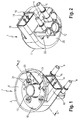
- FIG. 1 shows a three-dimensional plan view of an embodiment of a heater 1 according to the invention for a fuel filter. This is placed in a filter housing into which the heater described in more detail below is integrated. Such filters are known from the prior art, so that relevant explanations can be omitted.
- the heating device 1 has an approximately pot-shaped housing 2, on which an inlet 4 and an outlet 6 are arranged.
- the diesel fuel to be heated enters through the inlet 4 into the housing interior 8 and is then heated by a heater 10 received in the housing 8 and then flows through the filter element. After filtration, the diesel fuel flows axially through a central port 12 and the outlet 6 from the filter.
- FIG. 2 shows a view from below of the housing 2. It can be seen approximately cup-shaped structure of the housing 2 with the socket 18, which extends approximately tangentially from a housing bottom 20 out.
- the executed for mounting a hose line outlet 6 opens approximately tangentially in the over the housing bottom 20 also extended downwardly projecting central nozzle 12, which is closed at the bottom.
- the inlet 4 opens into a likewise from the housing bottom 20 down (view FIG. 2 ) extending inlet port 22, which in turn opens in the region of the housing interior 8, in which the heater 10 is arranged.
- the housing 2 is designed as an injection molded plastic.
- the heater 10 has approximately a circular ring segment structure, which surrounds the central socket 12 at least in sections.
- the housing interior 8 is partially subdivided by a partition wall 24, wherein the heater 10 is arranged in the larger circular segment-like housing part.
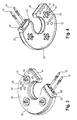
- FIGS. 3 and 4 show a detail of the heater 10.
- the partitioned in the partition 24 interior 8 of the housing 2 used heater 10 has an approximately omega-shaped structure with a mounting bracket 26, in which the actual heating with two contact plates 28, 30 and more, in the present case three disk-shaped heating elements, such as PTC resistor elements 32 (see FIG. 5 ) are included.
- the mounting bracket 26 is open at the bottom, so that the inlet-side contact plate 30 is visible.
- the fixing elements 34 explained in more detail below are supported with an end section in spring sleeves 36, which extend out of a bottom 38 of the mounting bracket 26.
- the three fixing elements 34 respectively pass through the two contact plates 28, 30 and one of the heating elements 32 such that in FIG. 4 visible connecting portions 40 protrude from the mounting bracket 26. These connection sections are then based on FIG. 6 closer explained recordings 41 in the housing bottom 20 pressed. Accordingly, the heater 10 with the mounting bracket 26, the two contact plates 28, 30 and the heating elements 32 relative to each other fixed in position and clamped on the fixing elements 34 and beyond this preassembled heating package in the housing 2.
- the bracing of the heater pact takes place via spring elements 42 which are each supported on a radial collar 44 of a fixing element 34 and at the in FIG. 4 visible large area of the contact plate 30 attack.
- the omega-shaped mounting bracket 26 has two end faces 46, 48, wherein the end face 46 abuts against the partition wall 24 and in the end face 48, the two contact pins 14, 16 are contacted via a contact housing 50 with one of the contact plates 28, 30.
- the diesel fuel flows through the inlet 4 in the bottom area in the housing interior 8 and enters via recesses 52 of the contact plate 30 in the limited of the two contact plates 28, 30 first heating chamber.
- the over the heating elements 32 and the two contact plates 28, 30 heated diesel fuel then flows over in the "upper" contact plate 28 formed outlet openings 54 in the space between the contact plate 28 and the bottom 38 of the mounting bracket 26.
- the diesel fuel then flows through this second heating chamber at the bottom of the contact plate 28 enlang and is further heated.
- the fuel flows via corresponding openings 56 in the bottom 38 of the mounting bracket 26 from the heater 10 towards the filter element and is then removed after filtration through the above-mentioned central nozzle 12 and the outlet 6.
- FIG. 5 shows an exploded view of the heater 10, wherein these in comparison to the representation in FIG. 1 rotated by 180 °. It can be seen then upwardly open mounting bracket 26 with an omega-shaped peripheral wall 58 which surrounds the bottom 38.
- the contact plate 28 has three mounting recesses 64, which lie on the same pitch circle diameter as the Zentriersockel 60 and which are interspersed in the mounting position of each of the Zentriersockel 60.
- the further contact plate 30 has three lying on a corresponding pitch mounting recesses 66 which are interspersed in the assembled state of the Zentriersockeln 60.
- the three heating elements 32 are each provided with a central opening 67, so that the Zentriersockel 60 and the heating elements 32 prevail.
- a contact eye 68, 70 is formed in each case by punch bending, which is contacted with the corresponding contact pin 14, 16, so that at Connection to the electrical system and appropriate control the heating elements 32 energized or switched off electricity.
- step-shaped circumferential supports 72, 74 are formed, on which rests the contact plate 28 and the contact plate 30 with its peripheral portions. As shown in the illustration FIG. 5 can be removed, the peripheral wall 58 is narrowed stepwise through the peripheral supports 72, 74 to the bottom 38, so that corresponding to the bottom-side contact plate 28 has a slightly smaller diameter than the in FIG. 5 having overhead contact plate 30.
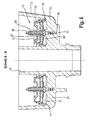
- FIG. 6 shows a section along the line AA in FIG. 1 ,
- the mounting bracket 26 covers the package of the two contact plates 28, 30 and the intermediate heating elements 32. He lies with a front edge 77 like a bell on a shoulder of the housing 2, so that between the housing bottom 20 and the contact plate 30, an inlet space 75 is limited, in which the diesel fuel flows.
- the connecting portion 40 of the fixing 34 is, as explained above, in receptacles 41 of the housing bottom 20 is pressed so that the heater 10, which can be supplied as a preassembled unit, is reliably connected to the housing 2.
- the central port 12 which is encompassed by the heater 10 and extending through the housing bottom 20 therethrough.
- FIG. 7 shows that 40 two sharp-edged, fir-tree-like radial projections 76 are formed on the outer circumference of the pin-shaped connecting portion 40, which dig into the peripheral wall of the receptacle 42 during insertion of this connecting portion 40 and thus ensure a positive and positive connection of the heater 10 with the housing bottom 20.
- a support collar 78 which forms a support surface 80 on which the radial collar 44 of the pin-shaped fixing element 34 rests.
- the spring element 42 is of the in FIG.
- the centering socket 60 protrudes downward from a bead 82 of the mounting bracket 26 and passes through the mounting recesses 64 and 66 of the contact plates 28 and 30 and the opening 67 of the heating element 32 so that they are centered.
- the spring sleeve 36 described above is formed, which is penetrated by the overhead end portion of the fixing element 34.
- the spring sleeve 36 has three spring tabs 88, of which in FIG. 7 only two are visible. These spring tabs 88 surround together with the coaxial with the spring sleeve 36 formed Zentriersockel 60 a portion of the fixing element 34.
- the inner diameter of the Zentriersockels 60 and the spring tabs 88 is significantly larger than the outer diameter of a pin portion 90 of the fixing 34, so that a game S results with which the pin portion 90 is displaceable in the radial direction within the space encompassed by the elastic spring tabs 88 and the centering base 60.
- the pin portion 90 may be provided with a constriction 94.
- the pin portion 90 extends extending through the spring sleeve 36 and has at its end a mushroom-shaped extension 96, which forms a contact shoulder 98 which rests on an end face 100 of the spring sleeve 36.
- the diameter of the extension corresponds approximately to the clear width of the spring sleeve 36, so that the pin portion 90 from below ( Fig. 7 ) can be inserted into the spring sleeve.
- the Zentriersockel 60 and the adjoining spring sleeve 36 thus extends in the area between the abutment shoulder 98 of the extension 96 and another abutment shoulder 102 which is formed by the annular end face of the axial projection 86 of the radial collar 44 - the fixing element 34 is thus mounted without play in the axial direction - In the radial direction, the fixing member 34 can be moved due to the spring action of the spring tabs 88 and the game S.
- This game makes it possible to compensate for any manufacturing tolerances in the formation of the receptacles 41 in the housing base 20, so that the housing 2 can be manufactured with relatively large tolerances and thus very inexpensive, without any reworking is required.
- the contact plates 28, 30 may be made of, for example, tin bronze, an aluminum alloy, or a similar conductive material.
- the housing 2 and the mounting bracket 26 are designed as injection molded parts.
- the fixing element 34 is preferably made of stainless steel or the like.
- the spring elements 42 are made of a suitable spring steel, which allows a sufficient bias even at the temperatures occurring.
- the spring elements 42 When installing the above-described heater after insertion of the two contact plates 28, 30 and the PTC heating elements 32 in the mounting bracket 26, the spring elements 42 must be positioned and mounted together with the fixing elements 34. It may happen that in a malposition in which the annular end face 84 of the fixing element 34 is not exactly axially through an opening 43 (please refer FIG. 7 ) of the spring element 42 dives, the unit is not easy to install.
- FIG. 8 shows a variant in which this mispositioning and the associated difficulties in mounting are eliminated.
- the centering base 60 in the axial direction is slightly wider than in the previously described embodiment via the lower contact plate 30 (FIG. FIG. 8 ) and lies with its annular end face 84 directly on the spring element 42 and not - as in the embodiment described above - on the contact shoulder 102 of an axial projection of the radial collar 44.
- This in accordance with the embodiment FIG. 7 existing axial projection 86 is in the variant according to FIG. 8 omitted, although the diameter d of the opening 43 is formed significantly smaller than the outer diameter of the annular end face 84, so that it rests on the spring element 42 correspondingly flat.
- the outer diameter t of the pin portion 90 is significantly smaller than the inner diameter of the spring sleeve 36 and thus also smaller than the diameter d of the opening 34 of the spring member 42 executed so that its radial clearance with respect to the pin portion 90 is greater than the above-described game S is. In this way, it is not necessarily required to align the annular end face 84 axially to the opening 43 exactly, so that the assembly is significantly simplified.
- a heating device for heating a gaseous or liquid medium, for example diesel fuel, in which a heater with two contact plates and at least one heating element are pre-mounted via a fixing element and fastened via this fixing element in or on a housing.
Abstract
Description
Die Erfindung betrifft eine Heizeinrichtung gemäß dem Oberbegriff des Patentanspruches 1.The invention relates to a heating device according to the preamble of
Derartige Heizeinrichtungen werden beispielsweise bei Dieselmotoren mit einem Filter kombiniert, so dass der Dieselkraftstoff beim Kaltstart schnellstmöglich auf Betriebstemperatur gebracht werden kann.Such heaters are combined, for example, in diesel engines with a filter, so that the diesel fuel can be brought to operating temperature as soon as possible during cold start.
In der
Die Befestigung der sandwichartigen Konstruktion aus Kontaktplatten und dazwischen liegenden scheibenförmigen Heizelementen erfolgt bei der bekannten Lösung durch eine Vielzahl von an einem Gehäuseboden abgestützten Haltestiften, die die beiden koaxial angeordneten Kontaktplatten durchsetzen, wobei die oben liegende, von dem Gehäuseboden entfernte Kontaktplatte mit Klemmzungen ausgeführt ist, die es ermöglichen, diese Kontaktplatte an den Haltestiften festzuklemmen und somit das Paket mit einer vorbestimmten Vorspannung thermisch und elektrisch zu kontaktieren. In der
Die
In der
All die vorbeschriebenen Lösungen haben den Nachteil gemeinsam, dass die einzelnen Bauelemente der Heizeinrichtung, beispielsweise das Gehäuse und die beiden Kontaktbleche mit hinreichender Präzision gefertigt werden müssen, da die exakte Relativpositionierung zu den oben erläuterten Fixierelementen eingehalten werden muss, um eine hinreichende Kontaktierung zu gewährleisten. Darüber hinaus ist auch die Montage der Heizeinrichtung aufwendig, da in auf einander folgenden Schritten zunächst das bodenseitige Kontaktblech in das Gehäuse eingesetzt und dann darauf die Heizelemente und das oben liegende Kontaktblech und ggf. ein Federelement positioniert werden müssen.All the solutions described above have the common disadvantage that the individual components of the heater, such as the housing and the two contact plates must be made with sufficient precision, since the exact relative positioning has to be adhered to the above-described fixing elements to ensure adequate contact. In addition, the assembly of the heating device is complicated, since in successive steps, first the bottom-side contact plate inserted into the housing and then the heating elements and the overhead contact plate and possibly a spring element must be positioned on it.
Demgegenüber liegt der Erfindung die Aufgabe zugrunde, eine Heizeinrichtung zu schaffen, die auf einfache Weise montierbar und herstellbar ist.In contrast, the invention has for its object to provide a heater that is easy to install and produce.
Diese Aufgabe wird durch eine Heizeinrichtung mit den Merkmalen des Patentanspruches 1 gelöst.This object is achieved by a heating device with the features of
Vorteilhafte Weiterbildungen der Erfindung sind Gegenstand der Unteransprüche.Advantageous developments of the invention are the subject of the dependent claims.
Erfindungsgemäß hat die Heizeinrichtung ein Gehäuse, an dem ein Einlass und ein Auslass für ein zu erwärmendes gasförmiges oder flüssiges Medium ausgebildet sind. In diesem Gehäuse ist eine Heizung aufgenommen, die eine erste und eine zweite Kontaktplatte hat, zwischen denen etwa scheibenförmige Heizelemente angeordnet sind. Diese Heizung ist mittels zumindest eines Fixierelementes an dem Gehäuse festgelegt, wobei dieses Fixierelement oder die Fixiereinrichtung abschnittsweise die Kontaktplatten durchsetzt. Erfindungsgemäß ist dieses Fixierelement mit einer ersten und einer zweiten Anlageschulter ausgeführt, zwischen denen die Kontaktplatten und die Heizelemente lagefixierbar sind. Das Fixierelement hat des Weiteren einen Verbindungsabschnitt, der sich über das Paket aus Kontaktplatten und Heizelementen hinaus erstreckt und in eine Aufnahme des Gehäuses eingesetzt ist.According to the invention, the heating device has a housing, on which an inlet and an outlet for a gaseous or liquid medium to be heated are formed. In this housing, a heater is accommodated, which has a first and a second contact plate, between which approximately disk-shaped heating elements are arranged. This heater is fixed by means of at least one fixing element on the housing, said fixing or the fixing device partially passes through the contact plates. According to the invention, this fixing element is designed with a first and a second abutment shoulder, between which the contact plates and the heating elements can be fixed in position. The fixing member further has a connecting portion which extends beyond the package of contact plates and heating elements and is inserted into a receptacle of the housing.
Erfindungsgemäß wird somit eine Lösung vorgeschlagen, bei der das Paket, bestehend aus dem Montageträger, den Kontaktplatten und den dazwischen angeordneten Heizelementen an dem Fixierelement lagefixierbar ist und somit vormontiert werden kann. Diese vormontierte Einheit kann dann ohne größeren Aufwand in das Gehäuse eingesetzt werden, wobei zur Befestigung am Gehäuse wiederum das Fixierelement verwendet wird. Dieses erfüllt somit eine Doppelfunktion, da es zum einen die Heizung am Gehäuse hält und zum anderen die Bauelemente der Heizung, zumindest dessen Kontaktplatten und die dazwischen liegenden Heizelemente zueinander lagefixiert. Dies ermöglicht es, die Heizung als vormontierte Einheit zwischenzulagern und bei Bedarf einzubauen, so dass die Fertigung wesentlich vereinfacht wird.According to the invention, a solution is thus proposed in which the package, consisting of the assembly carrier, the contact plates and the heating elements arranged therebetween, is fixable in position on the fixing element and thus can be preassembled. This preassembled unit can then be used without much effort in the housing, in turn, for fixing to the housing, the fixing element is used. This thus fulfills a dual function, since on the one hand holds the heater on the housing and on the other hand, the components of the heater, at least its contact plates and the intermediate heating elements fixed in position to each other. This makes it possible to temporarily store the heater as a preassembled unit and install it if necessary, so that the production is much easier.
Bei einem Ausführungsbeispiel der Erfindung ist das Paket in einem Montageträger aufgenommen, an dem zumindest eine sich vom Paket weg erstreckende Federhülse ausgebildet ist, durch die hindurch sich das Fixierelement mit der ersten Anlageschulter erstreckt, so dass diese an einer Stirnfläche der Federhülse abgestützt ist.In one embodiment of the invention, the package is received in a mounting bracket on which at least one spring sleeve extending away from the package is formed, through which the fixing element extends with the first abutment shoulder, so that it is supported on an end face of the spring sleeve.
Mit dieser Variante kann das Fixierelement bereits am Montageträger vormontiert werden, da es mittels der Federhülse gehalten wird.With this variant, the fixing can already be pre-assembled on the mounting bracket, since it is held by means of the spring sleeve.
Die Montage der Heizung ist vereinfacht, wenn das Paket mit den Kontaktplatten und den oder dem Heizelement in einen Montageträger aufgenommen ist, in dem das Paket mit seitlichem Spiel zum Toleranzausgleich mit Bezug zur Aufnahme des Gehäuses festlegbar ist. D.h. der Montageträger ist so ausgeführt, dass das Paket Toleranzen, die bei der Fertigung des Gehäuses auftreten können, ausgleichen kann. Auf diese Weise ist es möglich, das Gehäuse mit vergleichsweise großer Maßtoleranz auszuführen, ohne die Maßhaltigkeit der Gesamtanordnung negativ zu beeinflussen.The installation of the heater is simplified when the package is received with the contact plates and the or the heating element in a mounting bracket in which the package with lateral clearance for tolerance compensation with respect to the housing of the housing can be fixed. Ie the mounting bracket is designed so that the package tolerances that can occur in the manufacture of the housing can compensate. In this way, it is possible to carry out the housing with a comparatively large dimensional tolerance, without negatively influencing the dimensional accuracy of the overall arrangement.
Eine Variante der Heizeinrichtung sieht es vor, eine Federhülse mit einer Vielzahl von Federlaschen auszuführen, die gemeinsam einen Aufnahmeraum für einen Teilbereich des Fixierelementes bilden.A variant of the heating device provides for a spring sleeve having a plurality of spring tabs to be formed, which together form a receiving space for a partial area of the fixing element.
Ein Toleranzausgleich ist besonders einfach, wenn die lichte Weite des durch die Federlaschen gebildeten Aufnahmeraumes deutlich größer als der Durchmesser des Fixierelementes ausgebildet ist. Dies ermöglicht es, das Fixierelement in die Aufnahme des Gehäuses einzusetzen und den Toleranzausgleich durch das radiale Spiel im Montageträger auszugleichen. Selbstverständlich ist dieses radiale Spiel so ausgelegt, dass die Relativpositionierung der Heizung mit den Kontaktblechen und den dazwischen liegenden Heizelementen in der gewünschten Weise erfolgen kann.A tolerance compensation is particularly simple if the clear width of the receiving space formed by the spring tabs is formed significantly larger than the diameter of the fixing. This makes it possible to use the fixing in the receptacle of the housing and compensate for the tolerance compensation by the radial clearance in the mounting bracket. Of course, this radial clearance is designed so that the relative positioning of the heater can be done with the contact plates and the intermediate heating elements in the desired manner.
Eine Weiterbildung der Erfindung sieht es vor, Federlaschen einer Federhülse zum Fixierelement hin einzuziehen, so dass sie am Außenumfang des Fixierelementes anliegen.A further development of the invention provides for retracting spring tabs of a spring sleeve towards the fixing element, so that they bear against the outer circumference of the fixing element.
Bei einem bevorzugten Ausführungsbeispiel der Erfindung ist das Fixierelement stiftartig ausgeführt, wobei an einem Endabschnitt die erste Anlageschulter durch eine Erweiterung ausgebildet ist, welche beispielsweise pilzförmig ausgeformt sein kann. Deren Durchmesser ist so gewählt, dass sie durch die Federhülse hindurch eingesetzt werden kann. Im Axialabstand zu dieser Anlageschulter ist ein Radialbund vorgesehen, der die zweite Anlageschulter ausbildet. An dem anderen Endabschnitt des stiftartigen Fixierelements ist der Verbindungsabschnitt zum Einsetzen in die gehäuseseitige Aufnahme ausgeführt.In a preferred embodiment of the invention, the fixing element is designed like a pin, wherein at one end portion, the first abutment shoulder is formed by an extension, which may be formed, for example mushroom-shaped. Its diameter is chosen so that it can be inserted through the spring sleeve. At the axial distance to this abutment shoulder a radial collar is provided, which forms the second abutment shoulder. At the other end portion of the pin-like fixing member, the connecting portion for insertion into the housing-side receptacle is executed.
Bei einem Ausführungsbeispiel der Erfindung erfolgt eine Zentrierung des Federelementes mittels eines radial zurückgesetzten Axialvorsprungs des Radialbunds, wobei das Federelement mit einer Ausnehmung den Axialvorsprung umgreift und somit zentriert ist. Bei einer vereinfachten Ausführungsform entfällt dieser Axialvorsprung, so dass das Federelement axial auf dem Radialvorsprung aufliegt und in Radialrichtung etwas verschiebbar ist. Diese Ausführungsform lässt sich deutlich einfacher montieren, da der Axialvorsprung nicht mehr mit Bezug zum Federelement ausgerichtet werden muss.In one embodiment of the invention, a centering of the spring element takes place by means of a radially recessed axial projection of the radial collar, wherein the spring element engages around the axial projection with a recess and thus is centered. In a simplified embodiment, this axial projection is eliminated, so that the spring element rests axially on the radial projection and slightly displaceable in the radial direction. This embodiment is much easier to assemble, since the axial projection no longer needs to be aligned with respect to the spring element.
Die Anmeldering behält sich vor, auf die mit Radialspiel ausgeführte Abstützung des Federelementes einen eigenen abhängigen oder unabhängigen Anspruch zu richten.The applicant reserves the right to make its own dependent or independent claim to the supported with radial play support of the spring element.
Die Montage ist weiter vereinfacht, wenn der Verbindungsabschnitt des Fixierelementes kraft- und/oder formschlüssig in die Aufnahme eingesetzt wird. Hierzu können beispielsweise am Verbindungsabschnitt ein oder mehrere Radialvorsprünge ausgeführt werden, die eine Art Verzahnung bilden, die reib- und stoffschlüssig in die Aufnahme eingepresst wird.The assembly is further simplified if the connecting portion of the fixing element is non-positively and / or positively inserted into the receptacle. For this purpose, for example, one or more radial projections can be made on the connecting portion, which form a kind of toothing, which is pressed into the receptacle in a frictional and cohesive manner.
Zur besseren Relativpositionierung der Heizung können an Innenumfangswandungen des Montageträgers umlaufende Auflagen für Umfangsabschnitte der Kontaktplatten ausgeführt sein, so dass diese umlaufend im Montageträger abgestützt sind.For better relative positioning of the heating circumferential supports for peripheral portions of the contact plates can be executed on Innenumfangswandungen of the mounting bracket, so that they are circumferentially supported in the mounting bracket.
Diese Auflagen können zur Verbesserung der Abdichtung so ausgeführt sein, dass die Anlage im Wesentlichen linienförmig erfolgen - auf diese Weise wird ein hohe "Linienpressung" beim Verspannen des Paketes erzielt, so dass die Umfangsbereiche nach außen hin abgedichtet sind.These pads can be designed to improve the seal so that the system is essentially linear - in this way a high "line pressure" is achieved when clamping the package, so that the peripheral areas are sealed to the outside.
Ein Ausführungsbeispiel der Erfindung sieht vor, die zum Verbindungsabschnitt der Fixierelemente benachbarte Kontaktplatte mit einem größeren Durchmesser als die andere Kontaktplatte auszuführen, wobei die Abstützung im Montageträger entsprechend erfolgt.An embodiment of the invention provides to perform the connecting portion of the fixing elements adjacent contact plate with a larger diameter than the other contact plate, wherein the support in the mounting bracket is done accordingly.
Erfindungsgemäß wird es bevorzugt, wenn die zweite Anlageschulter des Fixierelementes durch einen Radialbund gebildet ist, der an einer entsprechenden Stützfläche des Gehäuses abgestützt ist.According to the invention, it is preferred if the second abutment shoulder of the fixing element is formed by a radial collar which is supported on a corresponding support surface of the housing.
Gemäß einer Weiterbildung der Erfindung ist das Paket über zumindest ein Federelement zwischen den Anlageschultern des Fixierelementes verspannt.According to one embodiment of the invention, the package is clamped over at least one spring element between the abutment shoulders of the fixing.
Bei einem bevorzugten Ausführungsbeispiel sind auch die Heizelemente von jeweils einem Fixierelement durchsetzt.In a preferred embodiment, the heating elements are penetrated by a respective fixing.
Wie bereits erläutert, ist das Heizelement vorzugsweise als PTC-Widerstandselement ausgeführt.As already explained, the heating element is preferably designed as a PTC resistance element.
Bevorzugte Ausführungsbeispiele der Erfindung werden im Folgenden anhand schematischer Zeichnungen näher erläutert. Es zeigen:
-
Figur 1 -
Figur 2Figur 1 -
Figur 3 eine Einzeldarstellung einer Heizung der Heizeinrichtung gemäßFigur 1 -
Figur 4 eine Unteransicht der Heizung gemäßFigur 3 ; -
Figur 5 eine Explosionsdarstellung der Heizung gemäßFigur 3 ; -
Figur 6Figur 1 -
Figur 7 einen Teilbereich derFigur 6 -
Figur 8 ein weiteres Ausführungsbeispiel einer Heizeinrichtung.
-
FIG. 1 a plan view of a heater according to the invention, which is attached to a diesel filter; -
FIG. 2 a bottom view of the heater offFIG. 1 ; -
FIG. 3 a detailed representation of a heater of the heater according toFIG. 1 ; -
FIG. 4 a bottom view of the heater according toFIG. 3 ; -
FIG. 5 an exploded view of the heater according toFIG. 3 ; -
FIG. 6 a longitudinal section along the line AA inFIG. 1 ; -
FIG. 7 a subsection of theFIG. 6 in an enlarged view and -
FIG. 8 another embodiment of a heater.
Die Heizeinrichtung 1 hat ein etwa topfförmiges Gehäuse 2, an dem ein Einlass 4 und ein Auslass 6 angeordnet sind. Der zu erwärmende Dieselkraftstoff tritt durch den Einlass 4 in den Gehäuseinnenraum 8 ein und wird dann über eine im Gehäuse 8 aufgenommene Heizung 10 erwärmt und durchströmt anschließend das Filterelement. Nach der Filtrierung strömt der Dieselkraftstoff axial über einen Zentralstutzen 12 und den Auslass 6 aus dem Filter ab.The
Die elektrische Kontaktierung der Heizung 10 erfolgt über zwei Kontaktstifte 14, 16, die aus einer Fassung 18 für einen Stecker zur Verbindung mit dem Bordnetz etwa tangential auskragen.The electrical contacting of the
Der Einlass 4 mündet in einen sich ebenfalls aus dem Gehäuseboden 20 nach unten (Ansicht nach
Gemäß der Draufsicht in
Der Gehäuseinnenraum 8 ist dabei abschnittsweise von einer Trennwandung 24 unterteilt, wobei die Heizung 10 in dem größeren kreissegmentartigen Gehäuseteil angeordnet ist.The housing interior 8 is partially subdivided by a
Die
Wie besonders gut anhand der
Der Dieselkraftstoff strömt durch den Einlass 4 im Bodenbereich in das Gehäuseinnere 8 ein und tritt über Ausnehmungen 52 der Kontaktplatte 30 in den von den beiden Kontaktplatten 28, 30 begrenzten ersten Heizraum ein. Der über die Heizelemente 32 und die beiden Kontaktplatten 28, 30 erwärmte Dieselkraftstoff strömt dann über in der "oberen" Kontaktplatte 28 ausgebildete Auslassöffnungen 54 in den Raum zwischen der Kontaktplatte 28 und den Boden 38 des Montageträgers 26. Der Dieselkraftstoff strömt dann durch diesen zweiten Heizraum an der Unterseite der Kontaktplatte 28 enlang und wird weiter erwärmt. Dann fließt der Kraftstoff über entsprechende Durchbrüche 56 im Boden 38 des Montageträgers 26 aus der Heizung 10 ab hin zum Filterelement und wird dann nach der Filtrierung durch den oben angesprochenen Zentralstutzen 12 und den Auslass 6 abgeführt.The diesel fuel flows through the inlet 4 in the bottom area in the housing interior 8 and enters via
Weitere Einzelheiten der Heizung 10 werden anhand
Aus dem Boden 38 stehen nach oben hin (Ansicht nach
Im Bereich um die Zentriersockel 60 ist am Boden 38 noch eine Vielzahl von etwa radial dazu angeordneten Stützstegen 62 vorgesehen. Die Kontaktplatte 28 hat drei Montageausnehmungen 64, die auf dem gleichen Teilkreisdurchmesser wie die Zentriersockel 60 liegen und die in der Montageposition jeweils von einem der Zentriersockel 60 durchsetzt sind. In entsprechender Weise hat auch die weitere Kontaktplatte 30 drei auf einem entsprechenden Teilkreis liegende Montageausnehmungen 66, die im montierten Zustand von den Zentriersockeln 60 durchsetzt sind. Die drei Heizelemente 32 sind jeweils mit einem mittigen Durchbruch 67 versehen, so dass die Zentriersockel 60 auch die Heizelemente 32 durchsetzen.In the area around the centering
An den beiden in
An der Umfangswandung 58 des Montageträgers 26 sind stufenförmig umlaufende Auflagen 72, 74 ausgebildet, auf denen die Kontaktplatte 28 bzw. die Kontaktplatte 30 mit ihren Umfangsabschnitten aufliegt. Wie der Darstellung gemäß
Wie sich insbesondere aus der vergrößerten Detaildarstellung gemäß
Gemäß der vergrößerten Darstellung in
Wie insbesondere aus der Darstellung in
Die in
Durch die in Axialrichtung spielfreie Aufnahme des Fixierelementes 34 im Montageträger 26 ist auch stets eine hinreichende Vorspannung und Kontaktierung der Bauelemente des Heizers, d.h. im Wesentlichen der Kontaktplatten 28, 30 und der dazwischen liegenden Heizelemente 32 gewährleistet.Due to the axially play-free recording of the fixing
Beim beschriebenen Ausführungsbeispiel können die Kontaktplatten 28, 30 beispielsweise aus Zinnbronze, einer Aluminiumlegierung oder einem ähnlichen leitenden Material hergestellt sein. Das Gehäuse 2 und der Montageträger 26 sind als Spritzgussteile ausgeführt. Das Fixierelement 34 wird vorzugsweise aus Edelstahl oder dergleichen ausgebildet. Die Federelemente 42 bestehen aus einem geeigneten Federstahl, der auch bei den auftretenden Temperaturen eine hinreichende Vorspannung ermöglicht.In the described embodiment, the
Bei der Montage der vorbeschriebenen Heizeinrichtung müssen nach dem Einsetzen der beiden Kontaktplatten 28, 30 und der PTC-Heizelemente 32 in den Montageträger 26 die Federelemente 42 zusammen mit den Fixierelementen 34 positioniert und montiert werden. Dabei kann es vorkommen, dass es bei einer Fehlstellung, in der die Ringstirnfläche 84 des Fixierelementes 34 nicht exakt axial durch einen Durchbruch 43 (siehe
Offenbart ist eine Heizeinrichtung zur Erwärmung eines gasförmigen oder flüssigen Mediums, beispielsweise Dieselkraftstoff, bei dem eine Heizung mit zwei Kontaktplatten und zumindest einem Heizelement über ein Fixierelement vormontiert und über dieses Fixierelement in oder an einem Gehäuse befestigt sind.Disclosed is a heating device for heating a gaseous or liquid medium, for example diesel fuel, in which a heater with two contact plates and at least one heating element are pre-mounted via a fixing element and fastened via this fixing element in or on a housing.
- 11
- Heizeinrichtungheater
- 22
- Gehäusecasing
- 44
- Einlassinlet
- 66
- Auslassoutlet
- 88th
- GehäuseinnenraumHousing interior
- 1010
- Heizungheater
- 1212
- ZentralstutzenCentral neck
- 1414
- Kontaktstiftpin
- 1616
- Kontaktstiftpin
- 1818
- Fassungversion
- 2020
- Gehäusebodencaseback
- 2222
- Einlassstutzeninlet port
- 2424
- Trennwandungpartition wall
- 2626
- Montageträgermounting bracket
- 2828
- Kontaktplattecontact plate
- 3030
- Kontaktplattecontact plate
- 3232
- Heizelementheating element
- 3434
- Fixierelementfixing
- 3636
- Federhülsespring sleeve
- 3838
- Bodenground
- 4040
- Verbindungsabschnittconnecting portion
- 4141
- Aufnahmeadmission
- 4242
- Federelementspring element
- 4343
- Durchbruchbreakthrough
- 4444
- Radialbundradial collar
- 4646
- Stirnflächeface
- 4848
- Stirnflächeface
- 5050
- KontaktgehäuseContact housing
- 5252
- Ausnehmungrecess
- 5454
- Auslassöffnungoutlet
- 5656
- Durchbruchbreakthrough
- 5858
- Umfangswandungperipheral
- 6060
- Zentriersockelcentering socket
- 6262
- Stützstegsupporting web
- 6464
- Montageausnehmungmounting recess
- 6666
- Montageausnehmungmounting recess
- 6767
- Durchbruchbreakthrough
- 6868
- Kontaktöseeyelet
- 7070
- Kontaktöseeyelet
- 7272
- Auflageedition
- 7474
- Auflageedition
- 7575
- Einlassrauminlet space
- 7676
- Radialvorsprungradial projection
- 7777
- Stirnkantefront edge
- 7878
- Stützbundsupporting collar
- 8080
- Stützflächesupport surface
- 8282
- SickeBeading
- 8484
- RingstirnflächeAnnular face
- 8686
- Axialvorsprungaxial projection
- 8888
- Federlaschespring shackle
- 9090
- PinabschnittPinabschnitt
- 9292
- InnenumfangskanteInner peripheral edge
- 9494
- Einschnürungconstriction
- 9696
- Erweiterungextension
- 9898
- Anlageschultercontact shoulder
- 100100
- Stirnflächeface
- 102102
- Anlageschultercontact shoulder
Claims (15)
Applications Claiming Priority (2)
| Application Number | Priority Date | Filing Date | Title |
|---|---|---|---|
| DE102010060835 | 2010-11-26 | ||
| DE102011000246A DE102011000246A1 (en) | 2010-11-26 | 2011-01-20 | heater |
Publications (1)
| Publication Number | Publication Date |
|---|---|
| EP2458191A1 true EP2458191A1 (en) | 2012-05-30 |
Family
ID=45063023
Family Applications (1)
| Application Number | Title | Priority Date | Filing Date |
|---|---|---|---|
| EP11190576A Withdrawn EP2458191A1 (en) | 2010-11-26 | 2011-11-24 | Heating device |
Country Status (2)
| Country | Link |
|---|---|
| EP (1) | EP2458191A1 (en) |
| DE (1) | DE102011000246A1 (en) |
Cited By (1)
| Publication number | Priority date | Publication date | Assignee | Title |
|---|---|---|---|---|
| DE102015220968A1 (en) * | 2015-10-27 | 2017-04-27 | Mahle International Gmbh | Preheating device for preheating fuel |
Families Citing this family (2)
| Publication number | Priority date | Publication date | Assignee | Title |
|---|---|---|---|---|
| DE102013213024A1 (en) * | 2013-07-03 | 2015-01-08 | Mahle International Gmbh | heater |
| DE102013013713A1 (en) | 2013-08-20 | 2015-02-26 | Mann + Hummel Gmbh | Fluid system with at least one heater for fluid and heater |
Citations (7)
| Publication number | Priority date | Publication date | Assignee | Title |
|---|---|---|---|---|
| EP0162939A1 (en) * | 1984-05-29 | 1985-12-04 | David + Baader DBK Spezialfabrik Elektrischer Apparate und Heizwiderstände GmbH | Fuel heater for a diesel engine |
| EP0657199A2 (en) | 1993-12-13 | 1995-06-14 | Stanadyne Automotive Corp. | Heater module for filter assembly |
| EP1158158A1 (en) | 2000-05-25 | 2001-11-28 | David + Baader DBK GmbH | PTC heating device |
| EP1510686A1 (en) * | 2003-09-01 | 2005-03-02 | David & Baader DBK Spezialfabrik elektrischer Apparate und Heizwiderstände GmbH | Heating device for a medium to be heated |
| EP1510688B1 (en) | 2003-09-01 | 2008-03-26 | DBK David + Baader GmbH | Heating device for a medium to be heated |
| EP1510685B1 (en) | 2003-09-01 | 2008-03-26 | DBK David + Baader GmbH | Heating device for a medium to be heated |
| WO2012011879A1 (en) * | 2010-07-22 | 2012-01-26 | Hidria Aet Družba Za Proi̇zvodnjo Vžignih Sistemov In Elektronike D.O.O. | Diesel fuel heater for road vehicles |
Family Cites Families (2)
| Publication number | Priority date | Publication date | Assignee | Title |
|---|---|---|---|---|
| US4406785A (en) * | 1981-12-24 | 1983-09-27 | Gte Products Corporation | Diesel fuel heater |
| IT1233595B (en) * | 1989-05-30 | 1992-04-06 | Gilardini Spa | FILTER FOR DIESEL EQUIPPED WITH SELF-REGULATING HEATING MEDIUM |
-
2011
- 2011-01-20 DE DE102011000246A patent/DE102011000246A1/en not_active Withdrawn
- 2011-11-24 EP EP11190576A patent/EP2458191A1/en not_active Withdrawn
Patent Citations (7)
| Publication number | Priority date | Publication date | Assignee | Title |
|---|---|---|---|---|
| EP0162939A1 (en) * | 1984-05-29 | 1985-12-04 | David + Baader DBK Spezialfabrik Elektrischer Apparate und Heizwiderstände GmbH | Fuel heater for a diesel engine |
| EP0657199A2 (en) | 1993-12-13 | 1995-06-14 | Stanadyne Automotive Corp. | Heater module for filter assembly |
| EP1158158A1 (en) | 2000-05-25 | 2001-11-28 | David + Baader DBK GmbH | PTC heating device |
| EP1510686A1 (en) * | 2003-09-01 | 2005-03-02 | David & Baader DBK Spezialfabrik elektrischer Apparate und Heizwiderstände GmbH | Heating device for a medium to be heated |
| EP1510688B1 (en) | 2003-09-01 | 2008-03-26 | DBK David + Baader GmbH | Heating device for a medium to be heated |
| EP1510685B1 (en) | 2003-09-01 | 2008-03-26 | DBK David + Baader GmbH | Heating device for a medium to be heated |
| WO2012011879A1 (en) * | 2010-07-22 | 2012-01-26 | Hidria Aet Družba Za Proi̇zvodnjo Vžignih Sistemov In Elektronike D.O.O. | Diesel fuel heater for road vehicles |
Cited By (1)
| Publication number | Priority date | Publication date | Assignee | Title |
|---|---|---|---|---|
| DE102015220968A1 (en) * | 2015-10-27 | 2017-04-27 | Mahle International Gmbh | Preheating device for preheating fuel |
Also Published As
| Publication number | Publication date |
|---|---|
| DE102011000246A1 (en) | 2012-05-31 |
Similar Documents
| Publication | Publication Date | Title |
|---|---|---|
| EP1917088B1 (en) | Filter device comprising a heater | |
| DE102007005771B4 (en) | Filter device, in particular liquid filter, with a heater | |
| DE4233913C2 (en) | Electrically heated thermostatic valve for a coolant circuit of an internal combustion engine | |
| EP2637475B1 (en) | Heat generating element | |
| EP2608632A1 (en) | Electrical heating device and frame for same | |
| EP2637474A1 (en) | Heat generating element | |
| EP1235128A2 (en) | Means for applying an actuator or a thermostat head on a valve | |
| DE102011056144B4 (en) | Device for heating blowby gases | |
| EP1158158B1 (en) | PTC heating device | |
| EP3384150A1 (en) | Fuel heating device having a heating device | |
| EP2458191A1 (en) | Heating device | |
| DE3048452C2 (en) | Electric heater | |
| EP0581176B1 (en) | Electrical heating device for diesel fuel | |
| DE102012109768A1 (en) | Radiator element for electric heater, for heating air current in combustion engine of motor vehicle, has fin element comprising curved corrugated fins that are electrically connected to contact element by screw made of hard material | |
| DE10110185B4 (en) | Heatable expansion element | |
| DE102010021165A1 (en) | heating arrangement | |
| DE2117323C3 (en) | Temperature switch | |
| EP3036423B1 (en) | Fluid system with at least one heating device for fluid, and heating device | |
| EP0957661A2 (en) | Electric cooking plate | |
| EP1731850A2 (en) | Flangeless plastic boiler | |
| EP3541493B1 (en) | Fuel filter cartridge and associated production method | |
| DE102009024059A1 (en) | Flow heater, has embossments that are formed together with surface of casing tube of inner tubular heating element, where embossments are formed as semi-circular embossments along cross section planes of tubular heating element | |
| EP1523224B2 (en) | Electrical heating cartridge | |
| EP0993014B1 (en) | Mounting of a switching device housing | |
| EP1510688B1 (en) | Heating device for a medium to be heated |
Legal Events
| Date | Code | Title | Description |
|---|---|---|---|
| PUAI | Public reference made under article 153(3) epc to a published international application that has entered the european phase |
Free format text: ORIGINAL CODE: 0009012 |
|
| AK | Designated contracting states |
Kind code of ref document: A1 Designated state(s): AL AT BE BG CH CY CZ DE DK EE ES FI FR GB GR HR HU IE IS IT LI LT LU LV MC MK MT NL NO PL PT RO RS SE SI SK SM TR |
|
| AX | Request for extension of the european patent |
Extension state: BA ME |
|
| 17P | Request for examination filed |
Effective date: 20120827 |
|
| RAP1 | Party data changed (applicant data changed or rights of an application transferred) |
Owner name: DBK DAVID + BAADER GMBH |
|
| GRAP | Despatch of communication of intention to grant a patent |
Free format text: ORIGINAL CODE: EPIDOSNIGR1 |
|
| INTG | Intention to grant announced |
Effective date: 20131004 |
|
| STAA | Information on the status of an ep patent application or granted ep patent |
Free format text: STATUS: THE APPLICATION IS DEEMED TO BE WITHDRAWN |
|
| 18D | Application deemed to be withdrawn |
Effective date: 20140215 |