EP1521670B1 - Vorrichtung zum führen einzelner verstärkungsfäden - Google Patents
Vorrichtung zum führen einzelner verstärkungsfäden Download PDFInfo
- Publication number
- EP1521670B1 EP1521670B1 EP03761398A EP03761398A EP1521670B1 EP 1521670 B1 EP1521670 B1 EP 1521670B1 EP 03761398 A EP03761398 A EP 03761398A EP 03761398 A EP03761398 A EP 03761398A EP 1521670 B1 EP1521670 B1 EP 1521670B1
- Authority
- EP
- European Patent Office
- Prior art keywords
- positioning disc
- carrier
- disc
- positioning
- deflecting element
- Prior art date
- Legal status (The legal status is an assumption and is not a legal conclusion. Google has not performed a legal analysis and makes no representation as to the accuracy of the status listed.)
- Expired - Lifetime
Links
- 230000002787 reinforcement Effects 0.000 title abstract 2
- 230000003014 reinforcing effect Effects 0.000 claims description 25
- 230000002093 peripheral effect Effects 0.000 claims 1
- 238000010924 continuous production Methods 0.000 description 1
- 238000010348 incorporation Methods 0.000 description 1
- 238000003780 insertion Methods 0.000 description 1
- 230000037431 insertion Effects 0.000 description 1
- 238000000034 method Methods 0.000 description 1
- 238000013508 migration Methods 0.000 description 1
- 230000005012 migration Effects 0.000 description 1
Images

Classifications
-
- B—PERFORMING OPERATIONS; TRANSPORTING
- B29—WORKING OF PLASTICS; WORKING OF SUBSTANCES IN A PLASTIC STATE IN GENERAL
- B29C—SHAPING OR JOINING OF PLASTICS; SHAPING OF MATERIAL IN A PLASTIC STATE, NOT OTHERWISE PROVIDED FOR; AFTER-TREATMENT OF THE SHAPED PRODUCTS, e.g. REPAIRING
- B29C53/00—Shaping by bending, folding, twisting, straightening or flattening; Apparatus therefor
- B29C53/80—Component parts, details or accessories; Auxiliary operations
-
- B—PERFORMING OPERATIONS; TRANSPORTING
- B29—WORKING OF PLASTICS; WORKING OF SUBSTANCES IN A PLASTIC STATE IN GENERAL
- B29C—SHAPING OR JOINING OF PLASTICS; SHAPING OF MATERIAL IN A PLASTIC STATE, NOT OTHERWISE PROVIDED FOR; AFTER-TREATMENT OF THE SHAPED PRODUCTS, e.g. REPAIRING
- B29C70/00—Shaping composites, i.e. plastics material comprising reinforcements, fillers or preformed parts, e.g. inserts
- B29C70/04—Shaping composites, i.e. plastics material comprising reinforcements, fillers or preformed parts, e.g. inserts comprising reinforcements only, e.g. self-reinforcing plastics
- B29C70/06—Fibrous reinforcements only
- B29C70/10—Fibrous reinforcements only characterised by the structure of fibrous reinforcements, e.g. hollow fibres
- B29C70/16—Fibrous reinforcements only characterised by the structure of fibrous reinforcements, e.g. hollow fibres using fibres of substantial or continuous length
-
- B—PERFORMING OPERATIONS; TRANSPORTING
- B29—WORKING OF PLASTICS; WORKING OF SUBSTANCES IN A PLASTIC STATE IN GENERAL
- B29D—PRODUCING PARTICULAR ARTICLES FROM PLASTICS OR FROM SUBSTANCES IN A PLASTIC STATE
- B29D23/00—Producing tubular articles
- B29D23/20—Flexible squeeze tubes, e.g. for cosmetics
-
- B—PERFORMING OPERATIONS; TRANSPORTING
- B65—CONVEYING; PACKING; STORING; HANDLING THIN OR FILAMENTARY MATERIAL
- B65H—HANDLING THIN OR FILAMENTARY MATERIAL, e.g. SHEETS, WEBS, CABLES
- B65H81/00—Methods, apparatus, or devices for covering or wrapping cores by winding webs, tapes, or filamentary material, not otherwise provided for
- B65H81/06—Covering or wrapping elongated cores
-
- B—PERFORMING OPERATIONS; TRANSPORTING
- B29—WORKING OF PLASTICS; WORKING OF SUBSTANCES IN A PLASTIC STATE IN GENERAL
- B29K—INDEXING SCHEME ASSOCIATED WITH SUBCLASSES B29B, B29C OR B29D, RELATING TO MOULDING MATERIALS OR TO MATERIALS FOR MOULDS, REINFORCEMENTS, FILLERS OR PREFORMED PARTS, e.g. INSERTS
- B29K2105/00—Condition, form or state of moulded material or of the material to be shaped
- B29K2105/06—Condition, form or state of moulded material or of the material to be shaped containing reinforcements, fillers or inserts
- B29K2105/08—Condition, form or state of moulded material or of the material to be shaped containing reinforcements, fillers or inserts of continuous length, e.g. cords, rovings, mats, fabrics, strands or yarns
Definitions
- the invention relates to a device for guiding individual reinforcing threads on a carrier which can be driven in the direction of the carrier axis.
- a generic device is for example from the DE 198 46 852 C2 is known and used in particular for a creel for incorporation of individual reinforcing threads in a hose blank.
- a rubber tube is extruded on a mandrel in a continuous process.
- a dense layer of threads is wound onto this first layer of rubber by rotating a creel around the support formed of mandrel and rubber tube.
- the positioning ring comprises a rotationally symmetrical, funnel-shaped deflecting concentric.
- the diverter element has a continuously tapered channel with an annular inlet opening and a smaller annular outlet opening, wherein the reinforcing threads on the radially inner surface the deflecting element are guided on the carrier, which is covered by the deflecting element.
- the object of the invention was therefore to provide an improved device for guiding individual reinforcing threads, with which the above disadvantages are solved.
- the positioning disk and the deflecting element each comprise the carrier concentrically, wherein the deflecting element is arranged within the positioning disk and is aligned axially relative to the positioning disk.
- the inlet side facing the carrier circumferential inner edge of the deflecting element is curved and the thread guides the positioning disc open directly on the front side of the curved inner edge.
- the diameter on which the reinforcing threads are guided can be significantly reduced.
- the distance on which the reinforcing threads between the thread guides and the carrier run free and unguided considerably shortened and prevents migration and crossing of the threads.
- the labor-intensive threading of the reinforcing threads into the holes is substituted by the better and faster insertion of the threads into the slots.
- the thread guides are formed from radially extending or obliquely arranged webs.
- the number of feasible with the device reinforcing threads can be significantly increased compared to holes, since only a web with a small thickness between the slots is required, and the reinforcing threads are easy to insert into the slots.
- a circular-shaped cover plate is releasably, for example, magnetically mounted on the surface of the positioning in the field of thread guides.
- the cover prevents the threads from the thread passage openings, in particular the slots, slip.
- a cover plate with a radially extending slot is mounted on the surface of the positioning plate in the region of the thread passage openings. In the region of the slot reinforcing threads can be threaded in this way, while the already threaded reinforcing threads are held securely by the cover.
- the cover plate is preferably magnetically attached to the positioning and can be rotated from slot to slot on.
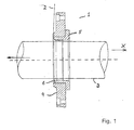
- the 1 shows a device 1 for guiding individual reinforcing threads 2 on a carrier 3, which is driven in the direction of the carrier axis X.
- the carrier 3 is in this case encompassed concentrically by the device 1.
- the device 1 has a positioning disc 4 with a plurality of thread guides which are formed by radially outwardly extending webs.
- the thread guides are arranged equidistantly distributed on a circular ring of the positioning disc 4 from each other.
- a rotationally symmetrical deflecting element 5 is arranged axially.
- the inlet side of the carrier 3 facing inner edge 6 of the deflecting element 5 is curved, so that the reinforcing threads 2 are deflected by the thread guides at an angle to the carrier 3.
- the thread guides of the positioning disc 4 are in this case arranged with respect to the deflecting element 5, that the reinforcing threads 2 are guided directly to the front side of the curved inner edges 6 and the distance in which the threads 2 free from the thread guides to the carrier 3, shortened becomes. Furthermore, by a small deflection of the inner edge 6 and only a very small Air gap to the carrier 3 prevents lateral wandering and superimposing the threads 2.
- the deflecting element 5 is pushed in the form of a sleeve in the positioning disk 4.
- FIG. 2 shows a front view of the device 1, wherein an annular cover 7 in the region of the thread guides magnetically on the surface of the positioning plate 4 is festbar.
- the cover 7 has a mounting slot 8 to release at least one selected thread guide and to allow threading a reinforcing thread 2 in the thread guide on the carrier 3.
- the cover 7 is rotated successively and the reinforcing threads 2 are guided successively through the respective thread guides. The cover 7 prevents that already threaded reinforcing threads 2 are released again from the thread passage openings.
- FIG. 3 shows a detail view of the positioning disk with magnetically attached cover disk 7.
- the thread guides 9 can be seen, which are formed by radially outwardly extending webs. The reinforcing threads 2 can thus be easily inserted into the slots.
Landscapes
- Engineering & Computer Science (AREA)
- Mechanical Engineering (AREA)
- Textile Engineering (AREA)
- Chemical & Material Sciences (AREA)
- Composite Materials (AREA)
- Moulding By Coating Moulds (AREA)
- Registering, Tensioning, Guiding Webs, And Rollers Therefor (AREA)
- Guides For Winding Or Rewinding, Or Guides For Filamentary Materials (AREA)
- Treatment Of Fiber Materials (AREA)
- Electrical Discharge Machining, Electrochemical Machining, And Combined Machining (AREA)
- Transition And Organic Metals Composition Catalysts For Addition Polymerization (AREA)
- Knitting Machines (AREA)
Description
- Die Erfindung betrifft eine Vorrichtung zum Führen einzelner Verstärkungsfäden auf einen Träger, der in Richtung der Trägerachse vortreibbar ist.
- Eine gattungsgemäße Vorrichtung ist beispielsweise aus der
DE 198 46 852 C2 bekannt und wird insbesondere für ein Spulengatter zur Einarbeitung einzelner Verstärkungsfäden in einen Schlauchrohling verwendet. Dabei wird ein Kautschukschlauch auf einem Dorn im Endlosverfahren extrudiert. Auf diese erste Kautschukschicht wird eine dichte Lage von Fäden aufspiralisiert, indem ein Spulengatter um den aus Dorn und Kautschukschlauch gebildeten Träger rotiert. Durch das Vortreiben des Trägers in Trägerachsrichtung entsteht eine spiralförmige Fadenlage mit einem Fadenwinkel, der von der Vortriebsgeschwindigkeit und der Rotationsgeschwindigkeit des Spulengatters abhängt. - Aus der
DE 198 46 852 C2 ist bekannt, dass die Fäden durch eine Reihe von Löchern geführt werden, die auf einer Umfangslinie eines Positionierrings äquidistant voneinander angeordnet sind. Durch jedes Loch wird jeweils ein Verstärkungsfaden radial nach innen geführt. Der Positionierring umfasst ein rotationssymmetrisches, trichterförmiges Umlenkelement konzentrisch. Das Umlenkelement hat einen sich stetig verjüngenden Kanal mit einer ringförmigen Eintrittsöffnung und einer kleineren ringförmigen Austrittsöffnung, wobei die Verstärkungsfäden auf der radial inneren Oberfläche des Umlenkelementes auf den Träger geführt werden, der von dem Umlenkelement umfasst wird. - Es hat sich herausgestellt, dass das Einfädeln durch Löcher sehr arbeitsintensiv ist. Weiterhin verlaufen die Verstärkungsfäden zwischen den Löchern im Positionierring und dem Träger auf einer relativ langen radialen inneren Oberfläche frei und ungeführt; weil der Positionierring einen großen Durchmesser haben muss, um alle Bohrungen unterzubringen. Hierdurch kann kein konstanter Abstand der Verstärkungsfäden auf dem Träger gewährleistet werden. Zudem ist es möglich, dass sich einzelne Verstärkungsfäden überkreuzen.
- Aufgabe der Erfindung war es daher, eine verbesserte Vorrichtung zum Führen einzelner Verstärkungsfäden zu schaffen, mit der die vorstehenden Nachteile gelöst werden.
- Die Aufgabe wird gelöst durch
- eine Positionierscheibe mit einer Vielzahl von auf einem Kreisring der Positionierscheibe verteilt angeordneten Fadenführungen, und
- ein rotationssymmetrisches Umlenkelement.
- Die Positionierscheibe und das Umlenkelement umfassen den Träger jeweils konzentrisch, wobei das Umlenkelement innerhalb der Positionierscheibe angeordnet und axial zur Positionierscheibe ausgerichtet ist. Die einlaufseitig dem Träger zugewandte umlaufende Innenkante des Umlenkelementes ist gekrümmt und die Fadenführungen der Positionierscheibe münden unmittelbar an der Stirnseite der gekrümmten Innenkante.
- Durch die Verwendung einer Positionierscheibe mit Schlitzen anstelle eines Positionierrings mit Bohrungen, der das Umlenkelement umschließt, kann der Durchmesser, auf dem die Verstärkungsfäden geführt werden, deutlich verringert werden. Hierdurch wird die Strecke, auf der die Verstärkungsfäden zwischen den Fadenführungen und dem Träger frei und ungeführt laufen, erheblich verkürzt und ein Wandern und Kreuzen der Fäden verhindert. Das arbeitsintensive Einfädeln der Verstärkungsfäden in die Bohrungen wird durch das bessere und schnellere Einlegen der Fäden in die Schlitze substituiert.
- Vorteilhafterweise sind die Fadenführungen aus sich radial erstreckende oder schräg angeordnete Stege ausgebildet. Damit kann die Anzahl der mit der Vorrichtung führbaren Verstärkungsfäden erheblich im Vergleich zu Bohrungen vergrößert werden, da nur ein Steg mit einer geringen Stärke zwischen den Schlitzen erforderlich ist, und die Verstärkungsfäden lassen sich leicht in die Schlitze einlegen.
- Vorzugsweise ist eine kreisbandförmige Abdeckscheibe lösbar, beispielsweise magnetisch, auf der Oberfläche der Positionierscheibe im Bereich der Fadenführungen montierbar. Die Abdeckscheibe verhindert, dass die Fäden aus den Fadendurchführungsöffnungen, insbesondere den Schlitzen, rutschen.
- Für das Einfädeln der Verstärkungsfäden in die Vorrichtung beim Rüsten einer Spiralisiervorrichtung ist es vorteilhaft, wenn eine Abdeckscheibe mit einem sich radial erstreckenden Schlitz auf der Oberfläche der Positionierscheibe im Bereich der Fadendurchführungsöffnungen montiert wird. Im Bereich des Schlitzes können auf diese Weise Verstärkungsfäden eingefädelt werden, während die bereits eingefädelten Verstärkungsfäden durch die Abdeckscheibe sicher gehalten werden. Insbesondere zur Erleichterung des Rüstvorgangs ist die Abdeckscheibe vorzugsweise magnetisch an die Positionierscheibe anheftbar und kann so von Schlitz zu Schlitz weiter gedreht werden.
- Die Erfindung wird nachfolgend anhand der beigefügten Zeichnungen näher erläutert. Es zeigen:
- Figur 1 -
- eine Querschnittsansicht der erfindungsgemäßen Vorrichtung zum Führen einzelner Verstärkungsfäden;
- Figur 2 -
- eine Frontansicht der Vorrichtung aus der Figur 1;
- Figur 3 -
- eine Detailansicht eines Ausschnitts aus der Figur 2.
- Die Figur 1 lässt eine Vorrichtung 1 zum Führen einzelner Verstärkungsfäden 2 auf einen Träger 3 erkennen, der in Richtung der Trägerachse X vorgetrieben wird. Der Träger 3 wird hierbei konzentrisch von der Vorrichtung 1 umfasst.
- Die Vorrichtung 1 hat eine Positionierscheibe 4 mit einer Vielzahl von Fadenführungen, die durch radial sich nach außen erstreckende Stege ausgebildet sind. Die Fadenführungen sind äquidistant auf einem Kreisring der Positionierscheibe 4 voneinander verteilt angeordnet.
- Unterhalb der Positionierscheibe 4 ist ein rotationssymmetrisches Umlenkelement 5 axial angeordnet. Die einlaufseitig dem Träger 3 zugewandte Innenkante 6 des Umlenkelementes 5 ist gekrümmt, so dass die Verstärkungsfäden 2 von den Fadenführungen winklig auf den Träger 3 umgelenkt werden. Die Fadenführungen der Positionierscheibe 4 sind hierbei derart im Bezug auf das Umlenkelement 5 angeordnet, dass die Verstärkungsfäden 2 unmittelbar an die Stirnseite der gekrümmten Innenkanten 6 geführt werden und die Strecke, in der die Fäden 2 von den Fadenführungen zu dem Träger 3 frei laufen, verkürzt wird. Weiterhin wird durch eine nur kleine Umlenkfläche der Innenkante 6 und einen nur sehr kleinen Luftspalt zum Träger 3 ein seitliches Wandern und Überlagern der Fäden 2 verhindert.
- In dem dargestellten Ausführungsbeispiel ist das Umlenkelement 5 in Form einer Hülse in die Positionierscheibe 4 geschoben.
- Die Figur 2 lässt eine Frontansicht der Vorrichtung 1 erkennen, wobei eine kreisringförmige Abdeckscheibe 7 im Bereich der Fadenführungen magnetisch auf die Oberfläche der Positionierscheibe 4 heftbar ist. Die Abdeckscheibe 7 hat einen Montageschlitz 8, um mindestens eine ausgewählte Fadenführung freizugeben und ein Einfädeln eines Verstärkungsfadens 2 in die Fadenführung auf den Träger 3 zu ermöglichen. Zum Einrüsten eines Spulengatters wird die Abdeckscheibe 7 sukzessive gedreht und die Verstärkungsfäden 2 nacheinander durch die jeweiligen Fadenführungen geführt. Die Abdeckscheibe 7 verhindert dabei, dass bereits eingefädelte Verstärkungsfäden 2 sich wieder aus den Fadendurchführungsöffnungen lösen.
- Die Figur 3 lässt eine Ausschnittsansicht der Positionierscheibe mit magnetisch angehefteter Abdeckscheibe 7 erkennen. Im Bereich des Montageschlitzes 8 der Abdeckscheibe 7 sind die Fadenführungen 9 zu erkennen, die durch sich radial nach außen erstreckende Stege gebildet sind. Die Verstärkungsfäden 2 können damit leicht in die Schlitze eingelegt werden.
Claims (5)
- Vorrichtung (1) zum Führen einzelner Verstärkungsfäden (2) auf einen Träger (3), der in Richtung der Trägerachse (X) vortreibbar ist,
wobei- eine Positionierscheibe (4) mit einer Vielzahl von auf einem Kreisring der Positionierscheibe (4) verteilt angeordneten Fadenführungen (9), und- ein rotationssymmetrisches Umlenkelement (5), undwobei- die Positionierscheibe (4) und das Umlenkelement (5) den Träger (3) jeweils konzentrisch umfassen,das Umlenkelement (5) innerhalb der Positionierscheibe (4) angeordnet und axial zur Positionierscheibe (4) ausgerichtet ist,- die einlaufseitig dem Träger (3) zugewandte umlaufende Innenkante (6) einer Stirnseite des Umlenkelementes (5) gekrümmt ist, und wobei- die Fadenführungen (9) unmittelbar an der gekrümmten Innenkante (6) münden. - Vorrichtung nach Anspruch 1, dadurch gekennzeichnet, dass die Fadenführungen (9) durch sich radial erstreckende oder schräg angeordnete Stege ausgebildet sind.
- Vorrichtung nach einem der vorhergehenden Ansprüche, gekennzeichnet durch eine kreisbandförmige Abdeckscheibe (7), die lösbar auf der Oberfläche der Positionierscheibe (4) im Bereich der Fadenführungen (9) montierbar ist.
- Vorrichtung nach Anspruch 3, dadurch gekennzeichnet, dass die Abdeckscheibe (7) einen sich radial erstreckenden Schlitz hat.
- Vorrichtung nach Anspruch 3 oder 4, dadurch gekennzeichnet, dass die Abdeckscheibe (7) magnetisch an die Positionierscheibe (4) anheftbar ist.
Applications Claiming Priority (3)
| Application Number | Priority Date | Filing Date | Title |
|---|---|---|---|
| DE10229078A DE10229078B4 (de) | 2002-06-28 | 2002-06-28 | Vorrichtung zum Führen einzelner Verstärkungsfäden |
| DE10229078 | 2002-06-28 | ||
| PCT/DE2003/001585 WO2004002719A1 (de) | 2002-06-28 | 2003-05-16 | Vorrichtung zum führen einzelner verstärkungsfäden |
Publications (2)
| Publication Number | Publication Date |
|---|---|
| EP1521670A1 EP1521670A1 (de) | 2005-04-13 |
| EP1521670B1 true EP1521670B1 (de) | 2007-10-24 |
Family
ID=29795949
Family Applications (1)
| Application Number | Title | Priority Date | Filing Date |
|---|---|---|---|
| EP03761398A Expired - Lifetime EP1521670B1 (de) | 2002-06-28 | 2003-05-16 | Vorrichtung zum führen einzelner verstärkungsfäden |
Country Status (8)
| Country | Link |
|---|---|
| US (1) | US7267152B2 (de) |
| EP (1) | EP1521670B1 (de) |
| JP (1) | JP4440770B2 (de) |
| KR (1) | KR100948992B1 (de) |
| AT (1) | ATE376491T1 (de) |
| AU (1) | AU2003232623A1 (de) |
| DE (2) | DE10229078B4 (de) |
| WO (1) | WO2004002719A1 (de) |
Family Cites Families (19)
| Publication number | Priority date | Publication date | Assignee | Title |
|---|---|---|---|---|
| DE601308C (de) * | 1928-12-19 | 1934-08-13 | Felten & Guilleaume Carlswerk | Verfahren zur Herstellung von drallarmen, spannungsfreien Fassondrahtseilen |
| US2093206A (en) * | 1935-06-27 | 1937-09-14 | Us Rubber Prod Inc | Cord covered tube and apparatus for applying cords to tubes, cores, and the like |
| US2918104A (en) * | 1957-07-05 | 1959-12-22 | Columbia Products Co | Apparatus and method for producing tapered glass rods |
| GB921486A (en) * | 1958-05-16 | 1963-03-20 | Bristol Aeroplane Plastics Ltd | Improvements in covering a mandrel with helical layers of thread |
| DE1435237C3 (de) * | 1961-03-14 | 1974-06-12 | Fa. W. & M. Ostermann, 5600 Wuppertalbarmen | Maschine zum Herstellen bewehrter Schläuche |
| US3332815A (en) * | 1964-06-15 | 1967-07-25 | Glenn G Havens | Method and apparatus for continuously forming elongated hollow articles |
| US3378427A (en) * | 1964-06-26 | 1968-04-16 | Smith Corp A O | Apparatus for winding articles |
| FR1546791A (fr) * | 1967-10-13 | 1968-11-22 | Sediver | Profilés et stratifiés destinés à être utilisés comme éléments de structure électromécanique et notamment comme isolateurs |
| GB1497834A (en) * | 1974-06-05 | 1978-01-12 | Montagut Guix J Salvador | Manufacture of elongated hollow bodies from fibre-reinforced synthetic resins |
| US4172562A (en) * | 1976-12-23 | 1979-10-30 | Union Carbide Corporation | Process for winding filaments on a mandrel |
| US4288267A (en) * | 1980-01-21 | 1981-09-08 | Mcclean Anderson, Inc. | Preliminary and end winding method and apparatus |
| US4361459A (en) * | 1981-04-22 | 1982-11-30 | Bristol Composite Materials Engineering Limited | Resin impregnator for filament wound pipe |
| US4432302A (en) * | 1982-05-05 | 1984-02-21 | Mcdonnell Douglas Corporation | Resin impregnation ring |
| US4494436A (en) * | 1983-09-02 | 1985-01-22 | Elfin Corporation | Apparatus for manufacturing resin impregnated fiber braided products |
| GB8403965D0 (en) * | 1984-02-15 | 1984-03-21 | Secr Defence | Filament winding |
| GB2171073A (en) * | 1985-02-19 | 1986-08-20 | Stc Plc | Binding head |
| DE19846852C2 (de) * | 1998-10-12 | 2001-07-26 | Contitech Holding Gmbh | Vorrichtung zur Einarbeitung einzelner Verstärkungsfäden in einen Schlauchrohling und Verfahren zur Herstellung eines fadenverstärkten Schlauchrohlings mit Hilfe der Vorrichtung |
| US6494980B1 (en) | 1998-10-12 | 2002-12-17 | Contitech Luftfedersysteme Gmbh | Device for incorporating individual reinforcing threads into an unfinished tube and process for manufacturing a thread-reinforced unfinished tube with the aid of this device |
| US6263937B1 (en) * | 1999-05-27 | 2001-07-24 | Are Industries, Inc. | Apparatus for making resin-impregnated fiber substrates |
-
2002
- 2002-06-28 DE DE10229078A patent/DE10229078B4/de not_active Expired - Fee Related
-
2003
- 2003-05-16 WO PCT/DE2003/001585 patent/WO2004002719A1/de not_active Ceased
- 2003-05-16 EP EP03761398A patent/EP1521670B1/de not_active Expired - Lifetime
- 2003-05-16 US US10/518,850 patent/US7267152B2/en not_active Expired - Lifetime
- 2003-05-16 KR KR1020047021245A patent/KR100948992B1/ko not_active Expired - Fee Related
- 2003-05-16 AT AT03761398T patent/ATE376491T1/de not_active IP Right Cessation
- 2003-05-16 JP JP2004516453A patent/JP4440770B2/ja not_active Expired - Fee Related
- 2003-05-16 DE DE50308467T patent/DE50308467D1/de not_active Expired - Lifetime
- 2003-05-16 AU AU2003232623A patent/AU2003232623A1/en not_active Abandoned
Also Published As
| Publication number | Publication date |
|---|---|
| JP2005531431A (ja) | 2005-10-20 |
| JP4440770B2 (ja) | 2010-03-24 |
| US20050127230A1 (en) | 2005-06-16 |
| ATE376491T1 (de) | 2007-11-15 |
| DE10229078B4 (de) | 2006-07-13 |
| KR20050014024A (ko) | 2005-02-05 |
| AU2003232623A1 (en) | 2004-01-19 |
| US7267152B2 (en) | 2007-09-11 |
| WO2004002719A1 (de) | 2004-01-08 |
| KR100948992B1 (ko) | 2010-03-23 |
| DE10229078A1 (de) | 2004-01-29 |
| EP1521670A1 (de) | 2005-04-13 |
| DE50308467D1 (de) | 2007-12-06 |
Similar Documents
| Publication | Publication Date | Title |
|---|---|---|
| WO1996035523A1 (de) | Hydrodynamische düse für die reinigung von rohren und kanälen | |
| EP0843880A1 (de) | Spulenträger | |
| DE3923305C2 (de) | Zylindrische Spulhülse | |
| DE10229074A1 (de) | Spiralisiervorrichtung | |
| DE102013216127B4 (de) | Strömungsverdämmungselement, insbesondere zur Luftströmungsverdämmung in einem Luftkanalsystem eines Fahrzeugs | |
| EP3052683B1 (de) | Spinnstelle einer luftspinnmaschine mit einem faserführungselement | |
| DE10229078B4 (de) | Vorrichtung zum Führen einzelner Verstärkungsfäden | |
| DE102015119112A1 (de) | Fadenabzugsdüse mit radial zur Düsenbohrung verlaufenden Kerben | |
| EP0620872B1 (de) | Verfahren und vorrichtung zum texturieren von thermoplastischen fäden | |
| EP0217097A2 (de) | Spinnschacht mit perforierter Teillänge in Düsennähe | |
| DE10393063B4 (de) | Fadenabzugsdüse | |
| EP1099531B1 (de) | Vorrichtung zur Einarbeitung einzelner Verstärkungsfäden in einem Schlauchrohling und Verfahren zur Herstellung eines fadenverstärkten Schlauchrohlings mit Hilfe der Vorrichtung | |
| EP3827963B1 (de) | Vorrichtung zum filtrieren eines fluids, insbesondere einer verunreinigungen aufweisenden kunststoff-schmelze, sowie ventilanordnung für ein solches fluid | |
| EP0775769A1 (de) | Vorrichtung zum Klemmen eines Unterwindefadens an der Spindel einer Ringspinn- oder -zwirnmaschine | |
| DE2851228C2 (de) | Abstreifer zum Entfernen von Unterwindungen von dem Unterwindebereich einer Ringspinn- oder -zwirnspindel | |
| DE10202788A1 (de) | Texturieranlage und Texturierdüse hierfür | |
| EP4101965B1 (de) | Fadenbremse | |
| DE102005022686A1 (de) | Vorrichtung zum Herstellen eines gesponnenen Fadens | |
| EP0506998B1 (de) | Gewindeverschluss für Garnbegrenzungsscheiben | |
| DE102020112972A9 (de) | Fadenballoneinengungseinheit für eine Textilmaschine | |
| DE4117704C2 (de) | Abreißvorrichtung zum Abreißen von Garnen oder Zwirnen an einer Spinn- oder Zwirnmaschine | |
| DE202005001809U1 (de) | Lochplatte für einen Unterwassergranulator | |
| EP4382822A1 (de) | Einbaurahmen für lüftungskomponenten in einer decke | |
| DE10132865B4 (de) | Trennfadenführer für eine Spinnanlage und Spinnanlage mit einem solchen Trennfadenführer | |
| DE102008024079A1 (de) | Texturierdüse |
Legal Events
| Date | Code | Title | Description |
|---|---|---|---|
| PUAI | Public reference made under article 153(3) epc to a published international application that has entered the european phase |
Free format text: ORIGINAL CODE: 0009012 |
|
| 17P | Request for examination filed |
Effective date: 20050128 |
|
| AK | Designated contracting states |
Kind code of ref document: A1 Designated state(s): AT BE BG CH CY CZ DE DK EE ES FI FR GB GR HU IE IT LI LU MC NL PT RO SE SI SK TR |
|
| AX | Request for extension of the european patent |
Extension state: AL LT LV MK |
|
| DAX | Request for extension of the european patent (deleted) | ||
| GRAP | Despatch of communication of intention to grant a patent |
Free format text: ORIGINAL CODE: EPIDOSNIGR1 |
|
| GRAS | Grant fee paid |
Free format text: ORIGINAL CODE: EPIDOSNIGR3 |
|
| GRAA | (expected) grant |
Free format text: ORIGINAL CODE: 0009210 |
|
| AK | Designated contracting states |
Kind code of ref document: B1 Designated state(s): AT BE BG CH CY CZ DE DK EE ES FI FR GB GR HU IE IT LI LU MC NL PT RO SE SI SK TR |
|
| REG | Reference to a national code |
Ref country code: GB Ref legal event code: FG4D Free format text: NOT ENGLISH |
|
| REG | Reference to a national code |
Ref country code: CH Ref legal event code: EP |
|
| REG | Reference to a national code |
Ref country code: IE Ref legal event code: FG4D Free format text: LANGUAGE OF EP DOCUMENT: GERMAN |
|
| REF | Corresponds to: |
Ref document number: 50308467 Country of ref document: DE Date of ref document: 20071206 Kind code of ref document: P |
|
| NLV1 | Nl: lapsed or annulled due to failure to fulfill the requirements of art. 29p and 29m of the patents act | ||
| PG25 | Lapsed in a contracting state [announced via postgrant information from national office to epo] |
Ref country code: ES Free format text: LAPSE BECAUSE OF FAILURE TO SUBMIT A TRANSLATION OF THE DESCRIPTION OR TO PAY THE FEE WITHIN THE PRESCRIBED TIME-LIMIT Effective date: 20080204 Ref country code: NL Free format text: LAPSE BECAUSE OF FAILURE TO SUBMIT A TRANSLATION OF THE DESCRIPTION OR TO PAY THE FEE WITHIN THE PRESCRIBED TIME-LIMIT Effective date: 20071024 Ref country code: SE Free format text: LAPSE BECAUSE OF FAILURE TO SUBMIT A TRANSLATION OF THE DESCRIPTION OR TO PAY THE FEE WITHIN THE PRESCRIBED TIME-LIMIT Effective date: 20080124 |
|
| GBV | Gb: ep patent (uk) treated as always having been void in accordance with gb section 77(7)/1977 [no translation filed] | ||
| PG25 | Lapsed in a contracting state [announced via postgrant information from national office to epo] |
Ref country code: BG Free format text: LAPSE BECAUSE OF FAILURE TO SUBMIT A TRANSLATION OF THE DESCRIPTION OR TO PAY THE FEE WITHIN THE PRESCRIBED TIME-LIMIT Effective date: 20080124 Ref country code: SI Free format text: LAPSE BECAUSE OF FAILURE TO SUBMIT A TRANSLATION OF THE DESCRIPTION OR TO PAY THE FEE WITHIN THE PRESCRIBED TIME-LIMIT Effective date: 20071024 Ref country code: PT Free format text: LAPSE BECAUSE OF FAILURE TO SUBMIT A TRANSLATION OF THE DESCRIPTION OR TO PAY THE FEE WITHIN THE PRESCRIBED TIME-LIMIT Effective date: 20080324 |
|
| REG | Reference to a national code |
Ref country code: IE Ref legal event code: FD4D |
|
| ET | Fr: translation filed | ||
| PG25 | Lapsed in a contracting state [announced via postgrant information from national office to epo] |
Ref country code: DK Free format text: LAPSE BECAUSE OF FAILURE TO SUBMIT A TRANSLATION OF THE DESCRIPTION OR TO PAY THE FEE WITHIN THE PRESCRIBED TIME-LIMIT Effective date: 20071024 Ref country code: CZ Free format text: LAPSE BECAUSE OF FAILURE TO SUBMIT A TRANSLATION OF THE DESCRIPTION OR TO PAY THE FEE WITHIN THE PRESCRIBED TIME-LIMIT Effective date: 20071024 |
|
| PG25 | Lapsed in a contracting state [announced via postgrant information from national office to epo] |
Ref country code: SK Free format text: LAPSE BECAUSE OF FAILURE TO SUBMIT A TRANSLATION OF THE DESCRIPTION OR TO PAY THE FEE WITHIN THE PRESCRIBED TIME-LIMIT Effective date: 20071024 Ref country code: RO Free format text: LAPSE BECAUSE OF FAILURE TO SUBMIT A TRANSLATION OF THE DESCRIPTION OR TO PAY THE FEE WITHIN THE PRESCRIBED TIME-LIMIT Effective date: 20071024 |
|
| PLBE | No opposition filed within time limit |
Free format text: ORIGINAL CODE: 0009261 |
|
| STAA | Information on the status of an ep patent application or granted ep patent |
Free format text: STATUS: NO OPPOSITION FILED WITHIN TIME LIMIT |
|
| 26N | No opposition filed |
Effective date: 20080725 |
|
| PG25 | Lapsed in a contracting state [announced via postgrant information from national office to epo] |
Ref country code: IE Free format text: LAPSE BECAUSE OF FAILURE TO SUBMIT A TRANSLATION OF THE DESCRIPTION OR TO PAY THE FEE WITHIN THE PRESCRIBED TIME-LIMIT Effective date: 20071024 |
|
| PG25 | Lapsed in a contracting state [announced via postgrant information from national office to epo] |
Ref country code: GB Free format text: LAPSE BECAUSE OF FAILURE TO SUBMIT A TRANSLATION OF THE DESCRIPTION OR TO PAY THE FEE WITHIN THE PRESCRIBED TIME-LIMIT Effective date: 20071024 |
|
| BERE | Be: lapsed |
Owner name: CONTITECH LUFTFEDERSYSTEME G.M.B.H. Effective date: 20080531 |
|
| PG25 | Lapsed in a contracting state [announced via postgrant information from national office to epo] |
Ref country code: MC Free format text: LAPSE BECAUSE OF NON-PAYMENT OF DUE FEES Effective date: 20080531 |
|
| REG | Reference to a national code |
Ref country code: CH Ref legal event code: PL |
|
| PG25 | Lapsed in a contracting state [announced via postgrant information from national office to epo] |
Ref country code: EE Free format text: LAPSE BECAUSE OF FAILURE TO SUBMIT A TRANSLATION OF THE DESCRIPTION OR TO PAY THE FEE WITHIN THE PRESCRIBED TIME-LIMIT Effective date: 20071024 Ref country code: CH Free format text: LAPSE BECAUSE OF NON-PAYMENT OF DUE FEES Effective date: 20080531 Ref country code: LI Free format text: LAPSE BECAUSE OF NON-PAYMENT OF DUE FEES Effective date: 20080531 Ref country code: GR Free format text: LAPSE BECAUSE OF FAILURE TO SUBMIT A TRANSLATION OF THE DESCRIPTION OR TO PAY THE FEE WITHIN THE PRESCRIBED TIME-LIMIT Effective date: 20080125 |
|
| PG25 | Lapsed in a contracting state [announced via postgrant information from national office to epo] |
Ref country code: FI Free format text: LAPSE BECAUSE OF FAILURE TO SUBMIT A TRANSLATION OF THE DESCRIPTION OR TO PAY THE FEE WITHIN THE PRESCRIBED TIME-LIMIT Effective date: 20071024 |
|
| PG25 | Lapsed in a contracting state [announced via postgrant information from national office to epo] |
Ref country code: BE Free format text: LAPSE BECAUSE OF NON-PAYMENT OF DUE FEES Effective date: 20080531 |
|
| PG25 | Lapsed in a contracting state [announced via postgrant information from national office to epo] |
Ref country code: CY Free format text: LAPSE BECAUSE OF FAILURE TO SUBMIT A TRANSLATION OF THE DESCRIPTION OR TO PAY THE FEE WITHIN THE PRESCRIBED TIME-LIMIT Effective date: 20071024 |
|
| PG25 | Lapsed in a contracting state [announced via postgrant information from national office to epo] |
Ref country code: AT Free format text: LAPSE BECAUSE OF NON-PAYMENT OF DUE FEES Effective date: 20080516 |
|
| PG25 | Lapsed in a contracting state [announced via postgrant information from national office to epo] |
Ref country code: HU Free format text: LAPSE BECAUSE OF FAILURE TO SUBMIT A TRANSLATION OF THE DESCRIPTION OR TO PAY THE FEE WITHIN THE PRESCRIBED TIME-LIMIT Effective date: 20080425 Ref country code: LU Free format text: LAPSE BECAUSE OF NON-PAYMENT OF DUE FEES Effective date: 20080516 |
|
| PG25 | Lapsed in a contracting state [announced via postgrant information from national office to epo] |
Ref country code: TR Free format text: LAPSE BECAUSE OF FAILURE TO SUBMIT A TRANSLATION OF THE DESCRIPTION OR TO PAY THE FEE WITHIN THE PRESCRIBED TIME-LIMIT Effective date: 20071024 |
|
| PG25 | Lapsed in a contracting state [announced via postgrant information from national office to epo] |
Ref country code: IT Free format text: LAPSE BECAUSE OF NON-PAYMENT OF DUE FEES Effective date: 20080531 |
|
| REG | Reference to a national code |
Ref country code: FR Ref legal event code: PLFP Year of fee payment: 13 |
|
| REG | Reference to a national code |
Ref country code: FR Ref legal event code: PLFP Year of fee payment: 14 |
|
| REG | Reference to a national code |
Ref country code: FR Ref legal event code: PLFP Year of fee payment: 15 |
|
| REG | Reference to a national code |
Ref country code: FR Ref legal event code: PLFP Year of fee payment: 16 |
|
| PGFP | Annual fee paid to national office [announced via postgrant information from national office to epo] |
Ref country code: FR Payment date: 20200522 Year of fee payment: 18 |
|
| PG25 | Lapsed in a contracting state [announced via postgrant information from national office to epo] |
Ref country code: FR Free format text: LAPSE BECAUSE OF NON-PAYMENT OF DUE FEES Effective date: 20210531 |
|
| PGFP | Annual fee paid to national office [announced via postgrant information from national office to epo] |
Ref country code: DE Payment date: 20220531 Year of fee payment: 20 |
|
| REG | Reference to a national code |
Ref country code: DE Ref legal event code: R119 Ref document number: 50308467 Country of ref document: DE |
|
| PG25 | Lapsed in a contracting state [announced via postgrant information from national office to epo] |
Ref country code: DE Free format text: LAPSE BECAUSE OF NON-PAYMENT OF DUE FEES Effective date: 20221201 |