EP1521209B1 - Radiation image enhancement - Google Patents
Radiation image enhancement Download PDFInfo
- Publication number
- EP1521209B1 EP1521209B1 EP04104576.6A EP04104576A EP1521209B1 EP 1521209 B1 EP1521209 B1 EP 1521209B1 EP 04104576 A EP04104576 A EP 04104576A EP 1521209 B1 EP1521209 B1 EP 1521209B1
- Authority
- EP
- European Patent Office
- Prior art keywords
- feature amount
- value
- image
- evaluating
- image processing
- Prior art date
- Legal status (The legal status is an assumption and is not a legal conclusion. Google has not performed a legal analysis and makes no representation as to the accuracy of the status listed.)
- Expired - Lifetime
Links
Images


Classifications
-
- G—PHYSICS
- G06—COMPUTING OR CALCULATING; COUNTING
- G06T—IMAGE DATA PROCESSING OR GENERATION, IN GENERAL
- G06T5/00—Image enhancement or restoration
- G06T5/90—Dynamic range modification of images or parts thereof
- G06T5/92—Dynamic range modification of images or parts thereof based on global image properties
-
- G—PHYSICS
- G06—COMPUTING OR CALCULATING; COUNTING
- G06T—IMAGE DATA PROCESSING OR GENERATION, IN GENERAL
- G06T2207/00—Indexing scheme for image analysis or image enhancement
- G06T2207/10—Image acquisition modality
- G06T2207/10116—X-ray image
- G06T2207/10121—Fluoroscopy
Definitions
- the present invention relates to an image processing method, an image processing apparatus and an image processing program all relating to processing of radiation images, and in particular, to an image processing method, an image processing apparatus and an image processing program all making it possible to obtain radiation images suitable for diagnoses.
- a radiation image detecting apparatus obtained by generating electric charges corresponding to intensity of radiated radiation, then, accumulating the generated electric charges on plural capacitors arranged in a two-dimensional way, and thereby, by taking out the accumulated electric charges.
- FPD flat panel detectors
- Patent Document 2 describes that appropriate image processing is conducted by after establishing image processing conditions based on the state of distribution of a high signal value area and a low signal value area.
- a ratio of a high density area (area where an amount of transmitted radiation is large) to a low density area (area where an amount of transmitted radiation is small) varies greatly depending on the radiographed region of a subject.
- density in a lung field varies greatly depending on the state of a patient, for example, the state of breathing.
- the image when the low density area is dominant, the image is totally of high density because the standard value is a low value, while, when the high density area is dominant, the image is totally of low density because the standard value is a high value.
- a portion necessary for diagnoses includes a high density area and a low density area, and therefore, it is not preferable for diagnosing that the total density is one-sided to low density or high density.
- a parameter of image processing is determined in the way to be given single-mindedly as a signal value or a parameter determined based on a single value or a histogram of a specific area (an area of interest) in images, and when the area or the parameter obtained is inappropriate, there has been an occasion where inappropriate image processing is obtained.
- the invention has been achieved in view of the problems stated above, and its object is to realize an image processing method, an image processing apparatus and an image processing program all making it possible to prevent occurrence of circumstances where a failure in determining processing conditions for image forming makes it difficult to diagnose, and to conduct image processing under the appropriate condition or the condition close to the appropriate one, in any occasion.
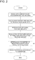
- a feature amount of a radiation image is calculated, the calculated feature amount is evaluated by a feature amount evaluating function, a parameter of image processing is determined based on results of the evaluation of the evaluated feature amount, and image processing is carried out by the determined parameter.
- image processing is carried out by the parameter evaluated and determined based on the feature amount of each radiation image, therefore, appropriate image processing can be carried out by conducting weighting corresponding to importance based on a feature amount for each signal value, by calculating an amplification factor of the signal in the case of converting with LUT for gradation processing of each pixel, and by determining LUT with which the total sum of the value obtained by multiplying the amplification factor and weight together for all pixels becomes maximum, for example.
- the importance based on the feature amount in this case is an amount determined based on the centricity degree value measuring a distance from the image center as the feature amount and edge intensity in each pixel detected by using a differential filter, because an important point for diagnosis is positioned at the center of the image generally in many cases and it further has an edge component, for example.
- a gradient of LUT and an amount corresponding to the gradient at each pixel value can be considered.
- An image processing method of obtaining a suitable image for diagnosis using a radiation image having signals according to an irradiation amount of a radiation ray transmitting through a subject comprises: a feature amount calculating step of calculating a feature amount of the radiation image; a feature amount evaluating step of evaluating the feature amount calculated with a feature amount evaluating function in the feature amount calculating step; a parameter determining step of determining a parameter for an image processing based on a result evaluated in the feature amount evaluating step; and an image processing step of processing an image using the parameter determined in the parameter determining step.
- the image processing method of Item (1) wherein the image processing in the image processing step is a gradation processing and the feature amount is evaluated by the feature amount evaluating function referring to the gradation processing condition in the gradation processing.
- the feature amount of the radiation image obtained in the feature amount calculating step is based on at least one of a statistic value of a predefined region around each pixel, a difference of values of adjacent pixels or pixels positioned predefined number of pixels apart and an edge component extracted from of all or a part of the radiation image, and wherein the feature amount evaluating function is determined based on a variation of the feature amount when the radiation image is converted using a converting method parameterized by one or more variables.
- the statistic value is a maximum or a minimum value of a predefined region around each pixel.
- the edge component is extracted by a high frequency region extracting filter.
- the high frequency region extracting filter is a differentiation filter.
- the high frequency region extracting filter is a Laplacian filter.
- the image processing method of Item (4) the edge component is extracted by a Laplacian pyramid method.
- the image processing method of Item (4) the edge component is extracted by a wavelet analysis.
- the image processing method of Item (4) wherein the feature amount is determined by a set of the feature amount of Item (5) - (13) and at least one of a value calculated by adding, multiplying and subtracting a constant to the feature amount of Item (5) - (13), wherein the feature amount evaluating function is determined based on a variation of the feature amount when the radiation image is converted using a converting method parameterized by one or more variables.
- the image processing method of Item (4) wherein the parameterized image converting method converts pixel values using a lookup table for providing the gradation processing.
- An image processing apparatus for obtaining a suitable image for diagnosis using a radiation image having signals according to an irradiation amount of a radiation ray transmitting through a subject, the image processing appratus comprising: feature amount calculating means of calculating a feature amount of the radiation image; feature amount evaluating means of evaluating the feature amount calculated with a feature amount evaluating function in the feature amount calculating means; parameter determining means of determining a parameter for an image processing based on a result evaluated in the feature amount evaluating means; and image processing means of processing an image using the parameter determined in the parameter determining means.
- the feature amount of the radiation image obtained in the feature amount calculating means is based on at least one of a statistic value of a predefined region around each pixel, a difference of values of adjacent pixels or pixels positioned predefined number of pixels apart and an edge component extracted from of all or a part of the radiation image, and wherein the feature amount evaluating function is determined based on a variation of the feature amount when the radiation image is converted using a converting method parameterized by one or more variables.
- the statistic value is a maximum or a minimum value of a predefined region around each pixel.
- the high frequency region extracting filter is a differentiation filter.
- the high frequency region extracting filter is a Laplacian filter.
- An image processing program to obtain a suitable image for diagnosis using a radiation image having signals according to an irradiation amount of a radiation ray transmitting through a subject, the image processing program comprising: a feature amount calculating routine for calculating a feature amount of the radiation image; a feature amount evaluating routine for evaluating the feature amount calculated with a feature amount evaluating function in the feature amount calculating routine; a parameter determining routine for determining a parameter for an image processing based on a result evaluated in the feature amount evaluating routine; and an image processing routine for processing an image using the parameter determined in the parameter determining routine.
- the statistic value is a maximum or a minimum value of a predefined region around each pixel.
- the image processing program of Item (45), the high frequency region extracting filter is a differentiation filter.
- the image processing program of Item (45), the high frequency region extracting filter is a Laplacian filter.
- the image processing program of Item (40), the edge component is extracted by a Laplacian pyramid method.
- each means in the present embodiment can be composed of a hardware, a firmware or a software. Therefore, there is shown Fig. 1 representing a functional block diagram showing processing procedures including each step of the image processing method, each means of the image processing apparatus and each routine in the image processing program.
- each means in Fig. 1 shows not only each means of the image forming apparatus but also each step of the image processing method and each routine of the image processing program.
- Radiation generator 30, radiation image reader 40 and image processing apparatus 100 are provided as shown in Fig. 1 .
- control means 101 Inside the image processing apparatus 100, there are provided control means 101, image data generating means 110, feature amount calculating means 120, feature amount integrating means 130, feature amount evaluating means 140 and parameter determining means 150, as shown in Fig. 1 .
- information such as radiographed regions or the radiographing direction is acquired first from a user interface. Acquisition of the information is carried out when a user specifies radiographed regions. For example, information is acquired by pressing a button on which a radiographed region is indicated on a user interface (not shown) of the image processing apparatus provided with a display section and a touch panel. In addition to the foregoing, acquisition of information is performed by utilizing a magnetic card, a bar code and HIS (Intra-hospital Information System: information control by network).
- HIS Advanced Information System
- Radiation generator 30 is controlled by control means 101, and radiation emitted from the radiation generator 30 is projected on an image pick-up panel mounted on the front surface of radiation image reader 40 through subject 5.
- radiation image reader 40 radiation transmitted through subject 5 is detected, and acquired as an image signal.
- those described in TOKKAIHEI No. 11-142998 and TOKKAI No. 2002-156716 represent one wherein a photostimulable fluorescent plate is used.
- those employing a flat panel detector (FPD) as an input device include those described in TOKKAIHEI No. 6-342098 wherein detected X-rays are converted directly into electric charges and acquired as image signals, and those described in TOKKAIHEI No. 9-90048 wherein detected X-rays are converted once into light, and then, the light is received and converted into electric charges.
- FPD flat panel detector
- the radiation image reader 40 may be of the structure wherein a silver halide film on which a radiation image is recorded is irradiated with light emitted from a light source such as a laser or a fluorescent lamp, and transmitted light coming from the silver halide film is converted photoelectrically to generate image data. It is further possible to employ the structure wherein radiation energy is converted directly into an electric signal by the use of a radiation quantum digital detector to generate image data.
- an irradiation field reduction wherein radiation non-transmission substance such as a lead plate is provided on a part of subject 5 or on the radiation generator 30 to restrict an irradiation field of radiation for the subject 5, in order to prevent that a portion which is not necessary for diagnoses is irradiated with radiation, or to prevent that a portion which is not necessary for diagnoses is irradiated with radiation and the radiation scattered in that place enters the portion that is necessary for diagnoses to lower the resolving power.
- radiation non-transmission substance such as a lead plate
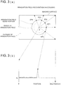
- differential processing for example, is conducted by using image data on a segment that connects prescribed position P on an imaging surface and an end portion side on the imaging surface as shown in Fig. 3(a) .
- Differentiation signal Sd obtained by the differential processing has a signal level that is great at the irradiation field edge portion as shown in Fig. 3(b) , and therefore, one irradiation field edge candidate point P1 is obtained by distinguishing the signal level of the differentiation signal Sd.
- a plurality of irradiation field edge candidate points EP1 - Epk are obtained.
- adjoining edge candidate points of these plural irradiation field edge candidate points EP1 - Epk thus obtained by a straight line or a curved line an irradiation field edge portion can be obtained.
- the variance becomes the highest, because a portion where the dose of radiation is the smallest and a portion of the dose of radiation modulated by the subject coexist. Owing to this, a small area including the irradiation field edge portion can be distinguished by the variance.
- the method disclosed by TOKKAIHEI No. 7-181609 can also be used.
- image data are rotated on the prescribed rotation center, and the rotation is continued until the moment when the parallel condition detecting means detects that a boundary line of the irradiation field is in parallel with the axis of coordinates of the rectangular coordinates, and after the parallel condition is detected, the straight line equation of the boundary before the rotation is calculated by the straight line equation calculating means based on the rotation angle and the distance from the rotation center to the boundary line. After that, by determining the area surrounded by plural boundary lines from the straight line equation, an area of the irradiation field can be distinguished.
- one boundary point is extracted by a boundary point extracting means based on image data, and a next boundary point is extracted from a group of boundary candidate points around the aforementioned boundary point.
- an area (hereinafter referred to as "a region of interest") for determining the distribution of the level of image data DT from the radiation image reader is established.
- the region of interest is established on the entire lung field so that all important areas for diagnoses may be included.
- an mean profile in the horizontal direction in an area covering 1/3 - 2/3 of the image is prepared as shown in Fig. 7 , for example, and the minimum value P on the center of the image is determined first.
- the maximum value is detected toward both ends of the image (A and B in Fig. 7 ).
- left and right ends of the region of interest are determined by searching the point of prescribed rate between the maximum value and the minimum value toward the image end from each maximum value.
- a left and a right end can be determined properly. Further, an mean profile in the vertical direction within a range of the right and left ends thus obtained is prepared, then, processing identical to that in the horizontal direction is conducted, and X, Y and Q in the drawing are detected, and thereby, an upper end and a lower end can be determined.
- a method to establish the region of interest on the center of the image of region of interest considering that an important portion for diagnoses is radiographed at the center of an image, and a method to establish the total irradiation field to be the region of interest when an important portion for diagnoses is broad like a head.
- feature amount calculating means 130 calculates a feature amount in the radiation image.
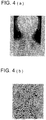
- a feature amount for example, an absolute value of an edge component obtained by conducting, on the image, the filter processing for extracting a high frequency area such as a differential filter or a Laplacian filter can be regarded as contrast on an edge area of the image.
- Fig. 4(a) is an original image of the cervical vertebrae
- Fig. 4(b) is the situation showing edges extracted from the image of the cervical vertebrae shown in Fig. 4(a) .
- the degree of contrast can be used as a weight to each pixel.
- Concerning how to give the merit marks in this case, when an absolute value, for example, is not higher than certain threshold value A determined experientially, a value of the absolute value is used as the merit mark, and when an absolute value is not lower than A, the merit mark is made to be 0.
- the function shown in Fig. 8 may also be employed by using threshold value A for obtaining a smooth change.
- a value obtained by summing up values of weighting calculated by the aforesaid contrast for all edge areas may be used for evaluating the feature amount.
- a feature amount there are considered, for example, image average density, a variance of pixel signal value within an image and an extent of the center (extent of how close to the center (image center)). Further, the following items are considered.
- the feature amount integrating means 130 integration is carried out so that the combination which is more important for diagnoses may be taken seriously. Owing to this, it is possible to conduct processing wherein the area that is necessary for diagnoses is taken seriously.
- the feature amount C can be given with the following expression.
- C A P , W _ 1, W _ 2 P x , y + A P , W _ 1, W _ 2 W _ 1 x , y + A P , W _ 1, W _ 2 W _ 2 x , y
- the sum of C on total of all edge areas can be used for evaluating the feature amount.
- feature amount evaluating means 140 evaluates the feature amount calculated by feature amount calculating means 120 and integrated by feature amount integrating means 130 by means of a feature amount evaluating function.
- f represents the feature amount evaluating function for each pixel
- ⁇ x represents microscopic changes of pixel value or feature amount value in x
- a length of the section (x - ⁇ , x + ⁇ ) is expressed specifically by one wherein addition or subtraction is applied on certain value ⁇ with x serving as the center.
- ⁇ x' represents microscopic changes of x' representing a value of X after passing of LUT that represents a look-up table which determines gradation characteristics
- a length of section (LUT(x - ⁇ ), LUT(x + ⁇ )) is expressed specifically, if LUT(x) represents a value after conversion of x by LUT.
- W(x) on the other hand is a weight of x.
- Fig. 5(a) shows an example of ⁇ x1 and ⁇ x1' in x1 and of ⁇ x2 and ⁇ x2' in x2.
- Such a feature amount evaluating function for each pixel f is put in operation on all points regarded as edges to calculate ⁇ .
- Such a feature amount evaluating function for each pixel f has characteristics shown, for example, in Fig. 6(a) or Fig. 6(b) .
- edge detection processing is conducted on the image after the feature amount conversion by a look-up table with certain SG values, with valuables such as shift value S and gradation value G of a look-up table (see Fig. 5(b) ) that determines gradation characteristics, to obtain the ratio of edges.
- SG values when an image is converted by LUT(Ax - B) for LUT that is a base, gradation value G is defined to be A, and shift value S is defined to be B.
- E' S , G EDGE S , G / ORG _ E ' S , G
- EDGE(S, G) is average contrast of the image after look-up table conversion
- ORG_E'(S, G) is average contrast of the original image.
- This contrast is not one to be obtained directly from the image, but it may be one to evaluate how an amplitude of the agreed value has been changed after passing of the look-up table at the edge point exceeding a certain threshold value, under the input which is of a fixed value constantly. Namely, the foregoing is as follows.
- E(S, G) ⁇ ⁇ (LUT(S, G, x + A1) - LUT(S, G, x - A1) ) / (2 ⁇ A) ⁇ W(x) ⁇ ... (AA).
- A1 in this case is a constant representing a microscopic section in pixel value x, and an extremely small value such as 5 is selected for the image with gradation of 12 bits, for example.
- W(x) is a weight indicating importance for each pixel
- LUT(S, G, x) represents an output value in the case of converting point x in the image with a look-up table at given SG values
- ⁇ represents the sum of detected edge points on all areas.
- E" (S) ⁇ ⁇ VAR(S) / ORG_V(S) ⁇ holds.
- VAR(S) represents average variance after conversion
- ORG_V(S) represents variance of the original image
- ⁇ represents the sum of points in the area having thereon images.
- E'"(S) AVE(S, G) - A2 holds.
- AVE(S, G) represents an average signal value after conversion
- A2 represents a constant.
- parameter determining means 150 obtains S value and G value which make E(S, G) representing the results of the evaluation conducted by feature amount evaluating means 140 with the feature amount evaluating function to be the maximum or the minimum.
- the feature amount is made to be dispersion, for example, it is possible to determine S value, by making the evaluating function to be the minimum, so that fluctuations of images in a certain area may be the smallest.
- the feature amount is an average value
- the contrast amplification factor in the totally important area of images after conversion and an average value to be in the desired condition, by combining a plurality of the evaluation results of the feature amount stated above without using each of them individually.
- EA(S) represents an average value
- it is possible to calculate higher marks when contrast is greater and density is more close to prescribed value A4, and thereby to determine LUT where an average pixel value is close to A4 and contrast amplification factor is high, by making E"'''(S, G) EA(S) ⁇ ES(S, G) to be the evaluating function.
- frequency enhancement processing and equalization processing in addition to the pixel value conversion by means of a look-up table for gradation processing are considered as the parameterized converting method.
- These processing are disclosed in detail by TOKKAI No. 2001-120524 , TOKKAISHO No. 62-62373 , TOKKAIHEI No. 9-44645 and Patent Document No. 266318 .
- appropriate parameters for these processing can be determined.
- frequency enhancement processing can be determined by enhancement coefficient ⁇ and by absolute value of gradient K of signal correction function in equalization processing.
- EF( ⁇ ) ⁇ EDGE ( ⁇ ) / EDGE_ORG( ⁇ ) ⁇ / ⁇ ⁇ VAR( ⁇ ) / ORG_V( ⁇ ) ⁇ - A5 is selected as the evaluating function of the frequency enhancement processing, an extent of enhancement can be determined so that a ratio of an edge amplification factor to the pixel variance may always be close to specific value A5, and enhancement of the edge and granularity of images can be controlled.
- EDGE_ORG( ⁇ ) represents average contrast of the original image
- EDGE( ⁇ ) represents average contrast after frequency enhancement processing
- VAR( ⁇ ) represents image average variance after frequency enhancement
- ORG_V( ⁇ ) represents an average signal value of the original image
- A represents a constant determined experientially.
- D_ORG(K) represents a dynamic range of an original image (maximum signal value - minimum signal value in the image)
- D(K) represents a dynamic range after equalization processing
- L(K, x) represents a value obtained by converting a value after equalization processing for pixel x with LUT
- the expression EF(K) ⁇ ⁇ (L(K, x + A6) - L(K, x - A6)) / (2 ⁇ A6) ⁇ / ⁇ ⁇ D(K) / D_ORG (K) ⁇
- ⁇ is to indicate the sum total on all detected edge areas, for example.
- ⁇ is a correction coefficient for calculating an appropriate value, and it is obtained experientially.
- image processing means 160 For image data coming from image data generating means 110, image processing means 160 conducts image processing, following the parameter determined as explained above by parameter determining means 150.
- each pixel X of image data is converted by LUT(Gx - S) by using SG values determined by the aforesaid evaluating function (AA) and using LUT.
- the processed images become a given evaluating function, namely, an image converted so that contrast increasing factor of important images after conversion may turns out to be the maximum, in the example stated above.
- processing is conducted in the same way by the enhancement coefficient or by the correction coefficient determined by the evaluating function like one mentioned above.
- the image processing is carried out by the parameter determined through evaluation based on the feature amount of each radiation image as stated above, it is possible to conduct appropriate image processing by weighting in accordance with an extent of importance based on the feature amount for each signal value, for example, then, by calculating an amplification factor of the signal in the case of converting by LUT for gradation processing of each pixel and by determining LUT that makes the sum total of the value obtained by multiplying the amplification factor and the weight together for all pixels to the maximum.
- edge intensities in respective pixels detected by using an extent of image center represented by measuring a distance from the image center as a feature amount and using a differential filter are used, and the extent of importance based on the feature amount in this case is an amount determined based on these values of the intensities.
Landscapes
- Physics & Mathematics (AREA)
- General Physics & Mathematics (AREA)
- Engineering & Computer Science (AREA)
- Theoretical Computer Science (AREA)
- Image Processing (AREA)
- Apparatus For Radiation Diagnosis (AREA)
- Image Analysis (AREA)
Applications Claiming Priority (2)
| Application Number | Priority Date | Filing Date | Title |
|---|---|---|---|
| JP2003340417A JP4980552B2 (ja) | 2003-09-30 | 2003-09-30 | 画像処理方法および画像処理装置ならびに画像処理プログラム |
| JP2003340417 | 2003-09-30 |
Publications (3)
| Publication Number | Publication Date |
|---|---|
| EP1521209A2 EP1521209A2 (en) | 2005-04-06 |
| EP1521209A3 EP1521209A3 (en) | 2011-02-23 |
| EP1521209B1 true EP1521209B1 (en) | 2018-02-28 |
Family
ID=34309043
Family Applications (1)
| Application Number | Title | Priority Date | Filing Date |
|---|---|---|---|
| EP04104576.6A Expired - Lifetime EP1521209B1 (en) | 2003-09-30 | 2004-09-21 | Radiation image enhancement |
Country Status (3)
| Country | Link |
|---|---|
| US (1) | US20050069187A1 (enExample) |
| EP (1) | EP1521209B1 (enExample) |
| JP (1) | JP4980552B2 (enExample) |
Families Citing this family (12)
| Publication number | Priority date | Publication date | Assignee | Title |
|---|---|---|---|---|
| EP0964362A1 (en) * | 1998-04-07 | 1999-12-15 | Canon Kabushiki Kaisha | Image processing method, apparatus, and storage medium for recognition of irradiation area |
| JP2005210384A (ja) * | 2004-01-22 | 2005-08-04 | Konica Minolta Medical & Graphic Inc | 画像処理方法および画像処理装置ならびに画像処理プログラム |
| CN100562290C (zh) * | 2005-05-31 | 2009-11-25 | 柯尼卡美能达医疗印刷器材株式会社 | 图像处理方法以及图像处理装置 |
| JP4999163B2 (ja) * | 2006-04-17 | 2012-08-15 | 富士フイルム株式会社 | 画像処理方法および装置ならびにプログラム |
| JP4785133B2 (ja) * | 2006-05-08 | 2011-10-05 | 株式会社日立メディコ | 画像処理装置 |
| US7801344B2 (en) * | 2006-12-01 | 2010-09-21 | Carestream Health, Inc. | Edge boundary definition for radiographic detector |
| JP4935895B2 (ja) * | 2007-03-06 | 2012-05-23 | 株式会社島津製作所 | エッジ評価方法とエッジ検出方法と画像補正方法と画像処理システム |
| JP5022979B2 (ja) * | 2007-07-12 | 2012-09-12 | 株式会社リコー | 画像処理装置、画像処理方法およびプログラム |
| JP5665393B2 (ja) * | 2010-07-05 | 2015-02-04 | キヤノン株式会社 | 画像処理装置、画像処理方法及びプログラム |
| CN109800614B (zh) * | 2018-12-19 | 2022-03-29 | 新大陆数字技术股份有限公司 | Dpm码图像对比度增强方法及装置 |
| CN115861648B (zh) * | 2022-12-05 | 2025-09-23 | 中山大学中山眼科中心 | 基于人工智能的对象检测设备及其方法 |
| CN117455916B (zh) * | 2023-12-25 | 2024-03-15 | 山东太阳耐磨件有限公司 | 一种钢板表面缺陷视觉检测方法 |
Family Cites Families (19)
| Publication number | Priority date | Publication date | Assignee | Title |
|---|---|---|---|---|
| US2663189A (en) * | 1951-07-11 | 1953-12-22 | Begwaco Meters Ltd | Dry gas meter |
| JPH06274614A (ja) * | 1993-03-18 | 1994-09-30 | Fuji Photo Film Co Ltd | 画像処理方法 |
| US5471987A (en) * | 1993-03-30 | 1995-12-05 | Konica Corporation | Method of compressing a dynamic range for a radiation image |
| JPH08186714A (ja) * | 1994-12-27 | 1996-07-16 | Texas Instr Inc <Ti> | 画像データのノイズ除去方法及びその装置 |
| JPH0944645A (ja) * | 1995-07-27 | 1997-02-14 | Fuji Photo Film Co Ltd | 画像処理方法および装置 |
| JP3808123B2 (ja) * | 1995-10-11 | 2006-08-09 | 富士写真フイルム株式会社 | 異常陰影の検出方法 |
| JPH1166280A (ja) * | 1997-08-25 | 1999-03-09 | Shimadzu Corp | 医用画像処理装置 |
| JP2000079110A (ja) * | 1998-07-07 | 2000-03-21 | Konica Corp | 画像処理装置 |
| JP2000157518A (ja) * | 1998-11-25 | 2000-06-13 | Konica Corp | 放射線画像処理装置 |
| WO2000036884A2 (en) * | 1998-12-17 | 2000-06-22 | Koninklijke Philips Electronics N.V. | X-ray examination apparatus including a control loop for adjusting the x-ray flux |
| JP2001029335A (ja) * | 1999-07-22 | 2001-02-06 | Konica Corp | 放射線画像処理装置 |
| JP3736219B2 (ja) * | 1999-08-13 | 2006-01-18 | コニカミノルタビジネステクノロジーズ株式会社 | 画像処理装置及び方法 |
| JP2001086409A (ja) * | 1999-09-13 | 2001-03-30 | Konica Corp | 画像処理装置及び画像処理方法 |
| US6898327B1 (en) * | 2000-03-23 | 2005-05-24 | International Business Machines Corporation | Anti-flicker system for multi-plane graphics |
| US6633684B1 (en) * | 2000-07-07 | 2003-10-14 | Athentech Technologies Corp. | Distortion-free image contrast enhancement |
| JP2002074325A (ja) * | 2000-08-31 | 2002-03-15 | Fuji Photo Film Co Ltd | 異常陰影候補検出方法および装置 |
| EP1223553A3 (en) * | 2000-10-17 | 2003-09-24 | Fuji Photo Film Co., Ltd. | Apparatus for suppressing noise by adapting filter characteristics to input image signal based on characteristics of input image signal |
| JP2002183727A (ja) * | 2000-12-19 | 2002-06-28 | Konica Corp | 画像処理装置 |
| JP2002183726A (ja) * | 2000-12-19 | 2002-06-28 | Konica Corp | 画像処理装置 |
-
2003
- 2003-09-30 JP JP2003340417A patent/JP4980552B2/ja not_active Expired - Fee Related
-
2004
- 2004-09-21 EP EP04104576.6A patent/EP1521209B1/en not_active Expired - Lifetime
- 2004-09-27 US US10/949,377 patent/US20050069187A1/en not_active Abandoned
Non-Patent Citations (1)
| Title |
|---|
| None * |
Also Published As
| Publication number | Publication date |
|---|---|
| JP2005109867A (ja) | 2005-04-21 |
| EP1521209A2 (en) | 2005-04-06 |
| EP1521209A3 (en) | 2011-02-23 |
| JP4980552B2 (ja) | 2012-07-18 |
| US20050069187A1 (en) | 2005-03-31 |
Similar Documents
| Publication | Publication Date | Title |
|---|---|---|
| JP4604451B2 (ja) | 医用画像処理装置及び悪性度の判定方法 | |
| EP2026276B1 (en) | Device, method and computer readable recording medium containing program for separating image components | |
| EP1521209B1 (en) | Radiation image enhancement | |
| US7689055B2 (en) | Method and apparatus for enhancing image acquired by radiographic system | |
| EP2976746B1 (en) | A method and x-ray system for computer aided detection of structures in x-ray images | |
| US7242794B2 (en) | Method and apparatus for detecting abnormal pattern candidates | |
| JP2001076141A (ja) | 画像認識方法および画像処理装置 | |
| US7248729B2 (en) | Image processing apparatus and image processing method | |
| CN100562290C (zh) | 图像处理方法以及图像处理装置 | |
| JP2001238868A (ja) | 画像処理方法及び画像処理装置 | |
| US5714764A (en) | Method for detecting prospective abnormal patterns | |
| JP3709759B2 (ja) | 画像処理方法および画像処理装置 | |
| US8199995B2 (en) | Sensitometric response mapping for radiological images | |
| US20050161617A1 (en) | Image processing method, apparatus, and program | |
| JP3731400B2 (ja) | 画像処理方法および画像処理装置 | |
| JP2002125961A (ja) | 画像診断支援装置 | |
| EP4213735B1 (en) | Processing dark-field x-ray image data information | |
| JP3223428B2 (ja) | 胸部放射線画像の撮影体位判別装置 | |
| US7194123B2 (en) | Method of detecting abnormal pattern candidates | |
| JP4765391B2 (ja) | 画像処理方法および画像処理装置ならびに画像処理プログラム | |
| EP1204061A2 (en) | Radiation image processing apparatus and casette for storing radiation image | |
| JP2000157518A (ja) | 放射線画像処理装置 | |
| EP0953940A2 (en) | Method for converting digital image pixel values | |
| JPH0666855B2 (ja) | 照射野検出装置 | |
| JP2006122445A (ja) | 画像処理方法および画像処理装置ならびに画像処理プログラム |
Legal Events
| Date | Code | Title | Description |
|---|---|---|---|
| PUAI | Public reference made under article 153(3) epc to a published international application that has entered the european phase |
Free format text: ORIGINAL CODE: 0009012 |
|
| AK | Designated contracting states |
Kind code of ref document: A2 Designated state(s): AT BE BG CH CY CZ DE DK EE ES FI FR GB GR HU IE IT LI LU MC NL PL PT RO SE SI SK TR |
|
| AX | Request for extension of the european patent |
Extension state: AL HR LT LV MK |
|
| RAP1 | Party data changed (applicant data changed or rights of an application transferred) |
Owner name: KONICA MINOLTA MEDICAL & GRAPHIC, INC. |
|
| PUAL | Search report despatched |
Free format text: ORIGINAL CODE: 0009013 |
|
| AK | Designated contracting states |
Kind code of ref document: A3 Designated state(s): AT BE BG CH CY CZ DE DK EE ES FI FR GB GR HU IE IT LI LU MC NL PL PT RO SE SI SK TR |
|
| AX | Request for extension of the european patent |
Extension state: AL HR LT LV MK |
|
| 17P | Request for examination filed |
Effective date: 20110720 |
|
| AKX | Designation fees paid |
Designated state(s): DE FR GB |
|
| 17Q | First examination report despatched |
Effective date: 20140228 |
|
| GRAP | Despatch of communication of intention to grant a patent |
Free format text: ORIGINAL CODE: EPIDOSNIGR1 |
|
| RIN1 | Information on inventor provided before grant (corrected) |
Inventor name: KAJI, DAISUKE |
|
| INTG | Intention to grant announced |
Effective date: 20171002 |
|
| GRAS | Grant fee paid |
Free format text: ORIGINAL CODE: EPIDOSNIGR3 |
|
| GRAA | (expected) grant |
Free format text: ORIGINAL CODE: 0009210 |
|
| AK | Designated contracting states |
Kind code of ref document: B1 Designated state(s): DE FR GB |
|
| REG | Reference to a national code |
Ref country code: GB Ref legal event code: FG4D |
|
| REG | Reference to a national code |
Ref country code: DE Ref legal event code: R096 Ref document number: 602004052405 Country of ref document: DE |
|
| REG | Reference to a national code |
Ref country code: DE Ref legal event code: R097 Ref document number: 602004052405 Country of ref document: DE |
|
| PLBE | No opposition filed within time limit |
Free format text: ORIGINAL CODE: 0009261 |
|
| STAA | Information on the status of an ep patent application or granted ep patent |
Free format text: STATUS: NO OPPOSITION FILED WITHIN TIME LIMIT |
|
| 26N | No opposition filed |
Effective date: 20181129 |
|
| REG | Reference to a national code |
Ref country code: DE Ref legal event code: R119 Ref document number: 602004052405 Country of ref document: DE |
|
| GBPC | Gb: european patent ceased through non-payment of renewal fee |
Effective date: 20180921 |
|
| PG25 | Lapsed in a contracting state [announced via postgrant information from national office to epo] |
Ref country code: DE Free format text: LAPSE BECAUSE OF NON-PAYMENT OF DUE FEES Effective date: 20190402 |
|
| PG25 | Lapsed in a contracting state [announced via postgrant information from national office to epo] |
Ref country code: FR Free format text: LAPSE BECAUSE OF NON-PAYMENT OF DUE FEES Effective date: 20180930 |
|
| PG25 | Lapsed in a contracting state [announced via postgrant information from national office to epo] |
Ref country code: GB Free format text: LAPSE BECAUSE OF NON-PAYMENT OF DUE FEES Effective date: 20180921 |