EP1520833B1 - Machine de remplissage - Google Patents
Machine de remplissage Download PDFInfo
- Publication number
- EP1520833B1 EP1520833B1 EP04020110A EP04020110A EP1520833B1 EP 1520833 B1 EP1520833 B1 EP 1520833B1 EP 04020110 A EP04020110 A EP 04020110A EP 04020110 A EP04020110 A EP 04020110A EP 1520833 B1 EP1520833 B1 EP 1520833B1
- Authority
- EP
- European Patent Office
- Prior art keywords
- filling
- filling machine
- piston
- machine according
- lifting
- Prior art date
- Legal status (The legal status is an assumption and is not a legal conclusion. Google has not performed a legal analysis and makes no representation as to the accuracy of the status listed.)
- Active
Links
- 239000007788 liquid Substances 0.000 claims description 20
- 239000007789 gas Substances 0.000 claims description 13
- 238000003825 pressing Methods 0.000 claims description 10
- 238000011010 flushing procedure Methods 0.000 claims description 5
- 230000001954 sterilising effect Effects 0.000 claims description 5
- 239000011261 inert gas Substances 0.000 claims description 4
- 239000000523 sample Substances 0.000 description 6
- 238000010276 construction Methods 0.000 description 4
- 238000005429 filling process Methods 0.000 description 3
- 239000000463 material Substances 0.000 description 3
- 238000000034 method Methods 0.000 description 3
- 238000004659 sterilization and disinfection Methods 0.000 description 3
- CURLTUGMZLYLDI-UHFFFAOYSA-N Carbon dioxide Chemical compound O=C=O CURLTUGMZLYLDI-UHFFFAOYSA-N 0.000 description 2
- 235000013405 beer Nutrition 0.000 description 2
- 229910052500 inorganic mineral Inorganic materials 0.000 description 2
- 239000011707 mineral Substances 0.000 description 2
- 238000010926 purge Methods 0.000 description 2
- 238000007789 sealing Methods 0.000 description 2
- XLYOFNOQVPJJNP-UHFFFAOYSA-N water Substances O XLYOFNOQVPJJNP-UHFFFAOYSA-N 0.000 description 2
- 241001433879 Camarea Species 0.000 description 1
- 241000722921 Tulipa gesneriana Species 0.000 description 1
- 230000000712 assembly Effects 0.000 description 1
- 238000000429 assembly Methods 0.000 description 1
- 235000013361 beverage Nutrition 0.000 description 1
- 238000007664 blowing Methods 0.000 description 1
- 229910002092 carbon dioxide Inorganic materials 0.000 description 1
- 239000001569 carbon dioxide Substances 0.000 description 1
- 238000004140 cleaning Methods 0.000 description 1
- 230000006835 compression Effects 0.000 description 1
- 238000007906 compression Methods 0.000 description 1
- 230000001419 dependent effect Effects 0.000 description 1
- 238000010586 diagram Methods 0.000 description 1
- 239000000945 filler Substances 0.000 description 1
- 238000005187 foaming Methods 0.000 description 1
- 239000011521 glass Substances 0.000 description 1
- 239000012263 liquid product Substances 0.000 description 1
- 239000012528 membrane Substances 0.000 description 1
- 235000010755 mineral Nutrition 0.000 description 1
- 230000036316 preload Effects 0.000 description 1
- 235000014214 soft drink Nutrition 0.000 description 1
Images
Classifications
-
- B—PERFORMING OPERATIONS; TRANSPORTING
- B67—OPENING, CLOSING OR CLEANING BOTTLES, JARS OR SIMILAR CONTAINERS; LIQUID HANDLING
- B67C—CLEANING, FILLING WITH LIQUIDS OR SEMILIQUIDS, OR EMPTYING, OF BOTTLES, JARS, CANS, CASKS, BARRELS, OR SIMILAR CONTAINERS, NOT OTHERWISE PROVIDED FOR; FUNNELS
- B67C3/00—Bottling liquids or semiliquids; Filling jars or cans with liquids or semiliquids using bottling or like apparatus; Filling casks or barrels with liquids or semiliquids
- B67C3/02—Bottling liquids or semiliquids; Filling jars or cans with liquids or semiliquids using bottling or like apparatus
- B67C3/22—Details
- B67C3/24—Devices for supporting or handling bottles
- B67C3/242—Devices for supporting or handling bottles engaging with bottle necks
Definitions
- the invention relates to a filling machine for containers such as bottles, cans and the like.
- a filling machine for filling liquids in bottles with arranged on a rotor filling valves and associated lifting devices for lifting the bottles against the outlet openings according to the preamble of claim 1.
- the lifting cylinders are formed with stand or Abvantellern.
- the bottles are optionally raised using appropriate centering tulips against the outlet openings of the filling valves and lowered after completion of the filling process, discharged from the filling machine and fed to a closing machine.
- the pressurized beverage is to build up a corresponding back pressure in the bottles to be filled to avoid excessive foaming.
- the bottles before the actual filling process possibly preconnected by further measures such as pre-evacuation, flushing with a sterilization medium and the like, with the pressure prevailing in the filling machine boiler pressure using the carbon dioxide there or another inert gas biased and acted upon.
- Known constructions such as known from EP-A-0 616 971, have pressing devices which engage the container in a suitable manner - for example with a plate from the bottom of the container, in order to press the container against the filling member as required.
- the pressing force is applied in the known constructions of pressure piston arrangements, for example, stand under the bottle plate or can be provided in a hanging arrangement on the filling member.
- the pressurization of the pressure piston assembly with a pressurized gas from a separate source of pressurized gas having an adjustable and during the working stroke constant pressure. The contact pressure is thus constant during the working cycle of the filling element.
- the pressure piston assemblies are constantly pressurized, thus acting on the principle of a gas spring.
- the pressing device is lowered with guide curves o. The like. Against the piston pressure and raised.
- the contact force is applied by suitable choice of the pressure of the pressure piston arrangements Pressure gas selected from safety arrangements so high that at all to be filled on the system drinks, which may have different Karbonmaschinesdrucke, there is always sufficient pressing force to avoid blowing or leakage of gas or liquid at the edge of the container.
- the pressing force is too high, ie higher than necessary.
- the height of the contact force influences at various points of the filling device the wear of parts, such as the sealing rings or the elements of the pressing device. A usually too high sealing force is therefore disadvantageous. It is evident that a considerable pressure is exerted on the bottles themselves when pressed against the filling valves.
- Such a pressure causes on glass bottles no or at least rarely corresponding disadvantages.
- the situation is different with the plastic bottles used more and more frequently, where the clamping pressure between the filling valves and the base plates causes unacceptable and undesirable casing and contour deformation.
- lifting devices are used, which have arranged on supporting rods gripper or support surfaces for supporting the arranged on plastic bottles or other common containers in the mouth region collar.
- a filling machine of this type is known from the prior art.
- the support rods are arranged with the associated support surface as an independent component with a cam roller below the outlet channel of the filling valves.
- the present invention seeks to propose a simplified structural design, which is practically part of the treatment heads of such a filling machine and include in the treatment process in terms of media management and pressurization.
- the invention provides for a filling machine of the type mentioned above, that the lifting device in the pressing manner movable piston / ZylinderAnix is provided above the filling openings in and / or on the filling valve whose cylinder space as a passage or inlet channel for the formed to be filled container and / or discharged from this pressure media such as purge gas, clamping and biasing gas, inert gas, sterilization media is formed.
- the present invention will be described with reference to a volumetric filling machine. However, it can also be used on any other filling machine or bottle treating machine.
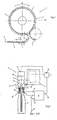
- the filling machine shown in FIG. 1 is one for a counter-pressure filling, for example for filling soft drinks, beer, mineral water u. Like. And consists essentially of a about a vertical machine axis in the direction of the arrow A rotating rotor 1, at the periphery of a plurality of filling points 2 is formed in the representation of FIG. 2 each of a filling element 3 and from a through a Lifting device up and down movable bottle carrier 4 exist. In Fig. 1, all filling points 2 between a bottle inlet and a bottle outlet of the filling machine, each with a plastic bottle (PET bottle) are shown occupied.
- PET bottle plastic bottle
- the bottles to be filled 5 are supplied to the filling machine via a feed dog 6, brought by means of a Einteilschnecke 7 or otherwise to the required machine spacing and passed over an inlet star 8 each a filling point of the rotor 1.
- the filled bottles 5 are removed from the filling points on an outlet star 9 and fed, for example, to a capper, not shown.
- Each filler has in the usual way, inter alia, in a housing 10 this Filling element formed liquid channel 11, which communicates with its one end via a flow meter 12 or otherwise with a part of the rotor 1 forming ring bowl 13 for the liquid product in combination.
- the liquid channel 11 forms a provided on the underside of the housing 10 discharge opening through which the liquid contents of the respective bottle 5 then flows when the liquid channel 11 also provided in the liquid valve 14 is opened.
- Each filling element 3 further has an actuating device 15 for controlling the liquid valve 14 or for controlling a valve body of this liquid valve.
- the actuating element 15 is preferably a pneumatic actuating element, which is controlled via an electromagnetic control valve 16 by a control device 17.
- each filling element 3 has, for example, a filling height-determining probe 18 which is designed, for example, as a conductivity probe and then delivers a probe signal, when filling a bottle 5, the mirror of the contents in the provided on the filling element 3 or there pressed bottle 5 a predetermined Height level has reached, in which the probe 18 is immersed in the liquid medium.
- the electronic control device 17 which is preferably a microprocessor-based device has in the illustrated embodiment a total of three inputs 19, 20 and 21, of which the input 19 to the signal output of the flow meter 12, the input 20 to the probe 18 and the input 21 at a parent, common to all filling stations of the filling machine electronic control (higher-level processor) is connected, as well as the control means 17 of the remaining filling 2 or filling elements 3.
- the control device 17 of each filling element 3 further has an output 23, via which each Filling element 3 individually associated control valve 16 is driven.
- each filling station 2 The operation of the filling machine or each filling station 2 can be described as follows: After the respective bottle 5 has been transferred from the inlet star 8 to a filling station 2, takes place in a predetermined angular range of rotation of the rotor 1 after a bias with its mouth 5 ' tight against the respective filling element 3 adjacent bottle 5 in the filling phase under counter pressure, first a volume filling the bottle 5 with the liquid contents, ie at the beginning of this filling phase, the liquid valve 14 is opened. The volume filling is then terminated by closing the liquid valve 14 when a predetermined volume of the liquid filling material has entered the bottle provided at the respective filling point 2.
- the volume charge is controlled based on the flow rate meter 12 supplied signal.
- This signal consists for example of a pulse train in which the number of pulses per unit time is a measure of the flow or volume of the liquid filling material, which has flowed through the flow meter 12 in the relevant unit of time.
- the control valve 17 controls the control valve 16 in such a way that thereby the closing of the liquid valve 14 takes place via the actuating element 15.
- the desired value for all filling stations 2 or their control devices 17 can be input jointly via the central controller 22, specifically via the signal line 24.
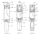
- the holding devices according to the invention are designed as the neck collar 25 of a bottle 5 supporting centering and attached to height-adjustable lifting rods 26.
- the lifting rods 26 are held in guides 27 of the filling element 3 and are urged by means of compression springs 28 with a guide roller 29 against a control cam 30, which causes a downward movement of the lifting elements by the adjacent guide roller 29.
- the bottles 5 are transferred to the centering surfaces.
- the bottles After taking over a supported bottle 5 and leaving the control cam area, the bottles reach the filling opening 31 of the filling element 3 and are tensioned against them only with the contact force of the springs 28. With the beginning of the filling process then begins the actual main pressing.
- FIGS. 3, 4 and 5 there is a piston / cylinder arrangement 32 above the filling opening 31 on the filling valve body.
- the cylinder chamber 33 formed as part of the filling valve 3 and as a pressure or inlet channel 34, 35 for the bottle to be filled 5 to be supplied and / or discharged from these pressure media, eg. As purge gas, biasing and clamping gas, inert gas, sterilization media and the like.
- the piston 36 is connected to the Hubrollenlagerung 37 or the carrier 38 and relative to the attached to the rotor Filling elements 3 movable.
- the optimum contact pressure for the bottle mouth 5 'against the outlet channel or the filling openings is always ensured.
- corresponding deflection or rinsing heads can be picked up by the holding devices, wherein the flushing medium or the rinsing pressure for pressing the rinsing heads is used.
- the piston 36 may also be designed as a correspondingly formed membrane.
Claims (7)
- Machine de remplissage pour des récipients, tels que des bouteilles, des boîtes, des cartons et autres récipients similaires, en particulier une machine de remplissage pour la mise en bouteille de liquides, comportant des dispositifs d'élévation disposés sur un rotor/carrousel pour le levage des récipients pour les placer contre les orifices de remplissage, les dispositifs d'élévation étant constitués de barres de levage déplaçables à la verticale, dans le sens contraire à l'effet de ressort, avec des dispositifs de retenue disposés sur la partie inférieure sous la forme d'outils de préhension, de surfaces d'appui et de centrage pour l'embouchure du récipient et/ou son col, caractérisée en ce que, au-dessus des orifices de remplissage, dans et/ou sur la soupape de remplissage (3), on a prévu un agencement piston/cylindre (32) déplaçant le dispositif d'élévation dans le sens de pression, agencement dont la chambre de cylindre (33) est réalisée sous la forme de canal de passage ou de canal d'entrée (34, 35) pour les fluides de pression, tels que du gaz de rinçage, du gaz de tension et du gaz de précontrainte, du gaz inerte, des fluides de stérilisation, à amener vers le récipient (5) à remplir et/ou à retirer de celui-ci.
- Machine de remplissage selon la revendication 1, caractérisée en ce que la chambre de cylindre (33) est disposée dans et/ou sur la soupape de remplissage/l'élément de soupape de remplissage (3) et le piston (36) est raccordé au logement à galets de levage (37) et/ou à son support (38).
- Machine de remplissage selon les revendications précédentes, caractérisée en ce que le piston (36) est disposé dans/ou sur l'élément de soupape de remplissage (3) et le carter de cylindre (33) est raccordé au logement à galets de levage (37) ou à son support (38).
- Machine de remplissage selon les revendications précédentes, caractérisée en ce que l'agencement piston/cylindre (32) est directement raccordé aux barres de levage (26) déplaçables à la verticale.
- Machine de remplissage selon les revendications précédentes, caractérisée en ce qu'un récipient de rinçage peut être pressé contre la partie inférieure de la soupape de remplissage au moyen des dispositifs de préhension, des surfaces d'appui et de centrage ou de pression pour le col de récipient (5').
- Machine de remplissage selon les revendications précédentes, caractérisée en ce que la conduite d'amenée pour un fluide de rinçage et/ou de stérilisation est raccordée ou raccordable à la chambre de cylindre.
- Machine de remplissage selon les revendications précédentes, caractérisée en ce que le piston (36) est réalisé sous la forme d'une membrane correspondant avec la chambre de cylindre (33).
Applications Claiming Priority (2)
| Application Number | Priority Date | Filing Date | Title |
|---|---|---|---|
| DE10346044 | 2003-10-02 | ||
| DE10346044.6A DE10346044B4 (de) | 2003-10-02 | 2003-10-02 | Behandlungsmaschine für Behälter wie Flaschen, Dosen und dgl. |
Publications (2)
| Publication Number | Publication Date |
|---|---|
| EP1520833A1 EP1520833A1 (fr) | 2005-04-06 |
| EP1520833B1 true EP1520833B1 (fr) | 2006-04-19 |
Family
ID=34306245
Family Applications (1)
| Application Number | Title | Priority Date | Filing Date |
|---|---|---|---|
| EP04020110A Active EP1520833B1 (fr) | 2003-10-02 | 2004-08-25 | Machine de remplissage |
Country Status (5)
| Country | Link |
|---|---|
| US (1) | US7311125B2 (fr) |
| EP (1) | EP1520833B1 (fr) |
| JP (1) | JP4459766B2 (fr) |
| CN (1) | CN1626434B (fr) |
| DE (2) | DE10346044B4 (fr) |
Cited By (4)
| Publication number | Priority date | Publication date | Assignee | Title |
|---|---|---|---|---|
| DE102010007288A1 (de) | 2010-02-08 | 2011-08-11 | KHS GmbH, 44143 | Verfahren sowie Füllsystem zum Füllen von Behältern, insbesondere zum Druckfüllen von Behältern |
| DE102013101813A1 (de) | 2013-02-25 | 2014-08-28 | Khs Gmbh | Füllsystem |
| WO2014127879A1 (fr) | 2013-02-25 | 2014-08-28 | Khs Gmbh | Système de remplissage |
| DE102014104874A1 (de) * | 2014-04-04 | 2015-10-08 | Krones Ag | Vorrichtung und Verfahren zur Herstellung einer Kunststoffflasche und deren Befüllung mit einem Füllprodukt |
Families Citing this family (36)
| Publication number | Priority date | Publication date | Assignee | Title |
|---|---|---|---|---|
| US10214312B2 (en) | 2006-03-06 | 2019-02-26 | Plastipak Packaging, Inc. | Lightweight plastic container and preform |
| US8857637B2 (en) | 2006-03-06 | 2014-10-14 | Plastipak Packaging, Inc. | Lightweight plastic container and preform |
| EP1860057B1 (fr) * | 2006-05-24 | 2009-05-06 | Sidel Holdings & Technology S.A. | Tête de remplissage avec interrupteur de niveau dans un conduit isolé |
| US7963302B2 (en) * | 2006-09-26 | 2011-06-21 | Emhart Glass S.A. | Machine for testing container capacity |
| DE102008023776A1 (de) * | 2008-05-15 | 2009-11-26 | Khs Ag | Behandlungsmaschine für Flaschen oder dergleichen Behälter |
| DE102009033809A1 (de) | 2009-07-18 | 2011-01-20 | Krones Ag | Vorrichtung zum Behandeln von Behältnissen mit Trägersterilisation |
| CN102152254A (zh) * | 2011-02-25 | 2011-08-17 | 江苏速升自动化装备系统工程有限公司 | 连杆提升工具 |
| US8291948B1 (en) * | 2012-03-16 | 2012-10-23 | Marks George H | Centering guide for automated bottling machinery |
| DE102012008755A1 (de) * | 2012-05-04 | 2013-11-07 | Khs Gmbh | Hubvorrichtung für Behälterbehandlungsmaschinen, Behälterbehandlungsmaschine mit einer solchen Hubvorrichtung sowie Verfahren zum Füllen von Behältern |
| CN103058117A (zh) * | 2013-01-10 | 2013-04-24 | 江苏新美星包装机械股份有限公司 | 瓶提升和灌装一体式的阀体 |
| JP6158596B2 (ja) * | 2013-05-31 | 2017-07-05 | シブヤマシナリー株式会社 | 充填装置 |
| DE102013106927A1 (de) * | 2013-07-02 | 2015-01-08 | Khs Gmbh | Füllelement sowie Füllmaschine |
| DE102013113070B3 (de) * | 2013-11-26 | 2015-03-19 | Khs Gmbh | Füllelement sowie Füllmaschine |
| DE102014102960A1 (de) * | 2014-03-06 | 2015-09-10 | Krones Ag | Vorrichtung zum Befüllen eines Behälters mit einem Füllprodukt |
| US10287152B2 (en) | 2014-12-30 | 2019-05-14 | Gea Procomac S.P.A. | Apparatus and method for filling containers |
| CN105036030B (zh) * | 2015-08-12 | 2017-05-24 | 广州达意隆包装机械股份有限公司 | 灌装机的瓶升降装置 |
| CN105460872B (zh) * | 2016-01-04 | 2019-06-04 | 江苏新美星包装机械股份有限公司 | 一种灌装瓶升降机构 |
| CA3030344C (fr) * | 2016-07-11 | 2023-09-19 | William P. Young Company | Element de prehension de goulot comportant un verrouillage |
| US9643746B1 (en) | 2016-09-20 | 2017-05-09 | Paul E. Lunn | System and method of transferring matter through a sealed container |
| DE102017105482A1 (de) * | 2017-03-15 | 2018-09-20 | Khs Gmbh | Behälterbehandlungsvorrichtung |
| TWI618514B (zh) * | 2017-05-17 | 2018-03-21 | 弘麒科技股份有限公司 | 氣泡水機及攜帶式壓力瓶 |
| CN107031899A (zh) * | 2017-05-19 | 2017-08-11 | 连云港福润食品有限公司 | 灌装管肉泥回收装置 |
| CN108688879B (zh) * | 2018-02-17 | 2023-11-24 | 中科(洛阳)机器人与智能装备研究院 | 智能型食品包装设备用柔性循环输送装置 |
| CN111867967A (zh) * | 2018-03-12 | 2020-10-30 | 埃巴尔新方案有限公司 | 反压力饮料分配器和使用方法 |
| CN108529529A (zh) * | 2018-05-11 | 2018-09-14 | 合肥中辰轻工机械有限公司 | 一种灌装机短行程pet瓶抬升装置 |
| DE102019114422A1 (de) * | 2019-05-29 | 2020-12-03 | Krones Aktiengesellschaft | Füllmaschine und Verfahren zum Abfüllen eines flüssigen Produkts in Flaschen |
| EP4114553A1 (fr) * | 2020-03-05 | 2023-01-11 | Sodaking IPV Pty Ltd | Appareil de carbonatation de boisson à la demande |
| WO2021174314A1 (fr) * | 2020-03-05 | 2021-09-10 | Sodaking IPV Pty Ltd | Appareil de gazéification de boisson à la demande |
| JP2023516773A (ja) * | 2020-03-05 | 2023-04-20 | ソーダキング アイピーブイ ピーティーワイ リミテッド | 飲料炭酸化装置 |
| US11434125B2 (en) * | 2020-06-05 | 2022-09-06 | WhidBrew Technologies, Inc | Automated beverage pouring device with foam control |
| IT202000013465A1 (it) * | 2020-06-05 | 2021-12-05 | Kosme Srl Unipersonale | Macchina per riempire contenitori di due tipologie differenti con una sostanza liquida, in particolare con una bevanda |
| CN112357870B (zh) * | 2020-11-10 | 2022-05-31 | 德清三盛氟塑科技有限公司 | 一种液体饮料灌装阀门 |
| CN113307208B (zh) * | 2021-06-08 | 2023-03-24 | 上海拓达机电设备有限公司 | 一种高速灌装机 |
| CN114261937B (zh) * | 2022-03-03 | 2022-05-10 | 东营大地硅业有限公司 | 一种化工液体定量灌装设备 |
| DE102022118287A1 (de) | 2022-07-21 | 2024-02-01 | Krones Aktiengesellschaft | Dosenfüllvorrichtung und Verfahren zum Füllen von Dosen |
| CN115651569A (zh) * | 2022-09-30 | 2023-01-31 | 芜湖徽氏新材料科技有限公司 | 一种绝缘胶水及其灌装设备 |
Family Cites Families (17)
| Publication number | Priority date | Publication date | Assignee | Title |
|---|---|---|---|---|
| US3172436A (en) * | 1963-01-23 | 1965-03-09 | Horix Mfg Company | Volumetric filling apparatus |
| US3386480A (en) * | 1965-11-12 | 1968-06-04 | Cons Packaging Machinery Corp | Filling machine with adjustable fill height control |
| IT1180863B (it) * | 1984-03-02 | 1987-09-23 | Saromi Spa | Dispositivo di aggancio di un contenitore ad una valvola di riempiemento in particolare per macchine automatiche di tipo continuo per il riempiemento di bottiglie con liquidi |
| IT1214901B (it) * | 1985-11-11 | 1990-01-31 | Simonazzi Spa A & L | Riempitrice rotativa continua equipaggiata,per il sollevamento meccanico delle bottiglie vuote eper l'abbassamento libero delle bottiglie riempite,soltanto con con punterie prensili munite di chiavistello di bloccaggio sincronizzato col processo diriempimento |
| DE3732882C1 (de) * | 1987-09-30 | 1988-07-07 | Orthmann & Herbst | Behaelterhubanordnung fuer Getraenkefuelleinrichtungen |
| US5219405A (en) * | 1987-12-16 | 1993-06-15 | Krones Ag Hermann Kronseder Maschinenfabrik | Continuously operating rotational bottle filling installation |
| DE3830663C2 (de) * | 1988-09-09 | 1994-08-11 | Orthmann & Herbst | Füllorgan für karbonisierte Getränke mit Behälteranpreßeinrichtung |
| DE9017262U1 (fr) * | 1990-12-21 | 1991-03-28 | Krones Ag Hermann Kronseder Maschinenfabrik, 8402 Neutraubling, De | |
| DE4133713A1 (de) * | 1991-10-11 | 1993-04-15 | Kronseder Maschf Krones | Verfahren und vorrichtung zur fuellung eines gefaesses mit einer fluessigkeit |
| DE9301420U1 (de) * | 1993-02-02 | 1994-03-03 | Kronseder Maschf Krones | Füllmaschine für Gefäße |
| DE4338669A1 (de) * | 1993-11-12 | 1995-05-18 | Khs Masch & Anlagenbau Ag | Füllelement für Füllmaschinen zum Abfüllen eines flüssigen Füllgutes in Flaschen oder dergleichen Behälter |
| DE4309429A1 (de) * | 1993-03-24 | 1994-09-29 | Khs Masch & Anlagenbau Ag | Füllmaschine |
| US5896898A (en) * | 1993-04-05 | 1999-04-27 | Diversey Lever, Inc. | Dispenser |
| DE19545080A1 (de) * | 1995-12-04 | 1997-06-05 | Khs Masch & Anlagenbau Ag | Vorrichtung zum Anpressen von Gefäßen an Gefäßfüllmaschinen |
| CN2373432Y (zh) * | 1998-08-21 | 2000-04-12 | 中国轻工业机械总公司南京轻工业机械厂 | 流体电子灌装阀的机械结构 |
| DE29817145U1 (de) * | 1998-09-24 | 1999-04-29 | Krones Ag | Gefäßbehandlungsmaschine mit einem Rotor |
| CN2511604Y (zh) * | 2001-12-03 | 2002-09-18 | 介鸿机械股份有限公司 | 改进的瓶装饮料的填充装置 |
-
2003
- 2003-10-02 DE DE10346044.6A patent/DE10346044B4/de not_active Expired - Lifetime
-
2004
- 2004-08-25 DE DE502004000438T patent/DE502004000438D1/de active Active
- 2004-08-25 EP EP04020110A patent/EP1520833B1/fr active Active
- 2004-09-16 JP JP2004269816A patent/JP4459766B2/ja active Active
- 2004-09-29 US US10/952,706 patent/US7311125B2/en active Active
- 2004-09-30 CN CN200410085590.9A patent/CN1626434B/zh active Active
Cited By (5)
| Publication number | Priority date | Publication date | Assignee | Title |
|---|---|---|---|---|
| DE102010007288A1 (de) | 2010-02-08 | 2011-08-11 | KHS GmbH, 44143 | Verfahren sowie Füllsystem zum Füllen von Behältern, insbesondere zum Druckfüllen von Behältern |
| WO2011095187A1 (fr) | 2010-02-08 | 2011-08-11 | Khs Gmbh | Procédé et système de remplissage pour le remplissage sous pression de récipients |
| DE102013101813A1 (de) | 2013-02-25 | 2014-08-28 | Khs Gmbh | Füllsystem |
| WO2014127879A1 (fr) | 2013-02-25 | 2014-08-28 | Khs Gmbh | Système de remplissage |
| DE102014104874A1 (de) * | 2014-04-04 | 2015-10-08 | Krones Ag | Vorrichtung und Verfahren zur Herstellung einer Kunststoffflasche und deren Befüllung mit einem Füllprodukt |
Also Published As
| Publication number | Publication date |
|---|---|
| DE502004000438D1 (de) | 2006-05-24 |
| CN1626434A (zh) | 2005-06-15 |
| US20050092390A1 (en) | 2005-05-05 |
| JP2005112469A (ja) | 2005-04-28 |
| CN1626434B (zh) | 2014-03-12 |
| US7311125B2 (en) | 2007-12-25 |
| DE10346044B4 (de) | 2016-04-28 |
| DE10346044A1 (de) | 2005-04-21 |
| JP4459766B2 (ja) | 2010-04-28 |
| EP1520833A1 (fr) | 2005-04-06 |
Similar Documents
| Publication | Publication Date | Title |
|---|---|---|
| EP1520833B1 (fr) | Machine de remplissage | |
| EP1692071B1 (fr) | Element de remplissage pour machine de remplissage et machine de remplissage equipee d'elements de remplissage de ce type | |
| EP2598429B1 (fr) | Machine de remplissage | |
| EP2138446B1 (fr) | Système de remplissage à rayon libre | |
| EP2132130B1 (fr) | Système de remplissage | |
| EP2146922B1 (fr) | Dispositif de remplissage et procédé pour commander un dispositif de remplissage | |
| EP2019809B1 (fr) | Procédé et dispositif de moussage commandé d'un produit mis en bouteilles ou dans des contenants similaires | |
| EP0515960B1 (fr) | Procédé et dispositif pour remplir des bouteilles, des boîtes ou des récipients similaires | |
| DE102011111483A1 (de) | Behälterbehandlungsmaschine | |
| DE10011653A1 (de) | Aufschäumvorrichtung | |
| DE3506250C2 (fr) | ||
| EP2915772B1 (fr) | Dispositif de remplissage d'un récipient avec un produit de remplissage | |
| EP1544157B1 (fr) | Machine de remplissage pour remplir des récipients | |
| EP1655264A2 (fr) | Machine de remplissage du type à carrousel | |
| DE4030081A1 (de) | Aufschaeumvorrichtung zum verdraengen des restluftvolumens aus mit einem aufschaeumbaren fluessigen fuellgut gefuellten behaeltern, insbesondere flaschen | |
| DE20315253U1 (de) | Behandlungsmaschine für Behälter wie Flaschen, Dosen u.dgl. | |
| WO2016008707A1 (fr) | Système de remplissage et procédé pour faire fonctionner un tel système de remplissage | |
| DE3638601A1 (de) | Aufschaeumvorrichtung zum verdraengen des restluftvolumens aus mit einem aufschaeumbaren fluessigen fuellgut gefuellten behaeltern, insbesondere flaschen | |
| DE102015224973A1 (de) | Behälterbehandlungsmaschine | |
| EP2788273B1 (fr) | Machine de remplissage | |
| DE20319619U1 (de) | Füllmaschine zum Füllen von Behältern | |
| DE19545080A1 (de) | Vorrichtung zum Anpressen von Gefäßen an Gefäßfüllmaschinen | |
| DE19941456C1 (de) | Füllmaschine mit vakuumbeaufschlagbaren Füllorganen | |
| EP2065335B1 (fr) | Procédé destiné au remplissage de récipients | |
| DE102010007288A1 (de) | Verfahren sowie Füllsystem zum Füllen von Behältern, insbesondere zum Druckfüllen von Behältern |
Legal Events
| Date | Code | Title | Description |
|---|---|---|---|
| PUAI | Public reference made under article 153(3) epc to a published international application that has entered the european phase |
Free format text: ORIGINAL CODE: 0009012 |
|
| AK | Designated contracting states |
Kind code of ref document: A1 Designated state(s): AT BE BG CH CY CZ DE DK EE ES FI FR GB GR HU IE IT LI LU MC NL PL PT RO SE SI SK TR |
|
| AX | Request for extension of the european patent |
Extension state: AL HR LT LV MK |
|
| 17P | Request for examination filed |
Effective date: 20050423 |
|
| GRAP | Despatch of communication of intention to grant a patent |
Free format text: ORIGINAL CODE: EPIDOSNIGR1 |
|
| GRAS | Grant fee paid |
Free format text: ORIGINAL CODE: EPIDOSNIGR3 |
|
| RTI1 | Title (correction) |
Free format text: FILLING MACHINE |
|
| AKX | Designation fees paid |
Designated state(s): DE FR GB IT NL |
|
| GRAA | (expected) grant |
Free format text: ORIGINAL CODE: 0009210 |
|
| AK | Designated contracting states |
Kind code of ref document: B1 Designated state(s): DE FR GB IT NL |
|
| REG | Reference to a national code |
Ref country code: GB Ref legal event code: FG4D Free format text: NOT ENGLISH |
|
| RAP2 | Party data changed (patent owner data changed or rights of a patent transferred) |
Owner name: KHS AG |
|
| REF | Corresponds to: |
Ref document number: 502004000438 Country of ref document: DE Date of ref document: 20060524 Kind code of ref document: P |
|
| NLT2 | Nl: modifications (of names), taken from the european patent patent bulletin |
Owner name: KHS AG Effective date: 20060426 |
|
| GBT | Gb: translation of ep patent filed (gb section 77(6)(a)/1977) |
Effective date: 20060628 |
|
| ET | Fr: translation filed | ||
| PLBE | No opposition filed within time limit |
Free format text: ORIGINAL CODE: 0009261 |
|
| STAA | Information on the status of an ep patent application or granted ep patent |
Free format text: STATUS: NO OPPOSITION FILED WITHIN TIME LIMIT |
|
| 26N | No opposition filed |
Effective date: 20070122 |
|
| REG | Reference to a national code |
Ref country code: NL Ref legal event code: TD Effective date: 20111114 |
|
| REG | Reference to a national code |
Ref country code: FR Ref legal event code: CD Owner name: KHS GMBH Effective date: 20111122 Ref country code: FR Ref legal event code: CD Owner name: KHS GMBH Effective date: 20111121 |
|
| REG | Reference to a national code |
Ref country code: FR Ref legal event code: PLFP Year of fee payment: 13 |
|
| REG | Reference to a national code |
Ref country code: FR Ref legal event code: PLFP Year of fee payment: 14 |
|
| REG | Reference to a national code |
Ref country code: FR Ref legal event code: PLFP Year of fee payment: 15 |
|
| PGFP | Annual fee paid to national office [announced via postgrant information from national office to epo] |
Ref country code: GB Payment date: 20220823 Year of fee payment: 19 |
|
| PGFP | Annual fee paid to national office [announced via postgrant information from national office to epo] |
Ref country code: NL Payment date: 20230821 Year of fee payment: 20 |
|
| PGFP | Annual fee paid to national office [announced via postgrant information from national office to epo] |
Ref country code: IT Payment date: 20230825 Year of fee payment: 20 |
|
| PGFP | Annual fee paid to national office [announced via postgrant information from national office to epo] |
Ref country code: FR Payment date: 20230822 Year of fee payment: 20 Ref country code: DE Payment date: 20230821 Year of fee payment: 20 |
|
| GBPC | Gb: european patent ceased through non-payment of renewal fee |
Effective date: 20230825 |