EP1518674A1 - Rotationskörper einer Arbeitsmaschine - Google Patents
Rotationskörper einer Arbeitsmaschine Download PDFInfo
- Publication number
- EP1518674A1 EP1518674A1 EP03103567A EP03103567A EP1518674A1 EP 1518674 A1 EP1518674 A1 EP 1518674A1 EP 03103567 A EP03103567 A EP 03103567A EP 03103567 A EP03103567 A EP 03103567A EP 1518674 A1 EP1518674 A1 EP 1518674A1
- Authority
- EP
- European Patent Office
- Prior art keywords
- roller
- rotary body
- shaft
- pin
- outer body
- Prior art date
- Legal status (The legal status is an assumption and is not a legal conclusion. Google has not performed a legal analysis and makes no representation as to the accuracy of the status listed.)
- Granted
Links
- 239000004033 plastic Substances 0.000 claims description 25
- 239000002184 metal Substances 0.000 abstract description 5
- OKTJSMMVPCPJKN-UHFFFAOYSA-N Carbon Chemical compound [C] OKTJSMMVPCPJKN-UHFFFAOYSA-N 0.000 abstract 1
- 229910052799 carbon Inorganic materials 0.000 abstract 1
- 239000000835 fiber Substances 0.000 abstract 1
- 241000446313 Lamella Species 0.000 description 4
- 239000007787 solid Substances 0.000 description 4
- 238000005452 bending Methods 0.000 description 3
- 238000000576 coating method Methods 0.000 description 3
- 238000005096 rolling process Methods 0.000 description 3
- 239000004918 carbon fiber reinforced polymer Substances 0.000 description 2
- 239000011248 coating agent Substances 0.000 description 2
- 238000004519 manufacturing process Methods 0.000 description 2
- 239000000463 material Substances 0.000 description 2
- 238000000926 separation method Methods 0.000 description 2
- 230000015572 biosynthetic process Effects 0.000 description 1
- 230000000694 effects Effects 0.000 description 1
- 239000007788 liquid Substances 0.000 description 1
- 239000003973 paint Substances 0.000 description 1
- 239000000126 substance Substances 0.000 description 1
- 230000003319 supportive effect Effects 0.000 description 1
Images

Classifications
-
- B—PERFORMING OPERATIONS; TRANSPORTING
- B65—CONVEYING; PACKING; STORING; HANDLING THIN OR FILAMENTARY MATERIAL
- B65H—HANDLING THIN OR FILAMENTARY MATERIAL, e.g. SHEETS, WEBS, CABLES
- B65H27/00—Special constructions, e.g. surface features, of feed or guide rollers for webs
-
- B—PERFORMING OPERATIONS; TRANSPORTING
- B41—PRINTING; LINING MACHINES; TYPEWRITERS; STAMPS
- B41F—PRINTING MACHINES OR PRESSES
- B41F13/00—Common details of rotary presses or machines
- B41F13/08—Cylinders
-
- B—PERFORMING OPERATIONS; TRANSPORTING
- B41—PRINTING; LINING MACHINES; TYPEWRITERS; STAMPS
- B41F—PRINTING MACHINES OR PRESSES
- B41F31/00—Inking arrangements or devices
- B41F31/26—Construction of inking rollers
-
- B—PERFORMING OPERATIONS; TRANSPORTING
- B41—PRINTING; LINING MACHINES; TYPEWRITERS; STAMPS
- B41F—PRINTING MACHINES OR PRESSES
- B41F7/00—Rotary lithographic machines
- B41F7/20—Details
- B41F7/24—Damping devices
- B41F7/26—Damping devices using transfer rollers
-
- B—PERFORMING OPERATIONS; TRANSPORTING
- B65—CONVEYING; PACKING; STORING; HANDLING THIN OR FILAMENTARY MATERIAL
- B65H—HANDLING THIN OR FILAMENTARY MATERIAL, e.g. SHEETS, WEBS, CABLES
- B65H2404/00—Parts for transporting or guiding the handled material
- B65H2404/10—Rollers
- B65H2404/13—Details of longitudinal profile
- B65H2404/134—Axle
- B65H2404/1342—Built-up, i.e. arrangement for mounting axle element on roller body
- B65H2404/13421—Built-up, i.e. arrangement for mounting axle element on roller body involving two elements, i.e. an element at each end of roller body
-
- B—PERFORMING OPERATIONS; TRANSPORTING
- B65—CONVEYING; PACKING; STORING; HANDLING THIN OR FILAMENTARY MATERIAL
- B65H—HANDLING THIN OR FILAMENTARY MATERIAL, e.g. SHEETS, WEBS, CABLES
- B65H2404/00—Parts for transporting or guiding the handled material
- B65H2404/10—Rollers
- B65H2404/13—Details of longitudinal profile
- B65H2404/135—Body
- B65H2404/1351—Pipe element
-
- B—PERFORMING OPERATIONS; TRANSPORTING
- B65—CONVEYING; PACKING; STORING; HANDLING THIN OR FILAMENTARY MATERIAL
- B65H—HANDLING THIN OR FILAMENTARY MATERIAL, e.g. SHEETS, WEBS, CABLES
- B65H2404/00—Parts for transporting or guiding the handled material
- B65H2404/50—Surface of the elements in contact with the forwarded or guided material
- B65H2404/56—Flexible surface
- B65H2404/563—Elastic, supple built-up surface
Definitions
- the invention relates to a rotary body of a working machine, in particular a Roller of a printing machine, according to the preamble of claim 1, 3, 6 and 10 respectively.
- EP 0 544 374 B1 discloses a roller with a cylindrical outer body Plastic and an internal plastic shaft known, the end portions the inner shaft each have metal sheaths, which are up to extend the respective shaft end.
- a roller lock for a roller of a printing machine is with at least one of this roller associated actuator for the input and / or the Anund Turn off the roller to another unit known.
- DE 25 28 008 A1 shows a printing machine with rollers or cylinders, which a Have width for printing six juxtaposed newspaper pages.
- the invention is based on the object, a rotating body of a working machine, in particular, a roller of a printing machine to create.
- the achievable with the present invention consist in particular that with simple means a stable and low-wear design of a rotating body is created. This has a reduced due to its low weight Deflection in its longitudinal extent and is still stored wear.
- it has at least one actuator, by means of which he independent of adjusting movements of adjacent units on their own adjust and / or is switched on or off.
- the roller has a length of its effective lateral surface, which corresponds to at least six widths of a printed page, in particular newspaper page,
- the roller has e.g. a non-metallic shell, e.g. B. plastic, in particular from CFK, on, which in the region of the ends on metallic pins, in particular Full body, rotatably mounted.
- a non-metallic shell e.g. B. plastic, in particular from CFK, on, which in the region of the ends on metallic pins, in particular Full body, rotatably mounted.
- the two frontally arranged metallic pins can in an advantageous Execution be connected to each other by an internal shaft.
- the inside lying wave may be made of metal, but advantageously of plastic, in particular CFRP, be executed.
- the bearing of the roller in an area of the pin advantageous, which viewed axially outside of the Pin connecting plastic shaft is located.
- the metallic pins in this area advantageously designed as a solid body, which either in the Intervene plastic shaft or engage around this outside of the storage area.
- the rotation body is a single, i. individually dosed, places as well as a wave for Stiffening - especially made of plastic - an advantage.
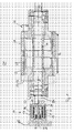
- a rotary body 01 of a working machine in particular a cylinder 01 or a Roller 01 of a printing press, has a cylindrical outer body 02, which in Range of its ends over stock 03, z. B. radial bearings, in particular rolling bearings, in the Operation gestell- and rotationally fixed pin 04 in a frame 05 of the machine is stored.
- the frame 05 and a fastening device described in more detail below are not shown in Fig. 1 and 2, but preferably provided in the same way.
- the outer body 02 has at least in one area of its usable bale length L a shell 06 with an annular profile.
- Under usable length L becomes here one Length of the bale or the lateral surface of the outer body 02 understood, which for Transfer of liquids such as paint or dampening solution or for the management of sheet material is suitable, d. H. a contact surface to a machined Substance or a cooperating aggregate forms. In the inking unit this is the color or Dampening solution provided length of the roller 01, in the range of Printing cylinders the width to be printed.
- the shell 06 is at least through a layer 07, z. B. plastic layer 07, z. B. a Plastic tube, for example made of CFRP formed. She can be on her outside directed surface advantageously a coating 08, z. B. an elastic layer, exhibit.
- the plastic pipe is designed carrying load, d. H. she wears - in Difference for example to sleeves or other thin-walled carrier layers or coatings - essential for absorbing bending, shear and / or thrust at.
- the rotation body 01 concentric with its outer body 02 an internal, central shaft 09, z. B. hollow shaft 09 on which the two pins 04 connects together.
- the illustrated advantageous embodiment which is the Pin 04 connecting shaft 09, however, made of plastic (plastic shaft 09), For example, made of CFK.
- the plastic shaft 09 is accordingly load carrying over the free length, d. H. she takes without any more metallic Support in this area bending, shear and / or thrust on.
- the pins 04 However, both in the embodiment of FIG. 1 and FIG.
- the metallic pins 04 are in this storage area as a solid body executed.
- the pin 04 or a part of a multi-part pin 09 engages in a first Execution with a frame distal end in the plastic shaft (Fig. 1). This is the connection between the shaft 09 and the pin 04 in one of the storage area between outer body 02 and pin 04 different area.
- a second embodiment engages around in his frame remote end with a Recess 11 provided pin 04 the end of the shaft 09.
- the bearing and the Connection are again spatially separated.
- a wide area of the outer body 02 is made Fig. 2 executed without additional metallic support.
- the plastic layer 07 is Accordingly, load carrying carried out over the free length, d. H. she takes in the essentially alone in this area the bending, shear and / or thrust on.
- Material and wall thickness d07 are chosen so that at a load of about 10 N / cm (as Line force evenly applied over the bale length L) a deflection of maximum 0.2 mm results.
- the wall thickness d07 of the layer formed as CFK pipe 07 is advantageous for the at least 6 printed pages width roller 01 at 5 to 15 mm, in particular 6 to 12 mm.
- the bearing 03 corresponding to a bearing ring Diameter between shell 06 and pin 04 may be arranged or - like shown - can connect a hub 12, the shell 06 with the bearing 03.
- the hub 12 is preferably metallic.
- the hub 12 is also part of a body 13, here roller or cylinder body 13, which on the entire effective Length L of the body of revolution 01 tubular supports the shell 06.
- the execution of the outer body 02 with main body 13 is on the remaining embodiment of the rotary body 01 of FIG. 2nd applicable, as well as the embodiment without body 13 of FIG. 2 on the execution according to FIG. 1.
- the pins 04 are designed in stages and / or in several parts. In principle, they can be made in one or more parts, in stages or purely cylindrical.
- the rotary body 01 is preferably as a slender cylinder 01 or slender roller 01 with a ratio of usable length L to diameter D of z. B. 10 to 14, in particular 11 to 13 executed.
- the usable or effective length L of Rotation body 01 is between 1,850 mm and 2,400 mm, preferably between 1,950 and 2,250 mm. It preferably has at least one length L, which six Widths of a printed page, in particular widths of a newspaper page corresponds. Of the Diameter D is z. B. between 115 and 170 mm, in particular from 125 to 160 mm.
- the pins 04 of the rotating body 01 are preferably in fastening devices 14, z. B. bearings, each frontally connected to the frame 05.
- the mentioned embodiments of the rotating body 01 is in an advantageous embodiment for On and / or turning on and off at least assigned a separate actuator 16, by means of which he independent of positioning movements of adjacent units and / or Rotary bodies on their own adjust and / or on or off.
- the actuator 16 can basically be used in different ways, e.g. as electromotive, magnetic, pneumatically or hydraulically acting adjusting means to be executed, which in a Direction perpendicular to the axis of rotation of the rotating body 01 acts and the pin 04 or the fastening device 14 in the plane perpendicular to the axis of rotation can move relative to the frame 05 and fix if necessary.
- Preferably to both End sides of the rotating body 01 each provided an actuator 14 on the frame 05.
- the fastening device 14 includes the Actuator 16.
- the roller 01 can with its pin 04 releasably connected to one of the Fastening device 14 provided quick release fastened.
- Quick locks or roller locks are known from the prior art and have z.
- B a semicircular lower and not shown releasable upper Bearing shell on.
- the attachment device 14 is essentially one of essentially one sleeve-shaped frame holder 17 and a roller holder 18 constructed relatively to each other in a plane that extends perpendicular to the plane, can be moved against each other.
- the frame holder 17 may, for example by means of a pivot arm pivotally attached to the frame 05 of a printing press become.
- Roller holder 18 is in the basic position a circular cylindrical gap 19 with a Slit width of, for example, 1 mm to 10 mm, preferably 2 mm formed.
- At least one Actuator 16 is arranged. Distributed over the circumference are preferably total at least three, z. B. four trained for example in the form of pressure hoses Actuators 16, of which only two are shown in section in FIGS. 1 and 2, arranged. About unillustrated leads can from the wall of the actuators 16 pressure chambers are pressurized.
- slat elements 21 attached to the frame holder 17th fastened lamellar elements 22 meshing to form a lamella packet are arranged.
- a cross-sectionally T-shaped Stamp 23 is provided, the circular punch head 24 z. B. with a annular flange on the outermost lamellar element 21 and 22 of the Lamella packages comes to the plant.
- a pressure plate 25 attached to the spring force of a in the manner of a Disc spring pack 26 formed spring element 26 acts.
- the spring element 26 is biased between the pressure plate 25 and the frame holder 17 mounted so that the from the fin elements 21; 22 formed disc pack by the spring force, the from the punch 23 on the lamellar elements 21; 22 is jammed.
- a rolling bearing 03 is not between the outer body 02 in this case and the pin 04, but between the pin 04 and the fastening device or the frame 05 arranged.
- the depository for the Radial bearing 03 not in the range of the connection of shaft 09 and pin 04, but in a different area is arranged.
- the pin 04 is at least in this storage area advantageously designed as a solid body.
Landscapes
- Engineering & Computer Science (AREA)
- Mechanical Engineering (AREA)
- Rolls And Other Rotary Bodies (AREA)
- Inking, Control Or Cleaning Of Printing Machines (AREA)
- Rotary Presses (AREA)
Abstract
Description
- 01
- Rotationskörper, Walze, Zylinder
- 02
- Außenkörper
- 03
- Lager, Rotationslager
- 04
- Zapfen
- 05
- Gestell
- 06
- Hülle
- 07
- Schicht, Kunststoffschicht
- 08
- Beschichtung
- 09
- Welle, Hohlwelle, Kunststoffwelle
- 10
- -
- 11
- Ausnehmung
- 12
- Nabe
- 13
- Grundkörper, Walzen- bzw. Zylindergrundkörper
- 14
- Befestigungsvorrichtung
- 15
- -
- 16
- Aktuator
- 17
- Rahmenhalter
- 18
- Walzenhalter
- 19
- Spalt
- 20
- -
- 21
- Lamellenelement
- 22
- Lamellenelement
- 23
- Stempel
- 24
- Stempelkopf
- 25
- Druckplatte
- 26
- Federelement, Tellerfederpaket
- 27
- Druckanschluss
- 28
- Druckkammer
- d13
- Stärke
- d07
- Wandstärke
- D
- Durchmesser
- L
- Länge, Ballenlänge, wirksame, nutzbare
Claims (21)
- Rotationskörper einer Arbeitsmaschine mit einem zylindrischen Außenkörper (02) und einer im Außenkörper (02) konzentrisch angeordneten zentralen Welle (09), wobei die Welle (09) und zumindest eine tragende Schicht (07) einer Hülle (06) des Außenkörpers (02) aus Kunststoff ausgebildet sind, dadurch gekennzeichnet, dass in stirnseitige Enden der als Hohlwelle (09) ausgebildeten Welle (09) jeweils ein metallischer Zapfen (04) eingreift.
- Rotationskörper nach Anspruch 1, dadurch gekennzeichnet, dass stirnseitig jeweils ein metallischer Zapfen (04) mit der zentralen Welle (09) und dem Außenkörper (02) in der Weise verbunden ist, dass eine Lagerstelle eines Radiallagers (03) und einer Verbindung zwischen Zapfen (04) und Welle (09) in voneinander verschiedenen Bereichen des Zapfens (04) liegen.
- Rotationskörper einer Arbeitsmaschine mit einem zylindrischen Außenkörper (02) und einer im Außenkörper (02) konzentrisch angeordneten zentralen Welle (09), dadurch gekennzeichnet, dass stirnseitig jeweils ein metallischer Zapfen (04) mit der zentralen Welle (09) und dem Außenkörper (02) in der Weise verbunden ist, dass eine Lagerstelle eines Radiallagers (03) und einer Verbindung zwischen Zapfen (04) und Welle (09) in voneinander verschiedenen Bereichen des Zapfens (04) liegen.
- Rotationskörper nach Anspruch 2 oder 3, dadurch gekennzeichnet, dass das Radiallager (03) zwischen rotierbarem Außenkörper (02) und drehfestem Zapfen (04) angeordnet ist.
- Rotationskörper nach Anspruch 2 oder 3, dadurch gekennzeichnet, dass Außenkörper (02) und Zapfen (04) drehfest miteinander verbunden sind und das Radiallager (03) zwischen dem Zapfen (04) und einer bezüglich einer Drehbewegung gestellfesten Befestigungsvorrichtung (14) angeordnet ist.
- Rotationskörper einer Arbeitsmaschine mit einem zylindrischen Außenkörper (02), welcher eine Hülle (06) mit zumindest einer Schicht (07) aus Kunststoff aufweist, dadurch gekennzeichnet, dass der Außenkörper (02) einen metallischen, als Hohlkörper ausgeführten Grundkörper (13) aufweist, welcher auf einer gesamten wirksamen Länge (L) des Rotationskörpers (01) die Hülle (06) unterstützt.
- Rotationskörper nach Anspruch 1, 3 oder 6, dadurch gekennzeichnet, dass die wirksame Länge (L) auf seiner Mantelfläche mindestens sechs Breiten einer Druckseite, insbesondere Zeitungsseite, beträgt.
- Rotationskörper nach Anspruch 6, dadurch gekennzeichnet, dass der Rotationskörper eine im Außenkörper (02) konzentrisch angeordnete zentrale Welle (09) aufweist.
- Walze eines Farb- oder Feuchtwerks einer Druckmaschine, welche eine wirksame Länge (L) auf ihrer Mantelfläche von mindestens sechs Breiten einer Druckseite aufweist, dadurch gekennzeichnet, dass zumindest eine Last tragende Schicht (07) eines Außenkörpers (02) und/oder eine Last tragende, konzentrisch zum Außenkörper (02) angeordnete Welle (09) aus Kunststoff ausgebildet ist.
- Walze nach Anspruch 9, dadurch gekennzeichnet, dass die Walze (01) einen Außenkörper (02) sowie eine zentrale Welle (09) aufweist
- Rotationskörper nach Anspruch 1, 3, 6 oder Walze nach 9, dadurch gekennzeichnet, dass dem Rotationskörper (01) bzw. der Walze (01) zu dessen An- bzw. Abstellung und/oder Einstellung im Hinblick auf ein benachbartes Aggregat mindestens ein eigener, lediglich diesem Rotationskörper bzw. dieser Walze (01) zugeordneter Aktuator (16) zugeordnet ist.
- Rotationskörper nach Anspruch 3, 8 oder Walze nach 9, dadurch gekennzeichnet, dass die Welle (09) im wesentlichen aus Kunststoff ausgeführt ist.
- Rotationskörper nach Anspruch 3, 8 oder Walze nach 9, dadurch gekennzeichnet, dass in stirnseitige Enden der als Hohlwelle (09) ausgebildeten Welle (09) jeweils ein metallischer Zapfen (04) eingreift.
- Rotationskörper nach Anspruch 1, 3 oder Walze nach 9,dadurch gekennzeichnet, dass der Außenkörper (02) einen metallischen, als Hohlkörper ausgeführten Grundkörper (13) aufweist, welcher auf einer gesamten wirksamen Länge (L) des Rotationskörpers (01) bzw. der Walze (01) die Hülle (06) unterstützt.
- Rotationskörper nach Anspruch 1, 3 oder Walze nach 9,dadurch gekennzeichnet, dass ein zwischen stirnseitigen Naben (12) oder Lagern (03) liegender Bereich des Außenkörpers (02) als Last tragende Schicht (07) lediglich eine rohrförmige Kunststoffschicht (07) aufweist.
- Rotationskörper oder Walze nach Anspruch 8 oder 14, dadurch gekennzeichnet, dass eine Stärke (d13) des metallischen Grundkörpers (13) im Bereich zwischen stirnseitigen Naben (12) 1 bis 5 mm, insbesondere 1,5 bis 4 mm, beträgt.
- Rotationskörper nach Anspruch 1, 3, 6 oder Walze nach 9, dadurch gekennzeichnet, dass ein Verhältnis zwischen einer nutzbaren Länge (L) auf der Mantelfläche und einem Durchmesser (D) zwischen 10 und 14 liegt.
- Rotationskörper oder Walze nach Anspruch 11, dadurch gekennzeichnet, dass der Aktuator (16) in eine mit einem Gestell (05) verbundene Befestigungsvorrichtung (14) integriert ist.
- Rotationskörper oder Walze nach Anspruch 11, dadurch gekennzeichnet, dass mittels des Aktuators (16) ein einen Zapfen (04) aufnehmendes Walzenschloss in einer Ebene senkrecht zur Rotationsachse des Rotationskörpers (01) bzw. der Walze (01) bewegbar ist.
- Rotationskörper nach Anspruch 11, dadurch gekennzeichnet, dass je Stirnseite des Rotationskörpers (01) mindestens ein lediglich diesem zugeordneter Aktuator (16) vorgesehen ist.
- Rotationskörper nach Anspruch 1, dadurch gekennzeichnet, dass die Schicht (07) als Rohr mit einer Wandstärke (d07) von 5 bis 15 mm, insbesondere 6 bis 12 mm, ausgebildet ist.
Priority Applications (3)
| Application Number | Priority Date | Filing Date | Title |
|---|---|---|---|
| AT03103567T ATE517743T1 (de) | 2003-09-26 | 2003-09-26 | Walze eines farb- oder feuchtwerks einer druckmaschine |
| EP05103312A EP1557264A3 (de) | 2003-09-26 | 2003-09-26 | Walze eines Farb- oder Feuchtwerks einer Druckmaschine |
| EP03103567A EP1518674B1 (de) | 2003-09-26 | 2003-09-26 | Walze eines Farb- oder Feuchtwerks einer Druckmaschine |
Applications Claiming Priority (1)
| Application Number | Priority Date | Filing Date | Title |
|---|---|---|---|
| EP03103567A EP1518674B1 (de) | 2003-09-26 | 2003-09-26 | Walze eines Farb- oder Feuchtwerks einer Druckmaschine |
Related Child Applications (2)
| Application Number | Title | Priority Date | Filing Date |
|---|---|---|---|
| EP05103312A Division EP1557264A3 (de) | 2003-09-26 | 2003-09-26 | Walze eines Farb- oder Feuchtwerks einer Druckmaschine |
| EP05103312.4 Division-Into | 2005-04-25 |
Publications (2)
| Publication Number | Publication Date |
|---|---|
| EP1518674A1 true EP1518674A1 (de) | 2005-03-30 |
| EP1518674B1 EP1518674B1 (de) | 2011-07-27 |
Family
ID=34178598
Family Applications (2)
| Application Number | Title | Priority Date | Filing Date |
|---|---|---|---|
| EP05103312A Withdrawn EP1557264A3 (de) | 2003-09-26 | 2003-09-26 | Walze eines Farb- oder Feuchtwerks einer Druckmaschine |
| EP03103567A Expired - Lifetime EP1518674B1 (de) | 2003-09-26 | 2003-09-26 | Walze eines Farb- oder Feuchtwerks einer Druckmaschine |
Family Applications Before (1)
| Application Number | Title | Priority Date | Filing Date |
|---|---|---|---|
| EP05103312A Withdrawn EP1557264A3 (de) | 2003-09-26 | 2003-09-26 | Walze eines Farb- oder Feuchtwerks einer Druckmaschine |
Country Status (2)
| Country | Link |
|---|---|
| EP (2) | EP1557264A3 (de) |
| AT (1) | ATE517743T1 (de) |
Cited By (1)
| Publication number | Priority date | Publication date | Assignee | Title |
|---|---|---|---|---|
| CN102887390A (zh) * | 2012-11-02 | 2013-01-23 | 青岛润丰铝箔有限公司 | 一种铝箔立式分切机导辊及其生产方法 |
Families Citing this family (2)
| Publication number | Priority date | Publication date | Assignee | Title |
|---|---|---|---|---|
| WO2007068262A1 (de) * | 2005-12-12 | 2007-06-21 | Peter Weber | Verfahren zur herstellung und/oder wiederaufbereitung von kernen für tiefdruckzylinder, kerne und einrichtung zur herstellung der kerne |
| FR2934199B1 (fr) * | 2008-07-25 | 2011-07-15 | Cuir Ccm | Machine d'impression equipee d'un cylindre trame amovible |
Citations (6)
| Publication number | Priority date | Publication date | Assignee | Title |
|---|---|---|---|---|
| GB244634A (en) | 1925-04-24 | 1925-12-24 | William Cathrope Hart | Improvements in inking rollers |
| DE2528008A1 (de) | 1974-06-28 | 1976-01-15 | Rockwell International Corp | Rotationsdruckmaschine |
| DE4109438A1 (de) | 1991-03-22 | 1992-09-24 | Planeta Druckmaschinenwerk Ag | Farbheber fuer druckmaschinen |
| EP0544374A1 (de) * | 1991-11-27 | 1993-06-02 | Bis Both Industrial Services B.V. | Walze, insbesondere zur Verwendung in einer Druckmaschine |
| DE19927897A1 (de) * | 1999-06-18 | 2000-12-21 | Kampf Gmbh & Co Maschf | Kontakt- oder Transportwalze mit einstellbarer Biegung |
| DE10244043A1 (de) | 2001-12-06 | 2003-06-26 | Koenig & Bauer Ag | Vorrichtungen zum Einstellen von Walzen in einer Druckmaschine |
Family Cites Families (10)
| Publication number | Priority date | Publication date | Assignee | Title |
|---|---|---|---|---|
| DE3525045A1 (de) * | 1985-07-13 | 1987-01-22 | Paul Sauer Druckwalzenfabriken | Druckwalze |
| DD242027A1 (de) * | 1985-10-31 | 1987-01-14 | Polygraph Leipzig | Zusatzeinrichtung zur druckumstellung |
| DE4226789A1 (de) * | 1992-08-13 | 1994-02-17 | Sigri Great Lakes Carbon Gmbh | Faserverstärkte Kunststoffwalze mit äußerer, verschleißfester, füllerhaltiger Kunststoffschicht |
| US5813961A (en) * | 1995-09-01 | 1998-09-29 | Diamond Holding Corporation | Inking, water form and metering roller |
| FR2755057B1 (fr) * | 1996-10-25 | 1999-01-15 | Heidelberg Harris Sa | Dispositif de mise en appui de rouleaux contre des surfaces rotatives |
| DE69723223T2 (de) * | 1997-03-21 | 2004-06-03 | Agfa-Gevaert | Rolle zur Verwendung in Nassbehandlungsgerät |
| US6098542A (en) * | 1999-02-17 | 2000-08-08 | Heidelberger Druckmaschinen Ag | Method and device for force loading a rubber blanket roller in a printing press |
| EP1070863A3 (de) * | 1999-07-22 | 2002-08-14 | Felix Böttcher GmbH & Co. | Walze bestehend aus einem Metallkern und einer weichen elastomeren Beschichtung sowie Verfahren zum Aufbringen dieser Schicht auf eine Walze |
| DE50000183D1 (de) * | 2000-02-10 | 2002-07-04 | Fischer & Krecke Gmbh & Co | Rasterwalze für Flexodruckmaschine |
| DE10152021C2 (de) * | 2001-03-20 | 2003-05-08 | Koenig & Bauer Ag | Vorrichtung zum Einstellen des Anpressdrucks einer verstellbar gelagerten Walze |
-
2003
- 2003-09-26 EP EP05103312A patent/EP1557264A3/de not_active Withdrawn
- 2003-09-26 AT AT03103567T patent/ATE517743T1/de active
- 2003-09-26 EP EP03103567A patent/EP1518674B1/de not_active Expired - Lifetime
Patent Citations (7)
| Publication number | Priority date | Publication date | Assignee | Title |
|---|---|---|---|---|
| GB244634A (en) | 1925-04-24 | 1925-12-24 | William Cathrope Hart | Improvements in inking rollers |
| DE2528008A1 (de) | 1974-06-28 | 1976-01-15 | Rockwell International Corp | Rotationsdruckmaschine |
| DE4109438A1 (de) | 1991-03-22 | 1992-09-24 | Planeta Druckmaschinenwerk Ag | Farbheber fuer druckmaschinen |
| EP0544374A1 (de) * | 1991-11-27 | 1993-06-02 | Bis Both Industrial Services B.V. | Walze, insbesondere zur Verwendung in einer Druckmaschine |
| EP0544374B1 (de) | 1991-11-27 | 1995-04-12 | Bis Both Industrial Services B.V. | Walze, insbesondere zur Verwendung in einer Druckmaschine |
| DE19927897A1 (de) * | 1999-06-18 | 2000-12-21 | Kampf Gmbh & Co Maschf | Kontakt- oder Transportwalze mit einstellbarer Biegung |
| DE10244043A1 (de) | 2001-12-06 | 2003-06-26 | Koenig & Bauer Ag | Vorrichtungen zum Einstellen von Walzen in einer Druckmaschine |
Cited By (1)
| Publication number | Priority date | Publication date | Assignee | Title |
|---|---|---|---|---|
| CN102887390A (zh) * | 2012-11-02 | 2013-01-23 | 青岛润丰铝箔有限公司 | 一种铝箔立式分切机导辊及其生产方法 |
Also Published As
| Publication number | Publication date |
|---|---|
| EP1557264A3 (de) | 2005-12-14 |
| EP1557264A2 (de) | 2005-07-27 |
| ATE517743T1 (de) | 2011-08-15 |
| EP1518674B1 (de) | 2011-07-27 |
Similar Documents
| Publication | Publication Date | Title |
|---|---|---|
| EP2090432B1 (de) | Zylinder für ein Druckwerk einer Druckmaschine sowie Verfahren zum Auswechseln einer Druckhülse eines solchen Zylinders | |
| EP1025996B1 (de) | Druckplattenzylinder | |
| EP1393901B1 (de) | Vorrichtung zum Einstellen eines Anpressdrucks einer verstellbar gelagerten Walze | |
| EP2006098A2 (de) | Druckwerk einer Druckmaschine | |
| DE19911180C2 (de) | Druckwerk für eine Rotationsdruckmaschine | |
| DE3033230C2 (de) | Zylinder für bahnförmiges Material verarbeitende Maschinen | |
| WO2002007978A1 (de) | Adapterhülse, insbesondere für druckmaschinen | |
| EP1104347B1 (de) | Haltevorrichtung für flexodruck-druckhülsen | |
| DE19927897A1 (de) | Kontakt- oder Transportwalze mit einstellbarer Biegung | |
| EP1515848B1 (de) | Zylinderpaar und zylinder eines druckwerks einer offsetrotationsdruckmaschine | |
| EP1132209B1 (de) | Rasterwalze für Flexodruckmaschine | |
| EP1518674B1 (de) | Walze eines Farb- oder Feuchtwerks einer Druckmaschine | |
| DE10327490B4 (de) | Druckeinheit einer Rotationsdruckmaschine | |
| EP1515851B1 (de) | Zylinder eines druckwerks einer rotationsdruckmaschine | |
| EP2057017B1 (de) | Druckwerk einer tiefdruckmaschine | |
| DE20321351U1 (de) | Walze eines Farb- oder Feuchtwerks einer Druckmaschine | |
| DE4406572B4 (de) | Rotationsdruckmaschine | |
| WO2007096073A1 (de) | Walze | |
| DE19718549B4 (de) | Druckmaschine | |
| DE19601844A1 (de) | Leitwalze für eine Bahn aus Papier oder einem ähnlichen Material | |
| DE102006011477B4 (de) | Druckwerk mit einem geteilten Formzylinder | |
| DE202005016767U1 (de) | Druckeinheit mit einem Formzylinder, Übertragungszylinder und Farbauftragswalze | |
| DE202005021653U1 (de) | Zylinder einer Druckmaschine und Lagervorrichtung für diesen | |
| DE1203085B (de) | Rollentragvorrichtung mit einem drehbaren Hubrohr und zwei Tragarmen | |
| DE102005027682A1 (de) | Übertragungszylinder für einen wenigstens fünf Seiten breiten Druck |
Legal Events
| Date | Code | Title | Description |
|---|---|---|---|
| PUAI | Public reference made under article 153(3) epc to a published international application that has entered the european phase |
Free format text: ORIGINAL CODE: 0009012 |
|
| 17P | Request for examination filed |
Effective date: 20040408 |
|
| AK | Designated contracting states |
Kind code of ref document: A1 Designated state(s): AT BE BG CH CY CZ DE DK EE ES FI FR GB GR HU IE IT LI LU MC NL PT RO SE SI SK TR |
|
| AX | Request for extension of the european patent |
Extension state: AL LT LV MK |
|
| 17Q | First examination report despatched |
Effective date: 20050524 |
|
| AKX | Designation fees paid |
Designated state(s): AT BE BG CH CY CZ DE DK EE ES FI FR GB GR HU IE IT LI LU MC NL PT RO SE SI SK TR |
|
| 17Q | First examination report despatched |
Effective date: 20050524 |
|
| GRAP | Despatch of communication of intention to grant a patent |
Free format text: ORIGINAL CODE: EPIDOSNIGR1 |
|
| GRAS | Grant fee paid |
Free format text: ORIGINAL CODE: EPIDOSNIGR3 |
|
| RIN1 | Information on inventor provided before grant (corrected) |
Inventor name: KOHTZ, HEINZ Inventor name: WESCHENFELDER, KURT JOHANNES |
|
| GRAA | (expected) grant |
Free format text: ORIGINAL CODE: 0009210 |
|
| REG | Reference to a national code |
Ref country code: DE Ref legal event code: R081 Ref document number: 50313850 Country of ref document: DE Owner name: KOENIG BAUER AG, DE Free format text: FORMER OWNER: KOENIG BAUER AG, 97080 WUERZBURG, DE Ref country code: DE Ref legal event code: R081 Ref document number: 50313850 Country of ref document: DE Owner name: KOENIG & BAUER AG, DE Free format text: FORMER OWNER: KOENIG & BAUER AG, 97080 WUERZBURG, DE |
|
| AK | Designated contracting states |
Kind code of ref document: B1 Designated state(s): AT BE BG CH CY CZ DE DK EE ES FI FR GB GR HU IE IT LI LU MC NL PT RO SE SI SK TR |
|
| REG | Reference to a national code |
Ref country code: GB Ref legal event code: FG4D Free format text: NOT ENGLISH |
|
| REG | Reference to a national code |
Ref country code: CH Ref legal event code: EP |
|
| REG | Reference to a national code |
Ref country code: DE Ref legal event code: R096 Ref document number: 50313850 Country of ref document: DE Effective date: 20110915 |
|
| REG | Reference to a national code |
Ref country code: NL Ref legal event code: VDEP Effective date: 20110727 |
|
| PG25 | Lapsed in a contracting state [announced via postgrant information from national office to epo] |
Ref country code: SE Free format text: LAPSE BECAUSE OF FAILURE TO SUBMIT A TRANSLATION OF THE DESCRIPTION OR TO PAY THE FEE WITHIN THE PRESCRIBED TIME-LIMIT Effective date: 20110727 Ref country code: PT Free format text: LAPSE BECAUSE OF FAILURE TO SUBMIT A TRANSLATION OF THE DESCRIPTION OR TO PAY THE FEE WITHIN THE PRESCRIBED TIME-LIMIT Effective date: 20111128 Ref country code: NL Free format text: LAPSE BECAUSE OF FAILURE TO SUBMIT A TRANSLATION OF THE DESCRIPTION OR TO PAY THE FEE WITHIN THE PRESCRIBED TIME-LIMIT Effective date: 20110727 Ref country code: FI Free format text: LAPSE BECAUSE OF FAILURE TO SUBMIT A TRANSLATION OF THE DESCRIPTION OR TO PAY THE FEE WITHIN THE PRESCRIBED TIME-LIMIT Effective date: 20110727 |
|
| PG25 | Lapsed in a contracting state [announced via postgrant information from national office to epo] |
Ref country code: GR Free format text: LAPSE BECAUSE OF FAILURE TO SUBMIT A TRANSLATION OF THE DESCRIPTION OR TO PAY THE FEE WITHIN THE PRESCRIBED TIME-LIMIT Effective date: 20111028 Ref country code: CY Free format text: LAPSE BECAUSE OF FAILURE TO SUBMIT A TRANSLATION OF THE DESCRIPTION OR TO PAY THE FEE WITHIN THE PRESCRIBED TIME-LIMIT Effective date: 20110727 Ref country code: SI Free format text: LAPSE BECAUSE OF FAILURE TO SUBMIT A TRANSLATION OF THE DESCRIPTION OR TO PAY THE FEE WITHIN THE PRESCRIBED TIME-LIMIT Effective date: 20110727 |
|
| REG | Reference to a national code |
Ref country code: IE Ref legal event code: FD4D |
|
| BERE | Be: lapsed |
Owner name: KOENIG & BAUER A.G. Effective date: 20110930 |
|
| PG25 | Lapsed in a contracting state [announced via postgrant information from national office to epo] |
Ref country code: MC Free format text: LAPSE BECAUSE OF NON-PAYMENT OF DUE FEES Effective date: 20110930 Ref country code: IE Free format text: LAPSE BECAUSE OF FAILURE TO SUBMIT A TRANSLATION OF THE DESCRIPTION OR TO PAY THE FEE WITHIN THE PRESCRIBED TIME-LIMIT Effective date: 20110727 Ref country code: CZ Free format text: LAPSE BECAUSE OF FAILURE TO SUBMIT A TRANSLATION OF THE DESCRIPTION OR TO PAY THE FEE WITHIN THE PRESCRIBED TIME-LIMIT Effective date: 20110727 Ref country code: SK Free format text: LAPSE BECAUSE OF FAILURE TO SUBMIT A TRANSLATION OF THE DESCRIPTION OR TO PAY THE FEE WITHIN THE PRESCRIBED TIME-LIMIT Effective date: 20110727 |
|
| REG | Reference to a national code |
Ref country code: CH Ref legal event code: PL |
|
| PG25 | Lapsed in a contracting state [announced via postgrant information from national office to epo] |
Ref country code: RO Free format text: LAPSE BECAUSE OF FAILURE TO SUBMIT A TRANSLATION OF THE DESCRIPTION OR TO PAY THE FEE WITHIN THE PRESCRIBED TIME-LIMIT Effective date: 20110727 Ref country code: IT Free format text: LAPSE BECAUSE OF FAILURE TO SUBMIT A TRANSLATION OF THE DESCRIPTION OR TO PAY THE FEE WITHIN THE PRESCRIBED TIME-LIMIT Effective date: 20110727 Ref country code: EE Free format text: LAPSE BECAUSE OF FAILURE TO SUBMIT A TRANSLATION OF THE DESCRIPTION OR TO PAY THE FEE WITHIN THE PRESCRIBED TIME-LIMIT Effective date: 20110727 |
|
| PLBE | No opposition filed within time limit |
Free format text: ORIGINAL CODE: 0009261 |
|
| STAA | Information on the status of an ep patent application or granted ep patent |
Free format text: STATUS: NO OPPOSITION FILED WITHIN TIME LIMIT |
|
| PG25 | Lapsed in a contracting state [announced via postgrant information from national office to epo] |
Ref country code: DK Free format text: LAPSE BECAUSE OF FAILURE TO SUBMIT A TRANSLATION OF THE DESCRIPTION OR TO PAY THE FEE WITHIN THE PRESCRIBED TIME-LIMIT Effective date: 20110727 Ref country code: BE Free format text: LAPSE BECAUSE OF NON-PAYMENT OF DUE FEES Effective date: 20110930 |
|
| 26N | No opposition filed |
Effective date: 20120502 |
|
| PG25 | Lapsed in a contracting state [announced via postgrant information from national office to epo] |
Ref country code: CH Free format text: LAPSE BECAUSE OF NON-PAYMENT OF DUE FEES Effective date: 20110930 Ref country code: LI Free format text: LAPSE BECAUSE OF NON-PAYMENT OF DUE FEES Effective date: 20110930 |
|
| REG | Reference to a national code |
Ref country code: DE Ref legal event code: R097 Ref document number: 50313850 Country of ref document: DE Effective date: 20120502 |
|
| PGFP | Annual fee paid to national office [announced via postgrant information from national office to epo] |
Ref country code: GB Payment date: 20120925 Year of fee payment: 10 |
|
| REG | Reference to a national code |
Ref country code: AT Ref legal event code: MM01 Ref document number: 517743 Country of ref document: AT Kind code of ref document: T Effective date: 20110926 |
|
| PG25 | Lapsed in a contracting state [announced via postgrant information from national office to epo] |
Ref country code: AT Free format text: LAPSE BECAUSE OF NON-PAYMENT OF DUE FEES Effective date: 20110926 |
|
| PGFP | Annual fee paid to national office [announced via postgrant information from national office to epo] |
Ref country code: FR Payment date: 20121011 Year of fee payment: 10 |
|
| PG25 | Lapsed in a contracting state [announced via postgrant information from national office to epo] |
Ref country code: ES Free format text: LAPSE BECAUSE OF FAILURE TO SUBMIT A TRANSLATION OF THE DESCRIPTION OR TO PAY THE FEE WITHIN THE PRESCRIBED TIME-LIMIT Effective date: 20111107 |
|
| PG25 | Lapsed in a contracting state [announced via postgrant information from national office to epo] |
Ref country code: LU Free format text: LAPSE BECAUSE OF NON-PAYMENT OF DUE FEES Effective date: 20110926 |
|
| PG25 | Lapsed in a contracting state [announced via postgrant information from national office to epo] |
Ref country code: BG Free format text: LAPSE BECAUSE OF FAILURE TO SUBMIT A TRANSLATION OF THE DESCRIPTION OR TO PAY THE FEE WITHIN THE PRESCRIBED TIME-LIMIT Effective date: 20111027 |
|
| PG25 | Lapsed in a contracting state [announced via postgrant information from national office to epo] |
Ref country code: TR Free format text: LAPSE BECAUSE OF FAILURE TO SUBMIT A TRANSLATION OF THE DESCRIPTION OR TO PAY THE FEE WITHIN THE PRESCRIBED TIME-LIMIT Effective date: 20110727 |
|
| PG25 | Lapsed in a contracting state [announced via postgrant information from national office to epo] |
Ref country code: HU Free format text: LAPSE BECAUSE OF FAILURE TO SUBMIT A TRANSLATION OF THE DESCRIPTION OR TO PAY THE FEE WITHIN THE PRESCRIBED TIME-LIMIT Effective date: 20110727 |
|
| GBPC | Gb: european patent ceased through non-payment of renewal fee |
Effective date: 20130926 |
|
| REG | Reference to a national code |
Ref country code: FR Ref legal event code: ST Effective date: 20140530 |
|
| PG25 | Lapsed in a contracting state [announced via postgrant information from national office to epo] |
Ref country code: GB Free format text: LAPSE BECAUSE OF NON-PAYMENT OF DUE FEES Effective date: 20130926 |
|
| PG25 | Lapsed in a contracting state [announced via postgrant information from national office to epo] |
Ref country code: FR Free format text: LAPSE BECAUSE OF NON-PAYMENT OF DUE FEES Effective date: 20130930 |
|
| REG | Reference to a national code |
Ref country code: DE Ref legal event code: R081 Ref document number: 50313850 Country of ref document: DE Owner name: KOENIG BAUER AG, DE Free format text: FORMER OWNER: KOENIG BAUER AKTIENGESELLSCHAFT, 97080 WUERZBURG, DE Ref country code: DE Ref legal event code: R081 Ref document number: 50313850 Country of ref document: DE Owner name: KOENIG & BAUER AG, DE Free format text: FORMER OWNER: KOENIG & BAUER AKTIENGESELLSCHAFT, 97080 WUERZBURG, DE |
|
| PGFP | Annual fee paid to national office [announced via postgrant information from national office to epo] |
Ref country code: DE Payment date: 20180823 Year of fee payment: 16 |
|
| REG | Reference to a national code |
Ref country code: DE Ref legal event code: R119 Ref document number: 50313850 Country of ref document: DE |
|
| PG25 | Lapsed in a contracting state [announced via postgrant information from national office to epo] |
Ref country code: DE Free format text: LAPSE BECAUSE OF NON-PAYMENT OF DUE FEES Effective date: 20200401 |