EP1518648B1 - Robotisches System mit Mitteln zur Wiedergabe eines Alarmzustandes - Google Patents
Robotisches System mit Mitteln zur Wiedergabe eines Alarmzustandes Download PDFInfo
- Publication number
- EP1518648B1 EP1518648B1 EP04023038.5A EP04023038A EP1518648B1 EP 1518648 B1 EP1518648 B1 EP 1518648B1 EP 04023038 A EP04023038 A EP 04023038A EP 1518648 B1 EP1518648 B1 EP 1518648B1
- Authority
- EP
- European Patent Office
- Prior art keywords
- robot
- history information
- information
- visual sensor
- alarm
- Prior art date
- Legal status (The legal status is an assumption and is not a legal conclusion. Google has not performed a legal analysis and makes no representation as to the accuracy of the status listed.)
- Expired - Lifetime
Links
Images


Classifications
-
- G—PHYSICS
- G05—CONTROLLING; REGULATING
- G05B—CONTROL OR REGULATING SYSTEMS IN GENERAL; FUNCTIONAL ELEMENTS OF SUCH SYSTEMS; MONITORING OR TESTING ARRANGEMENTS FOR SUCH SYSTEMS OR ELEMENTS
- G05B19/00—Program-control systems
- G05B19/02—Program-control systems electric
- G05B19/18—Numerical control [NC], i.e. automatically operating machines, in particular machine tools, e.g. in a manufacturing environment, so as to execute positioning, movement or co-ordinated operations by means of program data in numerical form
- G05B19/406—Numerical control [NC], i.e. automatically operating machines, in particular machine tools, e.g. in a manufacturing environment, so as to execute positioning, movement or co-ordinated operations by means of program data in numerical form characterised by monitoring or safety
- G05B19/4069—Simulating machining process on screen
-
- B—PERFORMING OPERATIONS; TRANSPORTING
- B25—HAND TOOLS; PORTABLE POWER-DRIVEN TOOLS; MANIPULATORS
- B25J—MANIPULATORS; CHAMBERS PROVIDED WITH MANIPULATION DEVICES
- B25J9/00—Program-controlled manipulators
- B25J9/16—Program controls
- B25J9/1656—Program controls characterised by programming, planning systems for manipulators
- B25J9/1664—Program controls characterised by programming, planning systems for manipulators characterised by motion, path, trajectory planning
-
- B—PERFORMING OPERATIONS; TRANSPORTING
- B25—HAND TOOLS; PORTABLE POWER-DRIVEN TOOLS; MANIPULATORS
- B25J—MANIPULATORS; CHAMBERS PROVIDED WITH MANIPULATION DEVICES
- B25J9/00—Program-controlled manipulators
- B25J9/16—Program controls
- B25J9/1674—Program controls characterised by safety, monitoring, diagnostic
-
- G—PHYSICS
- G05—CONTROLLING; REGULATING
- G05B—CONTROL OR REGULATING SYSTEMS IN GENERAL; FUNCTIONAL ELEMENTS OF SUCH SYSTEMS; MONITORING OR TESTING ARRANGEMENTS FOR SUCH SYSTEMS OR ELEMENTS
- G05B2219/00—Program-control systems
- G05B2219/30—Nc systems
- G05B2219/37—Measurements
- G05B2219/37555—Camera detects orientation, position workpiece, points of workpiece
-
- G—PHYSICS
- G05—CONTROLLING; REGULATING
- G05B—CONTROL OR REGULATING SYSTEMS IN GENERAL; FUNCTIONAL ELEMENTS OF SUCH SYSTEMS; MONITORING OR TESTING ARRANGEMENTS FOR SUCH SYSTEMS OR ELEMENTS
- G05B2219/00—Program-control systems
- G05B2219/30—Nc systems
- G05B2219/40—Robotics, robotics mapping to robotics vision
- G05B2219/40053—Pick 3-D object from pile of objects
-
- G—PHYSICS
- G05—CONTROLLING; REGULATING
- G05B—CONTROL OR REGULATING SYSTEMS IN GENERAL; FUNCTIONAL ELEMENTS OF SUCH SYSTEMS; MONITORING OR TESTING ARRANGEMENTS FOR SUCH SYSTEMS OR ELEMENTS
- G05B2219/00—Program-control systems
- G05B2219/30—Nc systems
- G05B2219/40—Robotics, robotics mapping to robotics vision
- G05B2219/40125—Overlay real time stereo image of object on existing, stored memory image argos
-
- G—PHYSICS
- G05—CONTROLLING; REGULATING
- G05B—CONTROL OR REGULATING SYSTEMS IN GENERAL; FUNCTIONAL ELEMENTS OF SUCH SYSTEMS; MONITORING OR TESTING ARRANGEMENTS FOR SUCH SYSTEMS OR ELEMENTS
- G05B2219/00—Program-control systems
- G05B2219/30—Nc systems
- G05B2219/40—Robotics, robotics mapping to robotics vision
- G05B2219/40213—Record history, log of instructions sent from task planner to path planner
Definitions
- the present invention relates to a robot system employed for various applications which use an industrial robot and, more particularly, to a technique for reproducing a situation in which an alarm is issued in the case where the robot or an object mounted or held thereon clashes with something.
- trouble occurs at a robot which performs an operation designated by an instruction such as a command in a taught operation program or the like, it generally means that the external environment or the internal conditions which have been assumed for the operation of the robot have been changed.
- a robot system should be built such that such a situation can rarely occur. However, in the event that such a situation occurs, the system is unavoidably stopped quickly to secure safety.
- the robot in an application, for example, for taking each workpiece out of bulk workpieces, the robot is required to perform the operation according to the circumstances so that the robot changes its motion each time depending on irregular positions of the workpieces.
- the external environment is so unstable in such an application that it is not uncommon to issue an alarm relating to the contact or clash with comparative frequency. Therefore, if the system is stopped each time the alarm is issued, the working efficiency would be greatly deteriorated.
- the Japanese Unexamined Patent Publication No. 10-309683 which relates to a robot and a method of analyzing an error caused by the robot, discloses the technique to record data relating to a control for a motor, such as the operating waveform or the like data of the motor, for the purpose of subsequent analysis.
- Japanese Unexamined Patent Publication No. 2001-179668 which relates to a robot system for coping with accident, discloses a technique for monitoring a circumstance of an accident at an remote place using a monitoring device, such as a camera or the like, and a robot manipulator. Specifically, the point of this technique is to prepare a monitoring device operable at a remote place to grasp the circumstance of the remote place.
- Japanese Unexamined Patent Publication No. 2001-277163 relates to a robot controller and a robot control method.
- a feature of the technique described in this document is that a system behavior plan and the result of operation based on the plan are stored in a log. Specifically, in this technique, information on the operation is logged to permit subsequent analysis of an operational status of a mobile robot.
- DE 196 17 620 A1 discloses a diagnostic device for a CNC machine which collects and stores data in predetermined time intervals. Operating data of the machine are filtered and the thus obtained data are then stored in cards according to their content and their functional or temporal relationship to other events. Thereby, data are always send to the diagnostic device for the generation of deviation trends and thus, DE 196 17 620 A1 provides an alert system for a preventive or event driven maintenance planning.
- JP 2001 179668 A discloses a robot system for coping with accident wherein several movable robots communicate with a command vehicle.
- One group of the robots comprises monitoring means for collecting environmental information and the another group of robots is provided for working.
- Information is send from the monitoring robots to the command vehicle and the working robots receive information from the command vehicle.
- JP 2001 277163 A discloses a device and a method for controlling a robot wherein an internal state of a robot and sensor input information are recorded and the recorded contents are analyzed to investigate a cause of abnormality, a failure or a trouble occurring for the robot.
- JP H 09 311 715 A discloses an abnormality generation history display method, which can analyze the generation cause of an alarm by going back to the past from a time when the alarm is generated.
- US 2003 090490 A1 discloses a simulation device for simulating an operation of system constituted by a plurality of machines such as robots and machine tools which operate in accordance with operation programs.
- an object of the present invention is to provide a robot system with a function to obtain information usable for reproducing a trouble which may occur (at the time of an alarm which may be issued) and a function of "reproducing the situation at the time of alarm” with an actual machine or on a simulator, thereby making it possible to reproduce the phenomenon with the actual machine when the system is not busy or to virtually reproduce it at a remote place.
- the present invention is intended to utilize these functions to eliminate the need to stop the system in operation, particularly for analysis of the cause, thereby contributing to an improved operating efficiency and system reliability.
- the present invention can solve the above-mentioned problems by providing a robot system with a function to record information on the situation at the time of an alarm and to reproduce the situation at the time of an alarm using the recorded information.
- the present invention can be implemented in several specific configurations.
- a robot system includes a robot, and a visual sensor connected to the robot through a data transmitting means and for measuring one or both of a position and an orientation of an object in accordance with a command from the robot and transmitting a measurement result to the robot.
- the robot also includes a means for sending, upon occurrence of a predefined alarm in the robot in operation, a notification of the alarm occurrence, and an operating condition of the robot at the time of alarm occurrence as robot history information, to the visual sensor, a means for receiving the robot history information from the visual sensor, and a means for reproducing the operating condition of the robot at the time of alarm occurrence using the received robot history information.
- the visual sensor includes an accumulation means for accumulating measurement processing information obtained by measurement, a recording means for recording, upon receipt of the notification of the alarm occurrence and the robot history information from the robot, the robot history information, while at the same time selecting measurement processing information associated with the robot operation at the time of alarm occurrence from the measurement processing information accumulated in the accumulation means and recording the selected measurement processing information as sensor history information, a means for sending the robot history information recorded in the recording means to the robot, and a means for reproducing a processing process of the visual sensor using the sensor history information.
- a robot system includes a robot, and a visual sensor connected to the robot through a data transmitting means for measuring one or both of a position and an orientation of an object in accordance with a command from the robot and transmitting a measurement result to the robot.
- the robot also includes a means for temporarily storing a predetermined amount of the latest executed operation commands as executed command information, a means for sending, upon occurrence of a predefined alarm in the robot in operation, a notification of an alarm occurrence, the executed command information, and an operating condition of the robot at the time of alarm occurrence as robot history information, to the visual sensor, a means for receiving the executed command information and the robot history information from the visual sensor, and a means for reproducing the operating condition of the robot before and at the time of alarm occurrence using the received executed command information and robot history information.
- the visual sensor also includes an accumulation means for accumulating measurement processing information obtained by measurement, a recording means for recording, upon receipt of the notification of the alarm occurrence, the executed command information and the robot history information from the robot, the executed command information and the robot history information while, at the same time, selecting measurement processing information associated with the robot operation at the time of alarm occurrence from the measurement processing information accumulated in the accumulation means and recording the selected measurement processing information as sensor history information, a means for sending the executed command information and robot history information recorded in the recording means to the robot, and a means for reproducing a processing process of the visual sensor using the sensor history information.
- a robot system includes a robot, and a simulation unit connected to the robot through a communication line and for simulating operations of the robot.
- the robot also includes a means for recording, upon occurrence of a predefined alarm in the robot in operation, an operating condition of the robot at the time of alarm occurrence as robot history information, and a means for transmitting the robot history information through the communication line to the simulation unit.
- the simulation unit also includes a means for receiving the robot history information transmitted from the robot, and a means for reproducing the operating condition of the robot at the time of alarm occurrence by simulation using the received robot history information.
- a robot system includes a robot, and a simulation unit connected to the robot through a communication line and for simulating operations of the robot.
- the robot also includes a means for temporarily storing a predetermined amount of the latest executed operation commands as executed command information, a means for recording, upon occurrence of a predefined alarm in the robot in operation, an operating condition of the robot at the time of alarm occurrence as robot history information, and a means for transmitting the executed command information and the robot history information through the communication line to the simulation unit.
- the simulation, unit also includes a means for receiving the executed commands information and robot history information transmitted from the robot, and a means for reproducing the operating condition of the robot before and at the time of alarm occurrence by simulation using the received executed command information and robot history information.
- the robot history information preferably includes information representing at least one of a position which the robot has reached, a target position at which the robot aimed, an interpolation mode used by the robot to operate, an alarm generated in the robot, and the time of the alarm occurrence.
- a robot system includes a robot, a visual sensor connected to the robot through a data transmitting means and for measuring one or both of a position and an orientation of an object in accordance with a command from the robot and transmitting a measurement result to the robot, and a simulation unit connected to the robot through a communication line and for simulating one or both of operations of the robot and processes of the visual sensor.
- the robot also includes a means for notifying, upon occurrence of a predefined alarm in the robot in operation, an alarm occurrence to the visual sensor and recording an operating condition of the robot at the time of alarm occurrence as robot history information, a means for receiving measurement processing information of the visual sensor associated with the robot operation at the time of alarm occurrence from the visual sensor and recording the measurement processing information as sensor history information, and a means for transmitting the robot history information and the sensor history information through the communication line to the simulation unit.
- the visual sensor also includes an accumulation means for accumulating the measurement processing information obtained by measurement, and a means for selecting, upon receipt of the notification of the alarm occurrence from the robot, the measurement processing information associated with the robot operation at the time of alarm occurrence from the measurement processing information accumulated in the accumulation means, and transmitting the selected measurement processing information to the robot.
- the simulation unit also includes a means for receiving the robot history information and sensor history information transmitted from the robot, a means for reproducing the operating condition of the robot at the time of alarm occurrence by simulation using the received robot history information, and a means for reproducing the processing process of the visual sensor by simulation using the received sensor history information.
- a robot system includes a robot, a visual sensor connected to the robot through a data transmitting means and for measuring one or both of a position and an orientation of an object in accordance with a command from the robot and transmitting a measurement result to the robot, and a simulation unit connected to the robot through a communication line and for simulating one or both of operations of the robot and processes of the visual sensor.
- the robot also includes a means for temporarily storing a predetermined amount of the latest executed operation commands as executed command information, a means for notifying, upon occurrence of a predefined alarm in the robot in operation, an alarm occurrence to the visual sensor and recording an operating condition of the robot at the time of alarm occurrence as robot history information, a means for receiving measurement processing information of the visual sensor associated with the robot operation at the time of alarm occurrence from the visual sensor and recording the measurement processing information as sensor history information, and a means for transmitting the executed command information, the robot history information and the sensor history information through the communication line to the simulation unit.
- the visual sensor also includes an accumulation means for accumulating the measurement processing information obtained by measurement, and a means for selecting, upon receipt of the notification of the alarm occurrence from the robot, the measurement processing information associated with the robot operation at the time of alarm occurrence from the measurement processing information accumulated in the accumulation means and transmitting the selected measurement processing information to the robot.
- the simulation unit also includes a means for receiving the executed command information, the robot history information and the sensor history information transmitted from the robot, a means for reproducing the operating condition of the robot before and at the time of alarm occurrence by simulation using the received executed command information and robot history information, and a means for reproducing the processing process of the visual sensor by simulation using the received sensor history information.
- a robot system includes a robot, a visual sensor connected to the robot through a data transmitting means and for measuring one or both of a position and an orientation of an object in accordance with a command from the robot and transmitting a measurement result to the robot, and a simulation unit connected to the robot sensor through a communication line and for simulating one or both of operations of the robot and processes of the visual sensor.
- the robot also includes a means for sending, upon occurrence of a predefined alarm in the robot in operation, a notification of the alarm occurrence, and an operating condition of the robot at the time of alarm occurrence as robot history information, to the visual sensor.
- the visual sensor also includes an accumulation means for accumulating measurement processing information obtained by measurement, a means for recording, upon receipt of the notification of the alarm occurrence and the robot history information from the robot, the robot history information, while at the same time selecting measurement processing information associated with the robot operation at the time of alarm occurrence from the measurement processing information accumulated in the accumulation means and recording the selected measurement processing information as sensor history information, and a means for transmitting the robot history information and the sensor history information through the communication line to the simulation unit.
- the simulation unit also includes a means for receiving the robot history information and sensor history information transmitted from the visual sensor, a means for reproducing the operating condition of the robot at the time of alarm occurrence by simulation using the received robot history information, and a means for reproducing the processing process of the visual sensor by simulation using the received sensor history information.
- a robot system includes a robot, a visual sensor connected to the robot through a data transmitting means and for measuring one or both of a position and an orientation of an object in accordance with a command from the robot and transmitting a measurement result to the robot, and a simulation unit connected to the visual sensor through a communication line and for simulating one or both of operations of the robot and processes of the visual sensor.
- the robot also includes a means for temporarily storing a predetermined amount of the latest executed operation commands as executed command information, and a means for sending, upon occurrence of a predefined alarm in the robot in operation, a notification of the alarm occurrence, the executed command information, and an operating, condition of the robot at the time of alarm occurrence as robot history information, to the visual sensor.
- the visual sensor also includes an accumulation means for accumulating measurement processing information obtained by measurement, a means for recording, upon receipt of the notification of the alarm occurrence, the executed command information and the robot history information from the robot, the executed command information and the robot history information while, at the same time, selecting measurement processing information associated with the robot operation at the time of alarm occurrence from the measurement processing information accumulated in the accumulation means and recording the selected measurement processing information as sensor history information and, a means for transmitting the executed command information, the robot history information and the sensor history information through the communication line to the simulation unit.
- the simulation unit also includes a means for receiving the executed command information, the robot history information and the sensor history information transmitted from the visual sensor, a means for reproducing the operating condition of the robot before and at the time of alarm occurrence by simulation using the received executed command information and robot history information, and a means for reproducing the processing process of the visual sensor by simulation using the received sensor history information.
- the robot history information preferably includes information representing at least one of a position which the robot has reached, a target position at which the robot aimed, an interpolation mode used by the robot to operate, an alarm generated in the robot, and the time of alarm occurrence.
- the sensor history information preferably includes information representing at least one of an image taken by the visual sensor, a content processed by the visual sensor, and a result of measurement processing in the visual sensor.
- the communication, line is preferably switchable between a connected state and a disconnected state.
- the simulation unit is adapted to be able to lead a robot program describing the operation of the robot through the communication line, and has a function to change a teaching content of the robot program on the simulation unit and then apply the changed robot program to the robot.
- the simulation unit is adapted to be able to load visual sensor processing parameters defining a process of the visual sensor through the communication line, and has a function to change a content of the visual sensor processing parameters on the simulation unit and then apply the changed visual sensor processing parameters to the visual sensor.
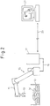
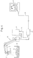
- Figs. 1 to 4 show typical arrangements of robot systems according to first to fourth embodiments of the present invention, respectively.
- the arrangement according to the first embodiment shown in Fig. 1 corresponds to the first and second aspects described above;
- the arrangement according to the second embodiment shown in Fig. 2 corresponds to the third and fourth aspects described above;
- the arrangement according to the third embodiment shown in Fig. 3 corresponds to the fifth and sixth aspects described above;
- the arrangement according to the fourth embodiment shown in Fig. 4 corresponds to the seventh and eighth aspects described above.
- An exemplary application to which the robot system according to each embodiment is applied is an operation in which each of a plurality of workpieces W placed in bulk in a basket-like container 10 is grasped and taken out by a hand 13 mounted at the forward end of a robot arm 11.
- a robot control unit 17 is arranged and connected to the robot 15 and the hand 13 by means of a cable 19.
- the application in which one workpiece W is taken out of the bulk workpieces W is only illustrative and not intended to exclude other applications (welding by real-time tracking using the visual sensor, for example) of the present invention.
- a visual sensor (sensor head) 21 is mounted on the forward end of the robot arm 11. along with the hand 13.
- the visual sensor 21 is typically a three-dimensional visual sensor, such as a stereo type one having two video cameras or a combination of a video camera (photo detector) and a projector for projecting a patterned light such as a slit light or a spot light.
- a visual sensor control unit 23 is provided for controlling an operation (including imaging, projection of patterned light, and detection of reflected light, etc.) of the sensor head 21 and processing signals (including video signals, and reflected light detection signals, etc.) obtained from the sensor head 21 to conduct a three-dimensional measurement.
- the robot control unit 17 and the visual sensor control unit 23 are connected to each other through a data transmitting means 25 in order to exchange data and commands between them.
- a simulation unit 27 is provided for reproducing a situation in which an alarm has occurred, without using the robot (the actual machine) 15.
- the simulation unit 27 receives data required for simulation to reproduce the situation at the time of alarm occurrence and transmits related commands.
- the simulation unit 27 is connected to the robot control unit 17 (in the second and third embodiments) or the visual sensor control unit 23 (in the fourth embodiment) through a communication line 29.
- the robot control unit 17 is a typically-used well-know type in which a main board is equipped with a CPU, a ROM, a RAM, a nonvolatile RAM, and others.
- the system software for controlling the robot 15 is stored in the ROM. This system software is typically copied into the RAM and then executed by the CPU.
- a robot program (operation program) including operation commands prepared by the user is stored in the nonvolatile RAM. The robot program is also typically copied into the RAM and then executed by the CPU.
- the main board of the robot control unit 17 is connected through a servo amplifier to a servo motor for driving the robot arm 11 on one hand and directly connected to an encoder of the servo motor and another signal lines for I/O signals (external input/output signals) on the other hand.
- a teaching panel (not shown) with a display is connected through an input/output interface for the teaching panel to the main board of the robot control unit 17.
- a display may be disposed on the front of the robot control unit 17.
- a typical trouble against which an alarm is issued includes interference (clash) between the robot arm 11 or a robot equipment such as the visual sensor 21 or the hand 13, etc. and other objects.
- a trouble (alarm) considered most liable to occur is interference between the wall of the basket-like container 10 or the workpiece W to be held and another one of the surrounding workpieces.
- a method of detecting an interference is well known and therefore not described in detail below (for example, a method of detecting a clash by use of an external disturbance estimation parameter of a servo system can be used).
- Alarms against troubles other than the interference includes an abnormal operation of the robot 15 such as a large deviation from a taught path, a failure of the hand 13, and a detection failure of the visual sensor 21.
- the visual sensor control unit 23 controls an operation (including imaging, projection of patterned light, and detection of reflected light, etc.) of the sensor head 21, and processes signals (including video signals, and reflected light detection signals, etc.) obtained from the sensor head 21 to conduct a three-dimensional measurement.
- a configuration, the basic functions, etc. of the visual sensor control unit 23 are well known and therefore not described in detail herein.
- the main board is equipped with a CPU, a ROM, a RAM, a nonvolatile RAM, and a frame memory, etc., and a system software for controlling the visual sensor 21 is stored in the ROM.
- This system software is typically copied into the RAM and then executed by the CPU.
- the main board is connected to the visual sensor (sensor head) 21 through a visual sensor I/F, so that information of the image provided by the visual sensor 21, for example, is leaded into a frame memory and processed by the CPU.
- the result of this processing is sent to the robot control unit 17 through the data transmitting means 25, and is used to control the operation of the robot 15.
- the processes executed by the visual sensor 21 and the used images are accumulated in the RAM or the nonvolatile RAM (hard disk, etc.) as a log.
- the visual sensor control unit 23 receives a notification of the alarm occurrence through the data transmitting means 25 and collects sensor history information including information associated with the latest executed visual sensor processing and related information associated with the previously executed visual sensor processing. The collected sensor history information is recorded in the RAM or the nonvolatile RAM.
- This sensor history information includes the following.
- the visual sensor control unit 23 has attached thereto a monitor display (not shown), on which the various accumulated information described above, as well as the image being processed or immediately after being processed, can be displayed. Also, with regard to the process described later, an item can be selected by the operator on the screen using a pointer such as a mouse.
- the simulation unit 27 used in the second to fourth embodiments contains geometric data relating to the robot 15 and the peripheral devices thereof and can simulate the operation of the robot 15. Although a personal computer is a typical example, other conventional simulation units may be used as the simulation unit 27. In the third and fourth embodiments, the simulation unit 27 can execute the same process as the visual sensor control unit 23, and reproduce a specific imaging processing by receiving the image and the parameters necessary for image processing through a communication line from the visual sensor control unit 23.
- the simulation unit 27 has attached thereto a monitor display (not shown), on which the contents of simulation and the various accumulated information described above can be displayed. Also, with regard to the process described later, an item can be selected by the operator on the screen using a pointer such as a mouse.
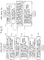
- FIG. 5 represents an outline of an event driven process executed in the visual sensor centrol unit 23 and an interrupt process executed in the robot control unit 17 at the time of alarm occurrence.
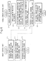
- the flowchart of Fig. 6 represents an outline of a process executed in the robot control unit 17 and the visual sensor control unit 23 to reproduce a situation at the time of alarm occurrence.
- the points of each step executed in the robot control unit 17 are as follows.
- the foregoing processes are an outline of the process executed in preparation for alarm occurrence and an outline of the process executed at the time of alarm occurrence.
- the process for reproducing a situation at the time of alarm occurrence is executed in accordance with the flowchart of Fig. 6 , using the data thus recorded.
- the points of each step executed in the robot control unit 17 are as follows.
- the points of each step executed by the visual sensor control unit 23 are as follows.
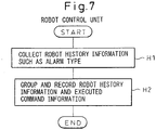
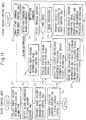
- FIG. 7 represents an outline of an interrupt process executed in the robot control unit 17 at the time of alarm occurrence.
- FIG. 8 represents an outline of a process executed in the robot control unit 17 and the simulation unit 27 to reproduce a situation at the time of alarm occurrence.
- the points of each step executed in the robot control unit 17 are as follows.
- the foregoing processes are an outline of the process executed in preparation for the alarm occurrence and an outline of the process executed at the time of alarm occurrence.
- the process for reproducing a situation at the time of alarm occurrence is executed in accordance with the flowchart of Fig. 8 , using the data thus recorded.
- the points of each step executed in the robot control unit 17 are as follows.
- FIG. 9 represents an outline of an event driven process executed in the visual sensor control unit 23 and an interrupt process executed in the robot control unit 17 at the time of alarm occurrence.
- the flowchart of Fig. 10 represents an outline of a process executed in the robot control unit 17 and the simulation unit 27 to reproduce a situation at the time of alarm occurrence.
- the points of each step executed by the robot control unit 17 are as follows.
- the foregoing processes are an outline of the process executed in preparation for alarm occurrence and an outline of the process executed at the time of alarm occurrence.
- the process for reproducing a situation at the time of alarm occurrence is executed in accordance with the flowchart of Fig. 10 , using the data thus recorded.
- the points of each step executed in the robot control unit 17 are as follows.
- Figs. 11 and 12 processes are executed in accordance with the flowcharts shown in Figs. 11 and 12 .
- the flowchart of Fig. 11 represents an outline of an event driven process executed in the visual sensor control unit 23 and an interrupt process executed at the time of alarm occurrence in the robot control unit 17.
- the flow chart of Fig. 12 represents an outline of a process executed in the visual sensor control unit 23 and the simulation unit 27 to reproduce a situation at the time of alarm occurrence.
- the points of each step executed in the visual sensor control unit 23 are as follows.
- the foregoing processes are an outline of the process executed in preparation for alarm occurrence and an outline of the process executed at the time of alarm occurrence.
- the process for reproducing a situation at the time of alarm occurrence is executed in accordance with the flowchart of Fig. 12 , using the data thus recorded.
- the points of each step executed in the simulation unit 27 are as follows.
- the robot system according to the present invention stores an alarm information together with a position and an orientation at the time of alarm occurrence, the target position and orientation at the time of alarm occurrence, the result of the image processing and the related data which has affected the robot operation, and reproduces the alarm situation based on this information.
- the reproduction can be implemented by either the on-line reproduction by means of the actual robot machine or the off-line reproduction by means of the simulation unit (arranged at a remote place, for example).
- this reproduction makes it possible not only to confirm the specifics of the trouble, but also to know the detail of the situation of the robot (the orientation thereof at the time of alarm occurrence and the orientation thereof in the process before alarm occurrence) at the time of trouble occurrence, thereby facilitating the tracing of the cause and the removal of the problem.
- the simulation unit is used for reproducing the trouble situation by simulation, the change of the robot program or the values of the parameters for image processing can be carried out on line to remove the problem. Therefore, the preventive measure can be taken very efficiently.
Landscapes
- Engineering & Computer Science (AREA)
- Robotics (AREA)
- Mechanical Engineering (AREA)
- Human Computer Interaction (AREA)
- Manufacturing & Machinery (AREA)
- Physics & Mathematics (AREA)
- General Physics & Mathematics (AREA)
- Automation & Control Theory (AREA)
- Manipulator (AREA)
- Numerical Control (AREA)
Claims (11)
- Robotersystem, das dazu eingerichtet ist, zum Zeitpunkt eines Auftretens eines Alarms eine Situation wiederherzustellen, wobei das Robotersystem umfasst:einen Roboter; undeinen über ein Datenübertragungsmittel mit dem Roboter verbundenen visuellen Sensor zum Messen einer Position und/oder einer Orientierung eines Objekts nach Maßgabe eines Befehls von dem Roboter und zum Übertragen eines Messergebnisses an den Roboter,wobei der Roboter umfasst:ein Mittel zum Senden, auf ein Auftreten eines vorgegebenen Alarms in dem Roboter im Betrieb hin, einer Benachrichtigung über das Auftreten des Alarms und eines Betriebszustands des Roboters zum Zeitpunkt des Auftretens des Alarms als Roboterverlaufsinformation an den visuellen Sensor;ein Mittel zum Empfangen der Roboterverlaufsinformation von dem visuellen Sensor; undein Mittel zum Wiederherstellen des Betriebszustands des Roboters zum Zeitpunkt des Auftretens des Alarms unter Verwendung der empfangenen Roboterverlaufsinformation; undwobei der visuelle Sensor umfasst:ein Akkumulationsmittel zum Sammeln von durch Messen erhaltener Verarbeitungsmessinformation;ein Aufzeichnungsmittel zum Aufzeichnen der Roboterverlaufsinformation auf das Empfangen der Benachrichtigung über das Auftreten des Alarms und der Roboterverlaufsinformation von dem Roboter hin und gleichzeitigem Auswählen der Verarbeitungsmessinformation in Bezug auf den Roboterbetrieb zum Zeitpunkt des Auftretens des Alarms aus der in dem Akkumulationsmittel gesammelten Verarbeitungsmessinformation und Aufzeichnen der ausgewählten Verarbeitungsmessinformation als Sensorverlaufsinformation;ein Mittel zum Senden der in dem Aufzeichnungsmittel aufgezeichneten Roboterverlaufsinformation an den Roboter; undein Mittel zum Wiederherstellen eines Verarbeitungsprozesses des visuellen Sensors unter Verwendung der Sensorverlaufsinformation.
- Robotersystem nach Anspruch 1,
wobei der Roboter ferner ein Mittel zum temporären Speichern einer vorbestimmten Menge der zuletzt ausgeführten Betriebsbefehle als Information der ausgeführten Befehle umfasst;
wobei das Mittel zum Senden des Roboters, auf das Auftreten des vorgegebenen Alarms in dem Roboter im Betrieb hin, die Benachrichtigung über das Auftreten des Alarms, die Information der ausgeführten Befehle und den Betriebszustand des Roboters zum Zeitpunkt des Auftretens des Alarms als die Roboterverlaufsinformation an den visuellen Sensor sendet;
wobei das Mittel zum Empfangen des Roboters die Information der ausgeführten Befehle und die Roboterverlaufsinformation von dem visuellen Sensor empfängt;
wobei das Mittel zum Wiederherstellen des Roboters den Betriebszustand des Roboters vor dem sowie zum Zeitpunkt des Auftretens des Alarms unter Verwendung der empfangenen Information der ausgeführten Befehle und der empfangenen Roboterverlaufsinformation wiederherstellt;
wobei das Aufzeichnungsmittel des visuellen Sensors, auf das Empfangen der Benachrichtigung des Auftretens des Alarms hin, die Information der ausgeführten Befehle und die Roboterverlaufsinformation von dem Roboter, die Information der ausgeführten Befehle und die Roboterverlaufsinformation aufzeichnet, die Verarbeitungsmessinformation in Bezug auf den Roboterbetrieb zum Zeitpunkt des Auftretens des Alarms aus der in dem Akkumulationsmittel gesammelten Verarbeitungsmessinformation auswählt, und die ausgewählte Verarbeitungsmessinformationen als die Sensorverlaufsinformation aufzeichnet; und
wobei das Mittel zum Senden des visuellen Sensors die Information der ausgeführten Befehle und die Roboterverlaufsinformation, die in dem Aufzeichnungsmittel aufgezeichnet ist, an den Roboter sendet. - Robotersystem nach Anspruch 1 oder 2, wobei die Sensorverlaufsinformation eine Information umfasst, die ein mit dem visuellen Sensor aufgenommenes Bild, einen mittels des visuellen Sensors verarbeiteten Inhalt und/oder ein Ergebnis der Messverarbeitung in dem visuellen Sensor darstellt.
- Robotersystem, das dazu eingerichtet ist, zum Zeitpunkt eines Auftretens eines Alarms eine Situation wiederherzustellen, wobei das Robotersystem umfasst:einen Roboter; undeine mit dem Roboter über eine Kommunikationsleitung verbundene Simulationseinheit zum Simulieren von Tätigkeiten des Roboters,wobei der Roboter umfasst:ein Mittel zum Aufzeichnen, auf das Auftreten eines vorgegebenen Alarms in dem Roboter im Betrieb hin, eines Betriebszustands des Roboters zum Zeitpunkt des Auftretens des Alarms als Roboterverlaufsinformation; undein Mittel zum Übertragen der Roboterverlaufsinformation über die Kommunikationsleitung an die Simulationseinheit, undwobei die Simulationseinheit umfasst:dadurch gekennzeichnet, dass das Robotersystem ferner einen über ein Datenübertragungsmittel mit dem Roboter verbundenen visuellen Sensor zum Messen einer Position und/oder einer Orientierung eines Objekts nach Maßgabe eines Befehls von dem Roboter und zum Übertragen eines Messergebnisses an den Roboter umfasst;ein Mittel zum Empfangen der von dem Roboter übertragenen Roboterverlaufsinformation; undein Mittel zum Wiederherstellen des Betriebszustands des Roboters zum Zeitpunkt des Auftretens des Alarms durch Simulation unter Verwendung der empfangenen Roboterverlaufsinformation,wobei die Simulationseinheit die Tätigkeiten des Roboters und/oder die Verarbeitungen des visuellen Sensors simuliert,wobei das Mittel zum Aufzeichnen des Roboters, auf das Auftreten des vorgegebenen Alarms in dem Roboter im Betrieb hin, ein Auftreten eines Alarms an den visuellen Sensor meldet und den Betriebszustand des Roboters zum Zeitpunkt des Auftretens des Alarms als Roboterverlaufsinformation aufzeichnet;wobei der Roboter ferner ein Mittel zum Empfangen von Verarbeitungsmessinformation des visuellen Sensors in Bezug auf den Roboterbetrieb zum Zeitpunkt des Auftretens des Alarms von dem visuellen Sensor und Aufzeichnen der Verarbeitungsmessinformation als Sensorverlaufsinformation;wobei das Mittel zum Übertragen des Roboters die Roboterverlaufsinformation und die Sensorverlaufsinformation durch die Kommunikationsleitung an die Simulationseinheit überträgt,wobei der visuelle Sensor umfasst:ein Akkumulationsmittel zum Sammeln von durch Messen erhaltener Verarbeitungsmessinformation; undein Mittel zum Auswählen, auf das Empfangen der Benachrichtigung des Auftretens des Alarms von dem Roboter hin, der Verarbeitungsmessinformation in Bezug auf den Roboterbetrieb zum Zeitpunkt des Auftretens des Alarms aus der in dem Akkumulationsmittel gesammelten Verarbeitungsmessinformation und Übertragen der ausgewählten Verarbeitungsmessinformation an den Roboter,wobei das Mittel zum Empfangen der Simulationseinheit die von dem Roboter übertragene Roboterverlaufsinformation und Sensorverlaufsinformation empfängt; undwobei die Simulationseinheit ferner ein Mittel zum Wiederherstellen des Verarbeitungsprozesses des visuellen Sensors durch Simulation unter Verwendung der empfangenen Sensorverlaufsinformation umfasst.
- Robotersystem nach Anspruch 4,
wobei der Roboter ferner ein Mittel zum temporären Speichern einer vorbestimmten Menge der zuletzt ausgeführten Betriebsbefehle als Information der ausgeführten Befehle umfasst;
wobei das Mittel zum Übertragen des Roboters die Information der ausgeführten Befehle, die Roboterverlaufsinformation und die Sensorverlaufsinformation über die Kommunikationsleitung an die Simulationseinheit überträgt,
wobei das Mittel zum Empfangen der Simulationseinheit die von dem Roboter übertragene Information der ausgeführten Befehle, Roboterverlaufsinformation und Sensorverlaufsinformation empfängt; und
wobei das Mittel zum Wiederherstellen des Betriebszustands des Roboters den Betriebszustand des Roboters vor dem und zum Zeitpunkt des Auftretens des Alarms durch Simulation unter Verwendung der empfangenen Information der ausgeführten Befehle und der empfangenen Roboterverlaufsinformation wiederherstellt. - Robotersystem, das dazu eingerichtet ist, zum Zeitpunkt eines Auftretens eines Alarms eine Situation wiederherzustellen, wobei das Robotersystem umfasst:einen Roboter;einen über ein Datenübertragungsmittel mit dem Roboter verbundenen visuellen Sensor zum Messen einer Position und/oder einer Orientierung eines Objekts nach Maßgabe eines Befehls von dem Roboter und zum Übertragen eines Messergebnisses an den Roboter; undeine mit dem Roboter über eine Kommunikationsleitung verbundene Simulationseinheit zum Simulieren der Tätigkeiten des Roboters und/oder der Verarbeitungen des visuellen Sensors,wobei der Roboter umfasst:ein Mittel zum Senden, auf ein Auftreten eines vorgegebenen Alarms in dem Roboter im Betrieb hin, einer Benachrichtigung über das Auftreten des Alarms und eines Betriebszustands des Roboters zum Zeitpunkt des Auftretens des Alarms als Roboterverlaufsinformation an den visuellen Sensor,wobei der visuelle Sensor umfasst:ein Akkumulationsmittel zum Sammeln von durch Messen erhaltener Verarbeitungsmessinformation;ein Aufzeichnungsmittel zum Aufzeichnen der Roboterverlaufsinformation auf das Empfangen der Benachrichtigung über das Auftreten des Alarms und der Roboterverlaufsinformation von dem Roboter hin, und gleichzeitigem Auswählen der Verarbeitungsmessinformation in Bezug auf den Roboterbetrieb zum Zeitpunkt des Auftretens des Alarms aus der in dem Akkumulationsmittel gesammelten Verarbeitungsmessinformation und Aufzeichnen der ausgewählten Verarbeitungsmessinformation als Sensorverlaufsinformation; undein Mittel zum Übertragen der Roboterverlaufsinformation und der Sensorverlaufsinformation über die Kommunikationsleitung an die Simulationseinheit,wobei die Simulationseinheit umfasst:ein Mittel zum Empfangen der von dem visuellen Sensor übertragenen Roboterverlaufsinformation und Sensorverlaufsinformation;ein Mittel zum Wiederherstellen des Betriebszustands des Roboters zum Zeitpunkt des Auftretens des Alarms durch Simulation unter Verwendung der empfangenen Roboterverlaufsinformation; undein Mittel zum Wiederherstellen des Betriebszustands des Roboters zum Zeitpunkt des Auftretens des Alarms durch Simulation unter Verwendung der empfangenen Sensorverlaufsinformation.
- Robotersystem nach Anspruch 6,
wobei die Simulationseinheit über die Kommunikationsleitung mit dem visuellen Sensor anstelle des Roboters verbunden ist,
wobei der Roboter ferner Mittel zum temporären Speichern einer vorbestimmten Menge der zuletzt ausgeführten Betriebsbefehle als Information der ausgeführten Befehle umfasst;
wobei das Mittel zum Senden des Roboters, auf das Auftreten des vorgegebenen Alarms in dem Roboter im Betrieb hin, die Benachrichtigung über das Auftreten des Alarms, die Information der ausgeführten Befehle und den Betriebszustand des Roboters zum Zeitpunkt des Auftretens des Alarms als die Roboterverlaufsinformation an den visuellen Sensor sendet,
wobei das Mittel zum Aufzeichnen des visuellen Sensors, auf das Empfangen der Benachrichtigung des Auftretens des Alarms hin, die Information der ausgeführten Befehle und die Roboterverlaufsinformation von dem Roboter, die Information der ausgeführten Befehle und die Roboterverlaufsinformation aufzeichnet, die Verarbeitungsmessinformation in Bezug auf den Roboterbetrieb zum Zeitpunkt des Auftretens des Alarms aus der in dem Akkumulationsmittel gesammelten Verarbeitungsmessinformation auswählt, und die ausgewählte Verarbeitungsmessinformationen als die Sensorverlaufsinformation aufzeichnet;
wobei das Mittel zum Übertragen des visuellen Sensors die Information der ausgeführten Befehle, die Roboterverlaufsinformation und die Sensorverlaufsinformation über die Kommunikationsleitung an die Simulationseinheit überträgt,
wobei das Mittel zum Empfangen der Simulationseinheit die von dem visuellen Sensor übertragene Information der ausgeführten Befehle, Roboterverlaufsinformation und Sensorverlaufsinformation empfängt; und
wobei das Mittel zum Wiederherstellen des Betriebszustands des Roboters den Betriebszustand des Roboters vor dem und zum Zeitpunkt des Auftretens des Alarms durch Simulation unter Verwendung der empfangenen Information der ausgeführten Befehle und der empfangenen Roboterverlaufsinformation wiederherstellt. - Robotersystem nach Anspruch 4, 5, 6 oder 7, wobei die Roboterverlaufsinformation eine Information umfasst, die eine Position, die der Roboter erreicht hat, eine Zielposition, auf die der Roboter abzielt, einen von dem Roboter zum Agieren verwendeten Interpolationsmodus, einen in dem Roboter erzeugten Alarm und/oder einen Zeitpunkt des Auftretens des Alarms darstellt, und
wobei die Sensorverlaufsinformation eine Information umfasst, die ein mit dem visuellen Sensor aufgenommenes Bild, einen mittels des visuellen Sensors verarbeiteten Inhalt und/oder ein Ergebnis der Messverarbeitung in dem visuellen Sensor darstellt. - Robotersystem nach Anspruch 4, 5, 6 oder 7, wobei die Kommunikationsleitung dazu eingerichtet ist, zwischen einem verbundenen Zustand und einem getrennten Zustand schaltbar zu sein.
- Robotersystem nach Anspruch 4, 5, 6 oder 7, wobei die Simulationseinheit dazu eingerichtet ist, ein Roboterprogramm zu laden, das den Betrieb des Roboters über die Kommunikationsleitung beschreibt, und eine Funktion zum Ändern eines Lehrinhalts des Roboterprogramms auf der Simulationseinheit und anschließenden Anwenden des geändertes Roboterprogramm in dem Roboter hat.
- Robotersystem nach Anspruch 4, 5, 6 oder 7, wobei die Simulationseinheit dazu eingerichtet ist, Verarbeitungsparameter des visuellen Sensors zu laden, die einen Prozess des visuellen Sensors über die Kommunikationsleitung definieren, und eine Funktion zum Ändern des Inhalts der Verarbeitungsparameter des visuellen Sensors in der Simulationseinheit und anschließenden Anwenden der geänderten Verarbeitungsparameter des visuellen Sensors in dem visuellen Sensor hat.
Applications Claiming Priority (2)
| Application Number | Priority Date | Filing Date | Title |
|---|---|---|---|
| JP2003337892A JP3834307B2 (ja) | 2003-09-29 | 2003-09-29 | ロボットシステム |
| JP2003337892 | 2003-09-29 |
Publications (3)
| Publication Number | Publication Date |
|---|---|
| EP1518648A2 EP1518648A2 (de) | 2005-03-30 |
| EP1518648A3 EP1518648A3 (de) | 2010-11-03 |
| EP1518648B1 true EP1518648B1 (de) | 2017-08-30 |
Family
ID=34191577
Family Applications (1)
| Application Number | Title | Priority Date | Filing Date |
|---|---|---|---|
| EP04023038.5A Expired - Lifetime EP1518648B1 (de) | 2003-09-29 | 2004-09-28 | Robotisches System mit Mitteln zur Wiedergabe eines Alarmzustandes |
Country Status (3)
| Country | Link |
|---|---|
| US (1) | US7590468B2 (de) |
| EP (1) | EP1518648B1 (de) |
| JP (1) | JP3834307B2 (de) |
Cited By (1)
| Publication number | Priority date | Publication date | Assignee | Title |
|---|---|---|---|---|
| DE102016009030B4 (de) | 2015-07-31 | 2019-05-09 | Fanuc Corporation | Vorrichtung für maschinelles Lernen, Robotersystem und maschinelles Lernsystem zum Lernen eines Werkstückaufnahmevorgangs |
Families Citing this family (78)
| Publication number | Priority date | Publication date | Assignee | Title |
|---|---|---|---|---|
| US6594552B1 (en) * | 1999-04-07 | 2003-07-15 | Intuitive Surgical, Inc. | Grip strength with tactile feedback for robotic surgery |
| JP3905073B2 (ja) * | 2003-10-31 | 2007-04-18 | ファナック株式会社 | アーク溶接ロボット |
| JP4056542B2 (ja) * | 2005-09-28 | 2008-03-05 | ファナック株式会社 | ロボットのオフライン教示装置 |
| DE102006000635A1 (de) * | 2006-01-03 | 2007-08-09 | Kuka Roboter Gmbh | Vorrichtung zum Steuern mindestens einer Maschine |
| JP4153528B2 (ja) * | 2006-03-10 | 2008-09-24 | ファナック株式会社 | ロボットシミュレーションのための装置、プログラム、記録媒体及び方法 |
| US7853356B2 (en) * | 2006-04-14 | 2010-12-14 | Fanuc Robotics America, Inc. | Method for optimizing a robot program and a robot system |
| JP4238256B2 (ja) * | 2006-06-06 | 2009-03-18 | ファナック株式会社 | ロボットシミュレーション装置 |
| US7654348B2 (en) * | 2006-10-06 | 2010-02-02 | Irobot Corporation | Maneuvering robotic vehicles having a positionable sensor head |
| US7974737B2 (en) * | 2006-10-31 | 2011-07-05 | GM Global Technology Operations LLC | Apparatus and method of automated manufacturing |
| ATE542644T1 (de) * | 2006-12-22 | 2012-02-15 | Abb Research Ltd | Steuersystem |
| JP4261588B2 (ja) | 2007-01-18 | 2009-04-30 | ファナック株式会社 | 制御装置 |
| JP2008296330A (ja) * | 2007-05-31 | 2008-12-11 | Fanuc Ltd | ロボットシミュレーション装置 |
| DE102007060653A1 (de) * | 2007-12-15 | 2009-06-18 | Abb Ag | Positionsermittlung eines Objektes |
| ATE452005T1 (de) | 2008-02-13 | 2010-01-15 | Abb As | System und verfahren zur visualisierung von verfahrensfehlern |
| US9842192B2 (en) * | 2008-07-11 | 2017-12-12 | Intouch Technologies, Inc. | Tele-presence robot system with multi-cast features |
| JP2011108044A (ja) * | 2009-11-18 | 2011-06-02 | Fanuc Ltd | N個のロボットを同時に制御するロボット制御装置 |
| JP5665333B2 (ja) * | 2010-03-10 | 2015-02-04 | キヤノン株式会社 | 情報処理装置および情報処理装置の制御方法 |
| JP5544957B2 (ja) * | 2010-03-18 | 2014-07-09 | 株式会社Ihi | カメラ脱着ロボット装置、ワーク把持システム、およびワーク把持方法 |
| JP5767464B2 (ja) * | 2010-12-15 | 2015-08-19 | キヤノン株式会社 | 情報処理装置、情報処理装置の制御方法、およびプログラム |
| US9522595B2 (en) | 2011-01-27 | 2016-12-20 | Irobot Defense Holdings, Inc. | Small unmanned ground vehicle |
| US9346499B2 (en) | 2011-01-27 | 2016-05-24 | Irobot Corporation | Resilient wheel assemblies |
| US8965563B2 (en) * | 2011-04-04 | 2015-02-24 | Palo Alto Research Incorporated | High throughput parcel handling |
| JP6015178B2 (ja) * | 2012-07-11 | 2016-10-26 | オムロン株式会社 | 安全システム |
| JP5642738B2 (ja) * | 2012-07-26 | 2014-12-17 | ファナック株式会社 | バラ積みされた物品をロボットで取出す装置及び方法 |
| JP5469216B2 (ja) * | 2012-07-31 | 2014-04-16 | ファナック株式会社 | バラ積みされた物品をロボットで取出す装置 |
| CN102794767B (zh) * | 2012-08-31 | 2014-09-24 | 江南大学 | 视觉引导的机器人关节空间b样条轨迹规划方法 |
| WO2014128893A1 (ja) * | 2013-02-21 | 2014-08-28 | 三菱電機株式会社 | 設備機器、設備機器解析システム、設備機器シミュレーション装置、運転制御方法、運転シミュレーション方法、及びプログラム |
| JP5754454B2 (ja) * | 2013-03-18 | 2015-07-29 | 株式会社安川電機 | ロボットピッキングシステム及び被加工物の製造方法 |
| JP5929854B2 (ja) * | 2013-07-31 | 2016-06-08 | 株式会社安川電機 | ロボットシステムおよび被加工物の製造方法 |
| JP5877857B2 (ja) | 2014-03-10 | 2016-03-08 | ファナック株式会社 | ワークの取出工程をシミュレーションするロボットシミュレーション装置 |
| JP5778311B1 (ja) * | 2014-05-08 | 2015-09-16 | 東芝機械株式会社 | ピッキング装置およびピッキング方法 |
| CN104062902B (zh) * | 2014-05-15 | 2017-01-04 | 江南大学 | Delta机器人时间最优轨迹规划方法 |
| PT2982625T (pt) * | 2014-08-08 | 2019-02-22 | Sanovo Tech Italia S R L | Despaletizador para bandejas de ovos |
| CN104400788A (zh) * | 2014-12-03 | 2015-03-11 | 安徽省库仑动力自动化科技有限公司 | 一种用于废旧铅电池拆解的视觉识别机器人系统 |
| US10723024B2 (en) | 2015-01-26 | 2020-07-28 | Duke University | Specialized robot motion planning hardware and methods of making and using same |
| CN104858877B (zh) * | 2015-04-28 | 2016-08-31 | 国家电网公司 | 高压线路跌落开关自动更换控制系统的控制方法 |
| CN104942816B (zh) * | 2015-04-28 | 2017-01-18 | 国家电网公司 | 基于激光技术的线路跌落开关自动更换控制系统及方法 |
| JP6862081B2 (ja) * | 2015-06-23 | 2021-04-21 | キヤノン株式会社 | ロボットシステムの制御方法、制御プログラム、コンピュータ読み取り可能な記録媒体、およびロボットシステム |
| JP6240689B2 (ja) | 2015-07-31 | 2017-11-29 | ファナック株式会社 | 人の行動パターンを学習する機械学習装置、ロボット制御装置、ロボットシステム、および機械学習方法 |
| JP6522488B2 (ja) * | 2015-07-31 | 2019-05-29 | ファナック株式会社 | ワークの取り出し動作を学習する機械学習装置、ロボットシステムおよび機械学習方法 |
| CN108025432B (zh) * | 2015-09-17 | 2021-05-07 | Abb瑞士股份有限公司 | 部件馈送器以及包括部件馈送器的用于拾取部件的系统 |
| SE539323C2 (en) | 2015-10-19 | 2017-07-04 | Husqvarna Ab | Improved control of remote demolition robot |
| CN105563501A (zh) * | 2015-12-07 | 2016-05-11 | 沈阳恒天机器人制造有限公司 | 3d视觉机器人 |
| EP3437810B1 (de) | 2016-03-30 | 2022-07-13 | Panasonic Intellectual Property Management Co., Ltd. | Datenspeichervorrichtung, robotersystem und datenspeicherverfahren |
| US9943963B2 (en) * | 2016-04-12 | 2018-04-17 | Fetch Robotics, Inc. | System and method for determining and promoting safety of a robotic payload |
| EP3537248A1 (de) | 2016-06-10 | 2019-09-11 | Duke University | Bewegungsplanung für autonome fahrzeuge und rekonfigurierbare bewegungsplanungsprozessoren |
| US11477264B2 (en) * | 2016-06-29 | 2022-10-18 | Nicira, Inc. | Network workflow replay tool |
| CN106364903A (zh) * | 2016-08-18 | 2017-02-01 | 上海交通大学 | 单目立体视觉堆叠工件分拣方法 |
| JP6517762B2 (ja) * | 2016-08-23 | 2019-05-22 | ファナック株式会社 | 人とロボットが協働して作業を行うロボットの動作を学習するロボットシステム |
| JP6514171B2 (ja) | 2016-09-27 | 2019-05-15 | ファナック株式会社 | 最適な物品把持経路を学習する機械学習装置、及び機械学習方法 |
| JP6450727B2 (ja) * | 2016-10-28 | 2019-01-09 | ファナック株式会社 | ロボットが行う物品整列作業のシミュレーションのための装置、方法、プログラム及び記録媒体 |
| JP6392908B2 (ja) * | 2017-01-12 | 2018-09-19 | ファナック株式会社 | 視覚センサの異常原因推定システム |
| JP6490132B2 (ja) * | 2017-03-31 | 2019-03-27 | ファナック株式会社 | ロボットの制御装置、機械学習装置及び機械学習方法 |
| WO2019139815A1 (en) | 2018-01-12 | 2019-07-18 | Duke University | Apparatus, method and article to facilitate motion planning of an autonomous vehicle in an environment having dynamic objects |
| TWI822729B (zh) | 2018-02-06 | 2023-11-21 | 美商即時機器人股份有限公司 | 用於儲存一離散環境於一或多個處理器之一機器人之運動規劃及其改良操作之方法及設備 |
| EP3542970A1 (de) * | 2018-03-20 | 2019-09-25 | Siemens Aktiengesellschaft | Verfahren, vorrichtung und system zur wiedergabe der bewegung eines roboters |
| ES2928250T3 (es) | 2018-03-21 | 2022-11-16 | Realtime Robotics Inc | Planificación del movimiento de un robot para diversos entornos y tareas y mejora del funcionamiento del mismo |
| EP3795310A4 (de) | 2018-05-16 | 2021-07-14 | Panasonic Intellectual Property Management Co., Ltd. | Robotervorrichtung |
| AT521390B1 (de) * | 2018-06-29 | 2021-11-15 | Wittmann Tech Gmbh | Verfahren zur laufenden Speicherung von internen Betriebszuständen und zur Visualisierung von zeitlich zurückliegenden Ablaufsequenzen sowie Roboter und/oder Robotsteuerung hierfür |
| US12330310B2 (en) | 2018-08-23 | 2025-06-17 | Realtime Robotics, Inc. | Collision detection useful in motion planning for robotics |
| US12204336B2 (en) | 2018-12-04 | 2025-01-21 | Duke University | Apparatus, method and article to facilitate motion planning in an environment having dynamic objects |
| WO2020214723A1 (en) | 2019-04-17 | 2020-10-22 | Real Time Robotics, Inc. | Motion planning graph generation user interface, systems, methods and articles |
| JP7479064B2 (ja) | 2019-06-03 | 2024-05-08 | リアルタイム ロボティクス, インコーポレーテッド | 動的障害物を有する環境における動作計画を容易にする装置、方法及び物品 |
| JP7396819B2 (ja) * | 2019-06-21 | 2023-12-12 | ファナック株式会社 | ロボット装置の動作を動画にて撮像するカメラを備える監視装置 |
| TWI873149B (zh) | 2019-06-24 | 2025-02-21 | 美商即時機器人股份有限公司 | 用於多個機械手臂於共用工作空間中之移動規劃系統及方法 |
| EP3993963B1 (de) | 2019-08-23 | 2025-07-16 | Realtime Robotics, Inc. | Bewegungsplanung für roboter zur optimierung der geschwindigkeit bei bewahrung der grenzwerte bei beschleunigung und ruckeln |
| TWI887329B (zh) | 2020-01-22 | 2025-06-21 | 美商即時機器人股份有限公司 | 於多機器人操作環境中之機器人之建置之方法及系統 |
| CN111168686B (zh) * | 2020-02-25 | 2021-10-29 | 深圳市商汤科技有限公司 | 物体的抓取方法、装置、设备及存储介质 |
| US12194639B2 (en) | 2020-03-18 | 2025-01-14 | Realtime Robotics, Inc. | Digital representations of robot operational environment, useful in motion planning for robots |
| GB2593734B (en) * | 2020-03-31 | 2025-09-03 | Cmr Surgical Ltd | Testing unit for testing a surgical robotic system |
| JP6898506B1 (ja) | 2020-07-01 | 2021-07-07 | 株式会社安川電機 | 制御システム、ロボットシステム及び制御方法 |
| WO2022215178A1 (ja) * | 2021-04-06 | 2022-10-13 | ファナック株式会社 | 選択装置、通信制御装置、シミュレーション装置、及び記録媒体 |
| CN117320854A (zh) * | 2021-05-25 | 2023-12-29 | 发那科株式会社 | 机器人模拟装置 |
| US20240177461A1 (en) * | 2021-06-23 | 2024-05-30 | Fanuc Corporation | Teaching device |
| JP2023028945A (ja) * | 2021-08-20 | 2023-03-03 | パナソニックIpマネジメント株式会社 | ロボット制御システム及びイベント履歴情報管理方法、プログラム |
| WO2023047588A1 (ja) * | 2021-09-27 | 2023-03-30 | ファナック株式会社 | ロボットシステム |
| US20240383134A1 (en) * | 2021-09-30 | 2024-11-21 | Fanuc Corporation | Teaching device and robot system |
| US20250053150A1 (en) | 2021-12-27 | 2025-02-13 | Fanuc Corporation | Simulation device for robot or machine tool |
Family Cites Families (24)
| Publication number | Priority date | Publication date | Assignee | Title |
|---|---|---|---|---|
| US4517652A (en) * | 1982-03-05 | 1985-05-14 | Texas Instruments Incorporated | Hand-held manipulator application module |
| JPH0789287B2 (ja) * | 1985-11-07 | 1995-09-27 | 三菱電機株式会社 | ロボットのプログラミング方法 |
| JP2662990B2 (ja) | 1988-07-28 | 1997-10-15 | ファナック株式会社 | ロボット動作特性の改良機能を備えたロボット制御装置 |
| JPH052205A (ja) | 1991-06-26 | 1993-01-08 | Canon Inc | フオーカス指令装置 |
| US5495410A (en) * | 1994-08-12 | 1996-02-27 | Minnesota Mining And Manufacturing Company | Lead-through robot programming system |
| US5798627A (en) * | 1995-01-04 | 1998-08-25 | Gilliland; Malcolm T. | Method for simultaneous operation of robot welders |
| US6243625B1 (en) * | 1996-04-12 | 2001-06-05 | N E D Corp. | Automated quarry operation with communication interface |
| DE19617620A1 (de) | 1996-05-02 | 1997-11-13 | Traub Drehmaschinen Gmbh | Diagnoseeinrichtung |
| JPH09311715A (ja) | 1996-05-22 | 1997-12-02 | Fanuc Ltd | ロボットの異常発生履歴表示方法 |
| JPH10309683A (ja) | 1997-05-07 | 1998-11-24 | Sankyo Seiki Mfg Co Ltd | ロボットのエラー解析方法及びロボット |
| CA2228574A1 (en) * | 1997-06-05 | 1999-08-02 | Attention Control Systems, Inc. | An automatic planning and cueing system and method |
| JPH11134017A (ja) * | 1997-10-27 | 1999-05-21 | Honda Motor Co Ltd | オフラインティーチング方法 |
| JPH11167404A (ja) | 1997-12-04 | 1999-06-22 | Yaskawa Electric Corp | 数値制御装置 |
| JP3132463B2 (ja) * | 1998-04-07 | 2001-02-05 | 松下電器産業株式会社 | ロボット制御装置 |
| DE19857436A1 (de) * | 1998-12-12 | 2000-06-21 | Kuka Roboter Gmbh | Verfahren zum Behandeln des Spannungsabfalls in der Steuerung eines Roboters und zum Wiederanfahren eines Roboters nach Spannungsabfall |
| JP2000263481A (ja) | 1999-03-12 | 2000-09-26 | Meidensha Corp | ビンピッキング装置 |
| JP3673117B2 (ja) * | 1999-06-14 | 2005-07-20 | 和泉電気株式会社 | 組立装置とそのためのトレイシステム |
| JP4122652B2 (ja) * | 1999-09-27 | 2008-07-23 | 松下電器産業株式会社 | ロボットの制御装置 |
| JP3645460B2 (ja) | 1999-12-28 | 2005-05-11 | 株式会社東芝 | 事故対応ロボットシステム |
| JP2001277163A (ja) | 2000-04-03 | 2001-10-09 | Sony Corp | ロボットの制御装置及び制御方法 |
| KR100345150B1 (ko) * | 2000-09-29 | 2002-07-24 | 현대자동차주식회사 | 레이저 측정기를 이용한 로봇 위치 보정 방법 |
| JP3673725B2 (ja) * | 2001-04-05 | 2005-07-20 | ファナック株式会社 | ロボット用情報処理システム |
| JP3782679B2 (ja) * | 2001-05-09 | 2006-06-07 | ファナック株式会社 | 干渉回避装置 |
| US6836700B2 (en) * | 2002-07-29 | 2004-12-28 | Advanced Robotic Technologies, Inc. | System and method generating a trajectory for an end effector |
-
2003
- 2003-09-29 JP JP2003337892A patent/JP3834307B2/ja not_active Expired - Fee Related
-
2004
- 2004-09-28 EP EP04023038.5A patent/EP1518648B1/de not_active Expired - Lifetime
- 2004-09-29 US US10/952,101 patent/US7590468B2/en not_active Expired - Fee Related
Non-Patent Citations (1)
| Title |
|---|
| None * |
Cited By (1)
| Publication number | Priority date | Publication date | Assignee | Title |
|---|---|---|---|---|
| DE102016009030B4 (de) | 2015-07-31 | 2019-05-09 | Fanuc Corporation | Vorrichtung für maschinelles Lernen, Robotersystem und maschinelles Lernsystem zum Lernen eines Werkstückaufnahmevorgangs |
Also Published As
| Publication number | Publication date |
|---|---|
| EP1518648A3 (de) | 2010-11-03 |
| JP2005103681A (ja) | 2005-04-21 |
| EP1518648A2 (de) | 2005-03-30 |
| JP3834307B2 (ja) | 2006-10-18 |
| US7590468B2 (en) | 2009-09-15 |
| US20050071048A1 (en) | 2005-03-31 |
Similar Documents
| Publication | Publication Date | Title |
|---|---|---|
| EP1518648B1 (de) | Robotisches System mit Mitteln zur Wiedergabe eines Alarmzustandes | |
| KR102860794B1 (ko) | 상태 감시 장치, 상태 이상 판별 방법 및 상태 이상 판별 프로그램 | |
| CN110231802B (zh) | 机器人控制装置、记录的生成方法以及存储介质 | |
| US5715388A (en) | Computer system for controlling an industrial robot subsystem which can monitor and detect abnormalities therein | |
| JP7079420B2 (ja) | 異常診断装置及び異常診断方法 | |
| CN117282580A (zh) | 一种用于喷涂流水线的智能机械手及控制方法 | |
| JP6927421B2 (ja) | 異常判定装置、異常判定システム及び異常判定方法 | |
| CN113031521A (zh) | 数控机床的刀具监控系统和方法 | |
| JP7396819B2 (ja) | ロボット装置の動作を動画にて撮像するカメラを備える監視装置 | |
| JP5236392B2 (ja) | 理論機械位置算出手段を有する数値制御装置 | |
| EP1028307B1 (de) | Verfahren und vorrichtung für die instandhaltung eines messinstrumentes für koordinaten- und oberflächenmessungen | |
| JP3913666B2 (ja) | シミュレーション装置 | |
| JP2005216213A (ja) | 故障診断システム及び故障診断方法 | |
| JP3360969B2 (ja) | プラント点検支援装置 | |
| JP7674388B2 (ja) | 支援装置及び機械システム | |
| JPS5947322B2 (ja) | ストロ−クオ−バ−検知方法 | |
| JP6816176B2 (ja) | 測定システム | |
| CN120080320A (zh) | 一种转子支架纵焊缝机器人自动化打磨控制系统及方法 | |
| JP7056733B2 (ja) | 異常検出装置及び異常検出方法 | |
| JPH07200019A (ja) | ロボット制御装置 | |
| JP3040906B2 (ja) | ロボットの動作時間評価方法および装置 | |
| Solvang et al. | SAPIR: Supervised and adaptive programming of industrial robots | |
| US20250301206A1 (en) | Video generation device and computer-readable storage medium | |
| CN213634179U (zh) | 自动化装置 | |
| Rzeznik | In‐line laser measurement in the assembly process |
Legal Events
| Date | Code | Title | Description |
|---|---|---|---|
| PUAI | Public reference made under article 153(3) epc to a published international application that has entered the european phase |
Free format text: ORIGINAL CODE: 0009012 |
|
| AK | Designated contracting states |
Kind code of ref document: A2 Designated state(s): AT BE BG CH CY CZ DE DK EE ES FI FR GB GR HU IE IT LI LU MC NL PL PT RO SE SI SK TR |
|
| AX | Request for extension of the european patent |
Extension state: AL HR LT LV MK |
|
| PUAL | Search report despatched |
Free format text: ORIGINAL CODE: 0009013 |
|
| AK | Designated contracting states |
Kind code of ref document: A3 Designated state(s): AT BE BG CH CY CZ DE DK EE ES FI FR GB GR HU IE IT LI LU MC NL PL PT RO SE SI SK TR |
|
| AX | Request for extension of the european patent |
Extension state: AL HR LT LV MK |
|
| RIN1 | Information on inventor provided before grant (corrected) |
Inventor name: BAN, KAZUNORI Inventor name: WATANABE, ATSUSHI Inventor name: KANNO, ICHIR |
|
| 17P | Request for examination filed |
Effective date: 20101123 |
|
| RAP1 | Party data changed (applicant data changed or rights of an application transferred) |
Owner name: FANUC CORPORATION |
|
| AKX | Designation fees paid |
Designated state(s): DE |
|
| 17Q | First examination report despatched |
Effective date: 20110609 |
|
| STAA | Information on the status of an ep patent application or granted ep patent |
Free format text: STATUS: EXAMINATION IS IN PROGRESS |
|
| GRAP | Despatch of communication of intention to grant a patent |
Free format text: ORIGINAL CODE: EPIDOSNIGR1 |
|
| STAA | Information on the status of an ep patent application or granted ep patent |
Free format text: STATUS: GRANT OF PATENT IS INTENDED |
|
| INTG | Intention to grant announced |
Effective date: 20170322 |
|
| RIN1 | Information on inventor provided before grant (corrected) |
Inventor name: WATANABE, ATSUSHI Inventor name: KANNO, ICHIRO Inventor name: BAN, KAZUNORI |
|
| GRAS | Grant fee paid |
Free format text: ORIGINAL CODE: EPIDOSNIGR3 |
|
| GRAA | (expected) grant |
Free format text: ORIGINAL CODE: 0009210 |
|
| STAA | Information on the status of an ep patent application or granted ep patent |
Free format text: STATUS: THE PATENT HAS BEEN GRANTED |
|
| AK | Designated contracting states |
Kind code of ref document: B1 Designated state(s): DE |
|
| REG | Reference to a national code |
Ref country code: DE Ref legal event code: R096 Ref document number: 602004051728 Country of ref document: DE |
|
| REG | Reference to a national code |
Ref country code: DE Ref legal event code: R097 Ref document number: 602004051728 Country of ref document: DE |
|
| PLBE | No opposition filed within time limit |
Free format text: ORIGINAL CODE: 0009261 |
|
| STAA | Information on the status of an ep patent application or granted ep patent |
Free format text: STATUS: NO OPPOSITION FILED WITHIN TIME LIMIT |
|
| 26N | No opposition filed |
Effective date: 20180531 |
|
| PGFP | Annual fee paid to national office [announced via postgrant information from national office to epo] |
Ref country code: DE Payment date: 20180918 Year of fee payment: 15 |
|
| REG | Reference to a national code |
Ref country code: DE Ref legal event code: R119 Ref document number: 602004051728 Country of ref document: DE |
|
| PG25 | Lapsed in a contracting state [announced via postgrant information from national office to epo] |
Ref country code: DE Free format text: LAPSE BECAUSE OF NON-PAYMENT OF DUE FEES Effective date: 20200401 |