EP1518031B1 - Panneau, en particulier panneau de parquet ou panneau de sol stratifié - Google Patents
Panneau, en particulier panneau de parquet ou panneau de sol stratifié Download PDFInfo
- Publication number
- EP1518031B1 EP1518031B1 EP03735650A EP03735650A EP1518031B1 EP 1518031 B1 EP1518031 B1 EP 1518031B1 EP 03735650 A EP03735650 A EP 03735650A EP 03735650 A EP03735650 A EP 03735650A EP 1518031 B1 EP1518031 B1 EP 1518031B1
- Authority
- EP
- European Patent Office
- Prior art keywords
- flank
- tongue
- groove
- panel element
- section
- Prior art date
- Legal status (The legal status is an assumption and is not a legal conclusion. Google has not performed a legal analysis and makes no representation as to the accuracy of the status listed.)
- Expired - Lifetime
Links
- 239000003292 glue Substances 0.000 claims description 13
- 239000003795 chemical substances by application Substances 0.000 claims description 3
- 230000002209 hydrophobic effect Effects 0.000 claims description 3
- 230000007423 decrease Effects 0.000 abstract description 2
- 230000000295 complement effect Effects 0.000 abstract 1
- 238000004519 manufacturing process Methods 0.000 description 6
- 239000000853 adhesive Substances 0.000 description 2
- 230000001070 adhesive effect Effects 0.000 description 2
- 150000001875 compounds Chemical class 0.000 description 2
- 230000000694 effects Effects 0.000 description 2
- 230000035515 penetration Effects 0.000 description 2
- QNRATNLHPGXHMA-XZHTYLCXSA-N (r)-(6-ethoxyquinolin-4-yl)-[(2s,4s,5r)-5-ethyl-1-azabicyclo[2.2.2]octan-2-yl]methanol;hydrochloride Chemical compound Cl.C([C@H]([C@H](C1)CC)C2)CN1[C@@H]2[C@H](O)C1=CC=NC2=CC=C(OCC)C=C21 QNRATNLHPGXHMA-XZHTYLCXSA-N 0.000 description 1
- 238000013459 approach Methods 0.000 description 1
- 238000005452 bending Methods 0.000 description 1
- 230000015572 biosynthetic process Effects 0.000 description 1
- 230000001066 destructive effect Effects 0.000 description 1
- 239000000835 fiber Substances 0.000 description 1
- 238000003780 insertion Methods 0.000 description 1
- 230000037431 insertion Effects 0.000 description 1
- 230000000149 penetrating effect Effects 0.000 description 1
Images

Classifications
-
- E—FIXED CONSTRUCTIONS
- E04—BUILDING
- E04F—FINISHING WORK ON BUILDINGS, e.g. STAIRS, FLOORS
- E04F15/00—Flooring
- E04F15/02—Flooring or floor layers composed of a number of similar elements
- E04F15/04—Flooring or floor layers composed of a number of similar elements only of wood or with a top layer of wood, e.g. with wooden or metal connecting members
-
- E—FIXED CONSTRUCTIONS
- E04—BUILDING
- E04F—FINISHING WORK ON BUILDINGS, e.g. STAIRS, FLOORS
- E04F2201/00—Joining sheets or plates or panels
- E04F2201/01—Joining sheets, plates or panels with edges in abutting relationship
- E04F2201/0138—Joining sheets, plates or panels with edges in abutting relationship by moving the sheets, plates or panels perpendicular to the main plane
-
- E—FIXED CONSTRUCTIONS
- E04—BUILDING
- E04F—FINISHING WORK ON BUILDINGS, e.g. STAIRS, FLOORS
- E04F2201/00—Joining sheets or plates or panels
- E04F2201/02—Non-undercut connections, e.g. tongue and groove connections
- E04F2201/023—Non-undercut connections, e.g. tongue and groove connections with a continuous tongue or groove
-
- E—FIXED CONSTRUCTIONS
- E04—BUILDING
- E04F—FINISHING WORK ON BUILDINGS, e.g. STAIRS, FLOORS
- E04F2201/00—Joining sheets or plates or panels
- E04F2201/02—Non-undercut connections, e.g. tongue and groove connections
- E04F2201/026—Non-undercut connections, e.g. tongue and groove connections with rabbets, e.g. being stepped
-
- Y—GENERAL TAGGING OF NEW TECHNOLOGICAL DEVELOPMENTS; GENERAL TAGGING OF CROSS-SECTIONAL TECHNOLOGIES SPANNING OVER SEVERAL SECTIONS OF THE IPC; TECHNICAL SUBJECTS COVERED BY FORMER USPC CROSS-REFERENCE ART COLLECTIONS [XRACs] AND DIGESTS
- Y10—TECHNICAL SUBJECTS COVERED BY FORMER USPC
- Y10T—TECHNICAL SUBJECTS COVERED BY FORMER US CLASSIFICATION
- Y10T428/00—Stock material or miscellaneous articles
- Y10T428/19—Sheets or webs edge spliced or joined
- Y10T428/192—Sheets or webs coplanar
- Y10T428/195—Beveled, stepped, or skived in thickness
-
- Y—GENERAL TAGGING OF NEW TECHNOLOGICAL DEVELOPMENTS; GENERAL TAGGING OF CROSS-SECTIONAL TECHNOLOGIES SPANNING OVER SEVERAL SECTIONS OF THE IPC; TECHNICAL SUBJECTS COVERED BY FORMER USPC CROSS-REFERENCE ART COLLECTIONS [XRACs] AND DIGESTS
- Y10—TECHNICAL SUBJECTS COVERED BY FORMER USPC
- Y10T—TECHNICAL SUBJECTS COVERED BY FORMER US CLASSIFICATION
- Y10T428/00—Stock material or miscellaneous articles
- Y10T428/31504—Composite [nonstructural laminate]
- Y10T428/31826—Of natural rubber
Definitions
- the invention relates to a panel element having a payload side, a counterpart opposite the payload side, a first side having a spring, a second side opposite the first side having a groove of the same design as the spring, wherein the spring has a connecting element which is substantially perpendicular to the Useful side extends and whose cross-section has a first edge and a second flank opposite the first flank, wherein the cross section of the connecting element has a center line extending perpendicular to the useful side.
- the tongue and groove connection is produced by a movement perpendicular to the useful side. A shift of the panel elements parallel to the laying plane is not required.
- a panel element in which the spring on the end face of the panel element has a hook element with an approximately circular cross-section and the groove has a diametrically opposed recess.
- a disadvantage of the tongue and groove connection according to the DE 100 01 076 C1 is that a high force is required for connecting the spring with the groove, which is why it can easily occur in the laying of damage to the panel element, in particular the Nutzseite and / or the edges of the recess. If the edges of the recess are damaged, then the tongue and groove connection often has only a slight hold, whereby an undesired release of the tongue and groove connection can occur when the panel element is stressed.
- Another disadvantage is that with repeated loosening and reassembly of the tongue and groove joint due to the deformations of the groove and / or the spring transferable forces of the tongue and groove connection can be greatly reduced.
- the FR 2 278 876 A discloses a panel member with a spring having a hook member in the shape of a dovetail, wherein a flank of the dovetail is perpendicular to the useful side.
- the groove also has a hook element in the shape of a dovetail, wherein a flank of the dovetail is perpendicular to the counter-pull.
- a disadvantage of the panel element of FR 2 278 876 A is that only at one side of the hook element in the tongue and groove connection, a contact point is formed, so that the tongue and groove connection is not free of play due to manufacturing tolerances and against a climate-related dimensional change of the spring is given only little resistance.
- WO 01/02670 A1 goes out a panel element with a spring, which has the shape of a dovetail, wherein a flank of the dovetail is perpendicular to the decorative side.
- the groove also has the shape of a dovetail, with one flank of the dovetail being perpendicular to the counter-pull.
- the panel element according to the WO 01/02670 is also disadvantageous that only at one side of the spring or the groove in the tongue and groove connection a contact point is formed, so that the tongue and groove connection is not free of play due to manufacturing tolerances.
- the groove-and-tongue connection has in particular compared to a climate-induced dimensional change of the spring and / or the groove only a small resistance, since the spring can rotate relative to the groove.
- the DE-U-202 03 311 discloses a panel member having a payload side, a payload side opposing counter, a second side opposite the first side with a tongue of the same configuration, the spring extending substantially perpendicular to the payload side and having two opposing flanks, wherein - in the direction of seen the useful side - in a first portion of the spring, the inclination of the first edge and the second edge respectively facing away from the center line of the spring cross-section and in a second portion, the inclination of the first edge facing away from the center line and the inclination of the second edge to the center line, wherein the distance is reduced perpendicular to the center line between the first and the second edge.
- a rib is formed, which engages in the vertical connection between two adjacent panel elements, in a retaining channel of the adjacent panel member.
- the object of the invention is to provide a panel element of the type mentioned, in which the known disadvantages are avoided, which allows a play-free tongue and groove connection, has a high resistance to climate-induced dimensional change of the spring and in which the production of the groove Spring connection required forces are as small as possible.
- this is achieved in that - seen in the direction of the payload side (visible in the installed state top) - in a first portion of the connecting element, the inclination of the first edge, which is arranged on the side facing away from the panel element of the connecting element, and the second Edge facing away from the center line to the outside and in a second section, the inclination of the first edge facing away from the center line to the outside and the inclination of the second flank to Center line, wherein the distance is reduced perpendicular to the center line between the first edge and the second edge.
- the latching resistance for the first edge and the second edge at different times has its maximum, whereby the required force and the risk of damage to the panel element according to the invention is reduced. Furthermore, because of this splitting of the detent resistors, the inclination on the two flanks of the connecting element in the first section points outward from the center line, so that a dovetail connection is provided in which at least one contact point is formed on the two flanks, whereby a good hold of the groove Spring connection against forces and moments, which act substantially perpendicular to the longitudinal axis of the spring is achieved. Due to the splitting of the maximum of the latching resistances, a greater inclination on the two flanks can furthermore be selected, and the risk of damage to the panel element due to the force required to produce the tongue and groove connection can be kept low.
- the inclination of the first flank and the inclination of the second flank in the first section are each substantially constant.
- This design corresponds to a conventional dovetail joint in the first section, which is easy to manufacture and gives a uniform stress distribution at the contact points.
- the first flank in the first section has a lower inclination than the second flank.
- the inclination is an essential measure of the transferable between the groove and the spring voltages normal to the decorative side, wherein at a greater slope greater voltages are transferable, without that the tongue and groove connection is released.
- larger voltages normal to the decorative side than at the first edge are transferable to the second edge, whereby the transferable forces can be increased at a given contact surface on the second edge.
- the inclination of the first flank in the second section is substantially constant and is the same as the inclination of the first flank in the first section. This results in a simple profile to be produced on the first flank, in which the latching resistance in the manufacture of the tongue and groove connection steadily decreases.
- the second edge is rounded in the second section.
- the rounded embodiment reduces the risk of stress peaks due to a notch effect.
- the groove has a depression formed the same connection element and in the connected state of the tongue and groove connection on the first edge of the connecting element, a first contact point and on the second edge of the connecting element, a second contact point is trained.
- a first glue channel is formed, creating a particularly permanent connection between the connecting element and the recess by means of an adhesive can be achieved.
- the groove may have a further glue channel, wherein the further glue channel is arranged in the connected state of the tongue and groove connection adjacent to the end face of the spring. If the tongue and groove connection is adhesively bonded in the further glue channel by means of an adhesive, then it has a particularly high resistance to a dimensional change of the end face of the spring caused by the climate. Furthermore, the penetration of moisture into the region of the connecting element is prevented.
- the pages can at least partially treated with a hydrophobic agent, in particular sprayed, coated od. Like. Be.
- a hydrophobic agent in particular sprayed, coated od.
- the life of the panel element according to the invention and the compound according to the invention can be increased, wherein the panel element according to the invention remains dimensionally stable even when penetrating moisture.
- panel elements according to the invention are parquet panels according to DIN 280 or laminate panels according to EN 13329.
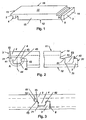
- FIG. 1 an inventive panel element is shown schematically in an oblique view.
- the panel element according to the invention has a payload side 11, a counter-pull 12 opposite the payload side 11, a first side 13 with a spring 2 and a second side 14 opposite the first side 13 with a groove 3 of the same design.
- the spring 2 has a connecting element 4, which extends substantially perpendicular to the useful side 11 and whose cross-section has a first flank 41 and a first flank 41 opposite second flank 42, wherein the cross section of the connecting element 4 a perpendicular to the useful side 11 extending center line 44 has.
- the panel element according to the invention according to FIG. 1 has a substantially rectangular shape. It may also be square or of another shape, e.g. rhombic, triangular, hexagonal, octagonal, oval or the like
- the first side 13 and the second side 14 may be end faces (in this case interfaces transverse to the fiber path) of the panel element according to the invention. It can be provided that on the longitudinal sides 15, 16 each have a spring 2 and / or a groove 3 is provided, wherein the spring on one of the longitudinal sides 15, 16 may be configured differently than the spring 2 on the first side 13th In other embodiments of the panel element according to the invention it is provided that the spring 2 is formed on one of the longitudinal sides.
- Fig. 2 the cross section of an embodiment of the panel element according to the invention is shown, wherein the cross section is normal to the longitudinal direction of the spring 2. Seen in the direction of the useful side 11, in a first portion 45 of the connecting element 4, the inclination of the first flank 41 and the second flank 42 in each case from the center line 44 to the outside. In a second portion 46 has - as seen in the direction of the Nutzseite - the inclination of the first edge 41 from the center line 44 to the outside and the inclination of the second edge 42 to the center line 44, wherein the distance perpendicular to the center line between the first edge 41 and the second edge 42 is reduced.
- FIG. 4 the detail A of the cross-sectional view of FIG. 2 is shown, wherein the first portion 45 and the second portion 46 are highlighted by dashed lines.
- the inclination of the first flank 41 and the inclination of the second flank 42 are each substantially constant in the first section 45.
- the connecting element 4 has in the first Section 45, the shape of a classic dovetail with extending from a root portion 43 of the connecting element 4 flanks 41,42
- the first edge 41 also has a substantially constant inclination in the second portion 46, which is equal to the inclination of the first flank 41 in the first section 45, wherein the execution of a substantially constant inclination of the first flank 41 in the first section 45 and the second portion 46 and an optionally between these sections 45,46 area is easy to produce.
- the second flank 42 may be rounded in the second section 46, whereby a simple insertion of the second flank 42 of the spring 2 is ensured in the groove 3.
- the groove 3 has a connecting element 4 of the same design recess 5. In the groove 3 '46 voltage peaks due to notch effect are avoided in the rounded version of the second edge 42 in the second section.
- the tongue and groove connection of the embodiment of the panel element according to the invention shown in FIG. 2 is shown in Fig. 3.
- the spring 2 is moved perpendicular to the payload side against the groove 3 and / or tilted, wherein first the first edge 41 contacts a first edge 51 of the recess 5.
- a further movement occurs at the first edge 41 and the first edge 51 a deformation, wherein a first locking resistance must be overcome, which has its maximum value upon impact of the first edge 41 on the first edge 51.
- the second edge 42 does not touch the first edge 51 opposite the second edge 52 of the recess, which is why on the second edge 42 in this position, no latching resistance occurs.
- the second flank 42 After overcoming the maximum of the first latching resistance at the first edge 41, the second flank 42 approaches the second edge 52 during further movement until it touches it and a second latching resistance occurs at the second flank 42, the maximum of the second latching resistor does not occur simultaneously with the maximum of the first latching resistance, so that the force required to produce the tongue and groove connection is less than the sum of the maximum of the first latching resistor and the maximum of the second latching resistor.
- the force required to produce the tongue and groove connection which is directed transversely to the laying plane, can be applied by means of hammer blow on a pad.
- the arrangement of the panels according to the invention to each other is backlash-free, seamless and non-destructive releasable again.
- a reference surface 53 running parallel to the useful surface 11 is formed on the upper side of the edge 51, which has the same vertical distance with respect to the useful surface 11 as the opposite, formed on the spring-side end face 13, to the effective surface 11 parallel, second reference surface 22, which is arranged in the installed state on the underside of the spring 2 between the end face 21 and the flank 41.
- the spring 2 rests on the edge 53.
- a first contact point 61 is formed on the first flank 41 and a second contact point 62 on the second flank 42, which are indicated in FIG. 3 by a respective point.
- the transferable from one of the contact point 61, 62 force perpendicular to the effective area 11 is proportional to the area of the contact point 61, 62 and the inclination of the edge 41, 42 of the connecting element 4 on the side of the contact point 61, 62. Since the surface of the contact point 61 large As the contact point 62 can be executed, it appears advantageous if the first edge 41 in the first section 45 has a lower inclination than the second edge 42, whereby the amount of perpendicular to the effective surface 11 transferable forces of the contact points 61, 62 are mutually approximated can.
- the contact point 61 essentially counteracts this movement.
- the first edge 41 is arranged on the side facing away from the panel element of the connecting element 4, since the first contact point 61 may be formed larger than the second contact point 62 and therefore lower voltages occur at a predetermined stress.
- the contact point also counteracts a climate-induced dimensional change of the spring.
- a first glue channel 71 may be formed in the region of the depression 5 facing the counter-pull 12.
- the glue channel 71 extends over the entire width of the cross section of the recess 5.
- a portion of the recess 5 can be made recessed and form the glue channel 71.
- the groove 3 may have a further glue channel 72, wherein the further glue channel 72 is arranged in the connected state of the tongue and groove connection adjacent to the end face 21 of the spring 2.
- An adhesion of the spring 2 with the groove 3 in the region of the further glue channel 72 causes a particularly high resistance to climate-related dimensional change of the end face 21 of the spring 2. Furthermore, the penetration of moisture into the region of the connecting element 4 is prevented.
- a long shelf life of the panel element according to the invention and of the compound according to the invention can be achieved if the sides 13, 14, 15, 16 are at least partially treated with a hydrophobic agent, in particular sprayed, coated or the like.
Landscapes
- Engineering & Computer Science (AREA)
- Architecture (AREA)
- Life Sciences & Earth Sciences (AREA)
- Wood Science & Technology (AREA)
- Civil Engineering (AREA)
- Structural Engineering (AREA)
- Floor Finish (AREA)
- Joining Of Building Structures In Genera (AREA)
- Connection Of Plates (AREA)
- Finishing Walls (AREA)
- Coupling Device And Connection With Printed Circuit (AREA)
Claims (10)
- Elément de panneau comprenant une paroi d'utilisation (11), une paroi opposée (12) en vis-à-vis de la paroi d'utilisation (11), un premier voile (13) muni d'une languette (2), un second voile (14) disposé en vis-à-vis du premier voile (13) avec une rainure (3) réalisée en même temps que la languette (2), la languette (2) présentant un élément de liaison (4), lequel s'étendant verticalement pour l'essentiel par rapport à la paroi d'utilisation (11), et dont la coupe présente un premier flanc (41) et un second flanc (42) en vis-à-vis du premier flanc (41), et où la coupe de l'élément de liaison (4) présente une ligne médiane (44) s'étendant verticalement par rapport à la paroi d'utilisation, et -dans la direction représentée de la paroi d'utilisation (11)- dans un premier tronçon (45) de l'élément de liaison (4) l'inclinaison du premier flanc (41) et du second flanc (42) est dirigée vers l'extérieur par rapport à la ligne médiane (44) et dans un second tronçon (46) l'inclinaison du premier tronçon (41) est dirigée vers l'extérieur par rapport à la ligne médiane (44) et l'inclinaison du second flanc (42) vers la ligne médiane (44) et où la distance à la verticale de la ligne médiane (44) entre le premier flanc (41) et le second flanc (42) se réduit, caractérisé en ce que le premier flanc (41) est positionné au niveau de la paroi adjacente de l'élément de panneau de l'élément de liaison (4).
- Elément de panneau selon la revendication 1, caractérisé en ce que l'inclinaison du premier flanc (41) et l'inclinaison du second flanc (42) dans le premier tronçon (45) est chacune pour l'essentiel constant.
- Elément de panneau selon la revendication 2, caractérisé en ce que le premier flanc (41) dans le premier tronçon (45) présente une faible inclinaison comme le second flanc (42).
- Elément de panneau selon la revendication 2 ou 3, caractérisé en ce que l'inclinaison du premier flanc (41) dans le second tronçon (46) est pour l'essentiel constante et est aussi grande que l'inclinaison du premier flanc (41) dans le premier tronçon (45).
- Elément de panneau selon l'une des revendications 1 à 4, caractérisé en ce que le second flanc (42) dans le second tronçon (46) est réalisé de manière arrondie.
- Elément de panneau selon l'une des revendications 1 à 5, caractérisé en ce que la rainure (3) présente un creux (5) réalisé de manière équivalente à l'élément de liaison (4) et forme dans la position de liaison de la rainure (3) et de la languette (2) d'un autre élément de panneau identique une première position de contact (61) au niveau du premier flanc (41) de l'élément de liaison (4) et une seconde position de contact (62) au niveau du second flanc (42) de l'élément de liaison (4).
- Elément de panneau selon la revendication 6, caractérisé en ce qu'un canal pour colle (71) est formé dans le côté opposé (12) à proximité immédiate du creux (5).
- Elément de panneau selon la revendication 7, caractérisé en ce que la rainure (3) comporte un autre canal pour colle (72), où le canal pour colle (72) est disposé à l'état lié de la rainure (3) et de la languette (2) d'un autre élément de panneau identique adjacent à la partie frontale (21) de la languette (2) de l'autre élément de panneau identique.
- Elément de panneau selon l'une des revendications 6 à 8, caractérisé en ce que -à l'état lié de la rainure (3) avec la languette (2) d'un autre élément de panneau identique- une fente (8) est prévue au voisinage de la partie frontale (31) de la rainure (3) entre la languette (2) de l'autre élément de panneau identique et la rainure (3) s'étendant de manière continue jusqu'à la seconde surface de contact (62).
- Elément de panneau selon l'une des revendications 1 à 9, caractérisé en ce que les parois (13, 14, 15, 16) sont traitées au moins au niveau sectoriel avec un moyen hydrophobe en particulier par pulvérisation, badigeonnage ou équivalent.
Applications Claiming Priority (3)
| Application Number | Priority Date | Filing Date | Title |
|---|---|---|---|
| AT9852002 | 2002-07-02 | ||
| AT0098502A AT414252B (de) | 2002-07-02 | 2002-07-02 | Paneelelement sowie verbindungssystem für paneelelemente |
| PCT/EP2003/006474 WO2004005648A1 (fr) | 2002-07-02 | 2003-06-18 | Element panneau et systeme de connexion d'elements panneaux |
Publications (2)
| Publication Number | Publication Date |
|---|---|
| EP1518031A1 EP1518031A1 (fr) | 2005-03-30 |
| EP1518031B1 true EP1518031B1 (fr) | 2007-08-29 |
Family
ID=30004238
Family Applications (1)
| Application Number | Title | Priority Date | Filing Date |
|---|---|---|---|
| EP03735650A Expired - Lifetime EP1518031B1 (fr) | 2002-07-02 | 2003-06-18 | Panneau, en particulier panneau de parquet ou panneau de sol stratifié |
Country Status (8)
| Country | Link |
|---|---|
| US (1) | US7543418B2 (fr) |
| EP (1) | EP1518031B1 (fr) |
| CN (1) | CN100378280C (fr) |
| AT (2) | AT414252B (fr) |
| AU (1) | AU2003237961A1 (fr) |
| DE (1) | DE50308071D1 (fr) |
| ES (1) | ES2292975T3 (fr) |
| WO (1) | WO2004005648A1 (fr) |
Cited By (1)
| Publication number | Priority date | Publication date | Assignee | Title |
|---|---|---|---|---|
| DE102012214379A1 (de) | 2012-08-13 | 2014-02-13 | Weitzer Holding Gmbh | Untergrundbelag mit integrierter Sensorvorrichtung |
Families Citing this family (39)
| Publication number | Priority date | Publication date | Assignee | Title |
|---|---|---|---|---|
| BE1014640A6 (nl) * | 2002-02-14 | 2004-02-03 | Houthandel Wouters N V | Haakse tand-en groefverbinding. |
| US20040206036A1 (en) | 2003-02-24 | 2004-10-21 | Valinge Aluminium Ab | Floorboard and method for manufacturing thereof |
| US7600354B2 (en) * | 2003-07-02 | 2009-10-13 | Kaindl Flooring Gmbh | Panels comprising interlocking snap-in profiles |
| US7886497B2 (en) | 2003-12-02 | 2011-02-15 | Valinge Innovation Ab | Floorboard, system and method for forming a flooring, and a flooring formed thereof |
| US7748177B2 (en) | 2004-02-25 | 2010-07-06 | Connor Sport Court International, Inc. | Modular tile with controlled deflection |
| DE102004012582A1 (de) * | 2004-03-12 | 2005-10-06 | Hülsta-Werke Hüls Gmbh & Co. Kg | Paneelelement |
| US8407951B2 (en) | 2004-10-06 | 2013-04-02 | Connor Sport Court International, Llc | Modular synthetic floor tile configured for enhanced performance |
| US8397466B2 (en) | 2004-10-06 | 2013-03-19 | Connor Sport Court International, Llc | Tile with multiple-level surface |
| USD656250S1 (en) | 2005-03-11 | 2012-03-20 | Connor Sport Court International, Llc | Tile with wide mouth coupling |
| DE102005059540A1 (de) * | 2005-08-19 | 2007-06-14 | Bauer, Jörg R. | Lösbar aneinander zu befestigende, flächige Bauteile, sowie Bauteil |
| SE530653C2 (sv) | 2006-01-12 | 2008-07-29 | Vaelinge Innovation Ab | Fuktsäker golvskiva samt golv med ett elastiskt ytskikt omfattande ett dekorativt spår |
| US7490443B1 (en) * | 2006-03-01 | 2009-02-17 | Bike Track, Inc. | Modular flooring system |
| US7900416B1 (en) | 2006-03-30 | 2011-03-08 | Connor Sport Court International, Inc. | Floor tile with load bearing lattice |
| US20090301021A1 (en) * | 2008-06-09 | 2009-12-10 | Jenny Carl J | Interlocking panel system |
| US8793959B2 (en) * | 2009-05-08 | 2014-08-05 | Novalis Holdings Limited | Overlap system for a flooring system |
| US8365499B2 (en) * | 2009-09-04 | 2013-02-05 | Valinge Innovation Ab | Resilient floor |
| RU2535572C2 (ru) | 2009-09-04 | 2014-12-20 | Велинге Инновейшн Аб | Способ сборки эластичных паркетных досок, которые снабжены механической блокирующей системой |
| US11725395B2 (en) | 2009-09-04 | 2023-08-15 | Välinge Innovation AB | Resilient floor |
| TW201122191A (en) * | 2009-12-30 | 2011-07-01 | Axuntek Solar Energy | Solar tile structure and combination thereof |
| US8881482B2 (en) | 2010-01-22 | 2014-11-11 | Connor Sport Court International, Llc | Modular flooring system |
| US8683769B2 (en) | 2010-01-22 | 2014-04-01 | Connor Sport Court International, Llc | Modular sub-flooring system |
| US20130255174A1 (en) * | 2010-01-29 | 2013-10-03 | Royal Mouldings, Limited | Siding joinery |
| US8402707B2 (en) * | 2010-01-29 | 2013-03-26 | Royal Group Inc. | Interlocking panel system |
| US8505256B2 (en) | 2010-01-29 | 2013-08-13 | Connor Sport Court International, Llc | Synthetic floor tile having partially-compliant support structure |
| US8393094B1 (en) * | 2010-02-11 | 2013-03-12 | Brian Legenza | Snow removal assembly and method |
| US8806832B2 (en) | 2011-03-18 | 2014-08-19 | Inotec Global Limited | Vertical joint system and associated surface covering system |
| RU2672903C2 (ru) | 2011-08-29 | 2018-11-20 | Сералок Инновейшн Аб | Механическая блокировочная система для панелей пола |
| EP2895667B1 (fr) | 2012-08-27 | 2019-12-04 | Pergo (Europe) AB | Panneau |
| AU2014263243B2 (en) | 2013-03-25 | 2017-12-21 | Valinge Innovation Ab | Floorboards provided with a mechanical locking system and a method to produce such a locking system |
| CA153725S (en) * | 2013-11-01 | 2014-08-26 | Groupe Isolofoam Inc | Insulation panel |
| WO2015070890A1 (fr) | 2013-11-12 | 2015-05-21 | Grigorij Wagner | Élément de revêtement de sol |
| ES2960221T3 (es) | 2014-07-16 | 2024-03-01 | Vaelinge Innovation Ab | Método para producir un lámina resistente al desgaste termoplástica |
| TWM505519U (zh) * | 2015-02-25 | 2015-07-21 | Yu-Yong Zheng | 拼裝地板塊 |
| US20160312476A1 (en) * | 2015-04-17 | 2016-10-27 | Commercial Interiors Manufacturing, Inc. | Wall Covering Systems And Wall Covering System Components |
| NL2019609B1 (en) * | 2017-09-22 | 2019-03-28 | Innovations4Flooring Holding N V | Panel and covering |
| FR3089534B1 (fr) * | 2018-12-07 | 2023-03-03 | Gerflor | Panneau a assemblage vertical pour la realisation d’un revêtement |
| AU2022218374A1 (en) * | 2021-02-08 | 2023-08-31 | James Hardie Technology Limited | An adhesive panel joint in a building section |
| MX2023015105A (es) * | 2021-06-23 | 2024-01-22 | Flooring Ind Ltd Sarl | Panel decorativo. |
| USD1057217S1 (en) * | 2022-08-19 | 2025-01-07 | Nexus Global Co., Ltd. | Floor panel |
Family Cites Families (30)
| Publication number | Priority date | Publication date | Assignee | Title |
|---|---|---|---|---|
| DK128860A (fr) * | 1966-05-12 | |||
| FR2278876A1 (fr) * | 1973-10-09 | 1976-02-13 | Choppe Roger | Procede d'assemblage de dalles divers pour revetement de sol |
| US4426820A (en) | 1979-04-24 | 1984-01-24 | Heinz Terbrack | Panel for a composite surface and a method of assembling same |
| DE8134756U1 (de) * | 1981-11-28 | 1982-05-19 | Traub, Eugen, 7101 Abstatt | "plattenfoermiges bauelement aus hartschaumkunststoffo.dgl., insbesondere zur waermeisolierung von dach- und wandflaechen von gebaeuden" |
| GB2256023A (en) * | 1991-05-18 | 1992-11-25 | Magnet Holdings Ltd | Joint |
| DE4242530C2 (de) | 1992-12-16 | 1996-09-12 | Walter Friedl | Bauelement für Wände, Decken oder Dächer von Bauwerken |
| SE9500810D0 (sv) * | 1995-03-07 | 1995-03-07 | Perstorp Flooring Ab | Golvplatta |
| BE1010487A6 (nl) | 1996-06-11 | 1998-10-06 | Unilin Beheer Bv | Vloerbekleding bestaande uit harde vloerpanelen en werkwijze voor het vervaardigen van dergelijke vloerpanelen. |
| US5797237A (en) * | 1997-02-28 | 1998-08-25 | Standard Plywoods, Incorporated | Flooring system |
| USD406360S (en) * | 1997-02-28 | 1999-03-02 | Standard Plywoods, Incorporated | Flooring member |
| US6345481B1 (en) | 1997-11-25 | 2002-02-12 | Premark Rwp Holdings, Inc. | Article with interlocking edges and covering product prepared therefrom |
| SE513189C2 (sv) | 1998-10-06 | 2000-07-24 | Perstorp Flooring Ab | Vertikalmonterbart golvbeläggningsmaterial innefattande skivformiga golvelement vilka sammanfogas med hjälp av separata sammanfogningsprofiler |
| SE515789C2 (sv) | 1999-02-10 | 2001-10-08 | Perstorp Flooring Ab | Golvbeläggningsmaterial innefattande golvelement vilka är avsedda att sammanfogas vertikalt |
| DE19851200C1 (de) * | 1998-11-06 | 2000-03-30 | Kronotex Gmbh Holz Und Kunstha | Fußbodenpaneele |
| FR2785633B1 (fr) * | 1998-11-09 | 2001-02-09 | Valerie Roy | Panneau de recouvrement pour parquet, lambris ou analogue |
| IT1311220B1 (it) | 1999-04-20 | 2002-03-04 | Patt Srl | Pavimento a doghe e metodo per la sua posa in opera |
| DE19929896B4 (de) | 1999-06-30 | 2009-07-30 | Akzenta Paneele + Profile Gmbh | Befestigungssystem für Paneele |
| EP1243721A3 (fr) * | 1999-06-30 | 2003-07-09 | Akzenta Paneele + Profile GmbH | Revêtement de sol, panneau et dispositif de fixation pour panneaux |
| DE29911462U1 (de) | 1999-07-02 | 1999-11-18 | Akzenta Paneele & Profile Gmbh | Befestigungssystem für Paneele |
| DE19933343A1 (de) | 1999-07-16 | 2001-02-01 | Ledermann & Co | Verfahren zum Verbinden von Platten und Verbindungsanordnung |
| DE10001076C1 (de) * | 2000-01-13 | 2001-10-04 | Huelsta Werke Huels Kg | Paneelelement |
| DE10008166C2 (de) | 2000-02-23 | 2003-04-24 | Kronotec Ag | Fussbodenpaneel |
| TR200202114T2 (tr) * | 2000-03-07 | 2003-01-21 | E.F.P. Floor Products Fussb�den GmbH | Mekanik panel bağlantısı |
| DE20008708U1 (de) | 2000-05-16 | 2000-09-14 | Kronospan Technical Co. Ltd., Nikosia | Paneele mit Kupplungsmitteln |
| DE10031639C2 (de) | 2000-06-29 | 2002-08-14 | Hw Ind Gmbh & Co Kg | Fussbodenplatte |
| CN2447458Y (zh) * | 2000-10-02 | 2001-09-12 | 爱家强化木地板(深圳)有限公司 | 卡扣型强化木地板 |
| ITTV20000124A1 (it) | 2000-10-09 | 2002-04-09 | Skema Srl | Struttura di elemento di rivestimento particolarmente per la pavimentazione a parchetti |
| EA004339B1 (ru) * | 2000-10-10 | 2004-04-29 | Таркетт Соммер С.А. | Самосцепляющиеся планки с пазами и выступами для образования пола и способ их механической обработки |
| DE10120062B4 (de) | 2001-04-24 | 2008-03-20 | Kronotec Ag | Fussbodenpaneel |
| DE20203311U1 (de) | 2002-03-01 | 2002-05-08 | hülsta-werke Hüls GmbH & Co. KG, 48703 Stadtlohn | Paneelelement |
-
2002
- 2002-07-02 AT AT0098502A patent/AT414252B/de not_active IP Right Cessation
-
2003
- 2003-06-18 ES ES03735650T patent/ES2292975T3/es not_active Expired - Lifetime
- 2003-06-18 AT AT03735650T patent/ATE371783T1/de not_active IP Right Cessation
- 2003-06-18 WO PCT/EP2003/006474 patent/WO2004005648A1/fr not_active Ceased
- 2003-06-18 EP EP03735650A patent/EP1518031B1/fr not_active Expired - Lifetime
- 2003-06-18 DE DE50308071T patent/DE50308071D1/de not_active Expired - Lifetime
- 2003-06-18 US US10/520,038 patent/US7543418B2/en not_active Expired - Fee Related
- 2003-06-18 AU AU2003237961A patent/AU2003237961A1/en not_active Abandoned
- 2003-06-18 CN CNB038155893A patent/CN100378280C/zh not_active Expired - Fee Related
Non-Patent Citations (1)
| Title |
|---|
| None * |
Cited By (2)
| Publication number | Priority date | Publication date | Assignee | Title |
|---|---|---|---|---|
| DE102012214379A1 (de) | 2012-08-13 | 2014-02-13 | Weitzer Holding Gmbh | Untergrundbelag mit integrierter Sensorvorrichtung |
| DE102012214379B4 (de) | 2012-08-13 | 2021-10-21 | Weitzer Holding Gmbh | Untergrundbelag mit integrierter Sensorvorrichtung |
Also Published As
| Publication number | Publication date |
|---|---|
| DE50308071D1 (de) | 2007-10-11 |
| ES2292975T3 (es) | 2008-03-16 |
| CN100378280C (zh) | 2008-04-02 |
| CN1665998A (zh) | 2005-09-07 |
| ATE371783T1 (de) | 2007-09-15 |
| US7543418B2 (en) | 2009-06-09 |
| AU2003237961A1 (en) | 2004-01-23 |
| AT414252B (de) | 2006-10-15 |
| US20050204676A1 (en) | 2005-09-22 |
| EP1518031A1 (fr) | 2005-03-30 |
| WO2004005648A1 (fr) | 2004-01-15 |
| ATA9852002A (de) | 2006-01-15 |
Similar Documents
| Publication | Publication Date | Title |
|---|---|---|
| EP1518031B1 (fr) | Panneau, en particulier panneau de parquet ou panneau de sol stratifié | |
| EP1282752B1 (fr) | Panneaux comportant des moyens d'accouplement | |
| EP2057327B1 (fr) | Panneau, notamment panneau de sol | |
| DE10243196B4 (de) | Paneele mit Verbindungsklammer | |
| EP1766154B1 (fr) | Panneaux de mur ou de plafond a positionnement multiple | |
| WO2001002670A1 (fr) | Panneau et dispositif de fixation pour panneaux | |
| EP1476615A1 (fr) | Panneau, en particulier panneau de revetement de sol | |
| EP0728507A2 (fr) | Jeu de construction | |
| EP2446097A1 (fr) | Dispositif de profilé pour plancher | |
| EP1513994B1 (fr) | Panneau, en particulier panneau de parquet ou panneau de sol stratifié | |
| DE3743192A1 (de) | Befestigungssystem fuer abdeckungen | |
| DE102020123839B4 (de) | Verbindungselement für ein Möbelstück, Stecksystem mit einem solchen Verbindungselement und ein Verfahren zur Montage eines Möbelstücks | |
| AT5921U2 (de) | Paneelelement sowie verbindungssystem für paneelelemente | |
| EP4141193A1 (fr) | Panneau, en particulier panneau de sol, ayant pour fonction l'étanchéité | |
| DE202008006250U1 (de) | Verbindung | |
| DE9307503U1 (de) | Aus Hohlprofilen sowie aus Eckverbindern hergestellter Rahmen | |
| DE20200268U1 (de) | Paneelelement | |
| DE19925867A1 (de) | Verbindungssystem | |
| AT396565B (de) | Verfahren zum zusammenbau zweier nicht koplanarer holzbauteile | |
| EP0111185A2 (fr) | Cadre, en particulier pour une cloison de douche | |
| EP0104533B1 (fr) | Dispositif de connexion de préférence détachable pour éléments de construction | |
| DE202006015942U1 (de) | Paneelelement für Bodenbeläge | |
| EP2662578B1 (fr) | Cheville plate et liaison en utilisant une cheville plate | |
| EP4385849A1 (fr) | Dispositif de guidage pour une transition entre une première partie de véhicule et une seconde partie de véhicule d'un véhicule à plusieurs parties et véhicule équipé d'un tel dispositif de guidage | |
| EP0887487A2 (fr) | Système de fixation pour poignée |
Legal Events
| Date | Code | Title | Description |
|---|---|---|---|
| PUAI | Public reference made under article 153(3) epc to a published international application that has entered the european phase |
Free format text: ORIGINAL CODE: 0009012 |
|
| 17P | Request for examination filed |
Effective date: 20041117 |
|
| AK | Designated contracting states |
Kind code of ref document: A1 Designated state(s): AT BE BG CH CY CZ DE DK EE ES FI FR GB GR HU IE IT LI LU MC NL PT RO SE SI SK TR |
|
| AX | Request for extension of the european patent |
Extension state: AL LT LV MK |
|
| DAX | Request for extension of the european patent (deleted) | ||
| GRAP | Despatch of communication of intention to grant a patent |
Free format text: ORIGINAL CODE: EPIDOSNIGR1 |
|
| RTI1 | Title (correction) |
Free format text: PANEL, IN PARTICULAR PARQUET FLOORBOARD OR LAMINATE FLOORBOARD |
|
| GRAS | Grant fee paid |
Free format text: ORIGINAL CODE: EPIDOSNIGR3 |
|
| GRAA | (expected) grant |
Free format text: ORIGINAL CODE: 0009210 |
|
| AK | Designated contracting states |
Kind code of ref document: B1 Designated state(s): AT BE BG CH CY CZ DE DK EE ES FI FR GB GR HU IE IT LI LU MC NL PT RO SE SI SK TR |
|
| REG | Reference to a national code |
Ref country code: GB Ref legal event code: FG4D Free format text: NOT ENGLISH |
|
| REG | Reference to a national code |
Ref country code: CH Ref legal event code: EP |
|
| REG | Reference to a national code |
Ref country code: IE Ref legal event code: FG4D Free format text: LANGUAGE OF EP DOCUMENT: GERMAN |
|
| REF | Corresponds to: |
Ref document number: 50308071 Country of ref document: DE Date of ref document: 20071011 Kind code of ref document: P |
|
| REG | Reference to a national code |
Ref country code: SE Ref legal event code: TRGR |
|
| PG25 | Lapsed in a contracting state [announced via postgrant information from national office to epo] |
Ref country code: FI Free format text: LAPSE BECAUSE OF FAILURE TO SUBMIT A TRANSLATION OF THE DESCRIPTION OR TO PAY THE FEE WITHIN THE PRESCRIBED TIME-LIMIT Effective date: 20070829 Ref country code: NL Free format text: LAPSE BECAUSE OF FAILURE TO SUBMIT A TRANSLATION OF THE DESCRIPTION OR TO PAY THE FEE WITHIN THE PRESCRIBED TIME-LIMIT Effective date: 20070829 |
|
| REG | Reference to a national code |
Ref country code: CH Ref legal event code: NV Representative=s name: ING. MARCO ZARDI C/O M. ZARDI & CO. S.A. |
|
| NLV1 | Nl: lapsed or annulled due to failure to fulfill the requirements of art. 29p and 29m of the patents act | ||
| REG | Reference to a national code |
Ref country code: ES Ref legal event code: FG2A Ref document number: 2292975 Country of ref document: ES Kind code of ref document: T3 |
|
| ET | Fr: translation filed | ||
| GBV | Gb: ep patent (uk) treated as always having been void in accordance with gb section 77(7)/1977 [no translation filed] |
Effective date: 20070829 |
|
| REG | Reference to a national code |
Ref country code: IE Ref legal event code: FD4D |
|
| PG25 | Lapsed in a contracting state [announced via postgrant information from national office to epo] |
Ref country code: DK Free format text: LAPSE BECAUSE OF FAILURE TO SUBMIT A TRANSLATION OF THE DESCRIPTION OR TO PAY THE FEE WITHIN THE PRESCRIBED TIME-LIMIT Effective date: 20070829 Ref country code: GR Free format text: LAPSE BECAUSE OF FAILURE TO SUBMIT A TRANSLATION OF THE DESCRIPTION OR TO PAY THE FEE WITHIN THE PRESCRIBED TIME-LIMIT Effective date: 20071130 |
|
| PG25 | Lapsed in a contracting state [announced via postgrant information from national office to epo] |
Ref country code: CZ Free format text: LAPSE BECAUSE OF FAILURE TO SUBMIT A TRANSLATION OF THE DESCRIPTION OR TO PAY THE FEE WITHIN THE PRESCRIBED TIME-LIMIT Effective date: 20070829 Ref country code: GB Free format text: LAPSE BECAUSE OF FAILURE TO SUBMIT A TRANSLATION OF THE DESCRIPTION OR TO PAY THE FEE WITHIN THE PRESCRIBED TIME-LIMIT Effective date: 20070829 Ref country code: IE Free format text: LAPSE BECAUSE OF FAILURE TO SUBMIT A TRANSLATION OF THE DESCRIPTION OR TO PAY THE FEE WITHIN THE PRESCRIBED TIME-LIMIT Effective date: 20070829 Ref country code: PT Free format text: LAPSE BECAUSE OF FAILURE TO SUBMIT A TRANSLATION OF THE DESCRIPTION OR TO PAY THE FEE WITHIN THE PRESCRIBED TIME-LIMIT Effective date: 20080129 Ref country code: SK Free format text: LAPSE BECAUSE OF FAILURE TO SUBMIT A TRANSLATION OF THE DESCRIPTION OR TO PAY THE FEE WITHIN THE PRESCRIBED TIME-LIMIT Effective date: 20070829 |
|
| PG25 | Lapsed in a contracting state [announced via postgrant information from national office to epo] |
Ref country code: RO Free format text: LAPSE BECAUSE OF FAILURE TO SUBMIT A TRANSLATION OF THE DESCRIPTION OR TO PAY THE FEE WITHIN THE PRESCRIBED TIME-LIMIT Effective date: 20070829 |
|
| PLBE | No opposition filed within time limit |
Free format text: ORIGINAL CODE: 0009261 |
|
| STAA | Information on the status of an ep patent application or granted ep patent |
Free format text: STATUS: NO OPPOSITION FILED WITHIN TIME LIMIT |
|
| 26N | No opposition filed |
Effective date: 20080530 |
|
| BERE | Be: lapsed |
Owner name: WEITZER PARKETT GMBH & CO. KG Effective date: 20080630 |
|
| PG25 | Lapsed in a contracting state [announced via postgrant information from national office to epo] |
Ref country code: MC Free format text: LAPSE BECAUSE OF NON-PAYMENT OF DUE FEES Effective date: 20080630 |
|
| PG25 | Lapsed in a contracting state [announced via postgrant information from national office to epo] |
Ref country code: BE Free format text: LAPSE BECAUSE OF NON-PAYMENT OF DUE FEES Effective date: 20080630 |
|
| PG25 | Lapsed in a contracting state [announced via postgrant information from national office to epo] |
Ref country code: EE Free format text: LAPSE BECAUSE OF FAILURE TO SUBMIT A TRANSLATION OF THE DESCRIPTION OR TO PAY THE FEE WITHIN THE PRESCRIBED TIME-LIMIT Effective date: 20070829 |
|
| PG25 | Lapsed in a contracting state [announced via postgrant information from national office to epo] |
Ref country code: SI Free format text: LAPSE BECAUSE OF FAILURE TO SUBMIT A TRANSLATION OF THE DESCRIPTION OR TO PAY THE FEE WITHIN THE PRESCRIBED TIME-LIMIT Effective date: 20070829 |
|
| PG25 | Lapsed in a contracting state [announced via postgrant information from national office to epo] |
Ref country code: CY Free format text: LAPSE BECAUSE OF FAILURE TO SUBMIT A TRANSLATION OF THE DESCRIPTION OR TO PAY THE FEE WITHIN THE PRESCRIBED TIME-LIMIT Effective date: 20070829 |
|
| PG25 | Lapsed in a contracting state [announced via postgrant information from national office to epo] |
Ref country code: AT Free format text: LAPSE BECAUSE OF NON-PAYMENT OF DUE FEES Effective date: 20080618 Ref country code: BG Free format text: LAPSE BECAUSE OF FAILURE TO SUBMIT A TRANSLATION OF THE DESCRIPTION OR TO PAY THE FEE WITHIN THE PRESCRIBED TIME-LIMIT Effective date: 20071129 |
|
| PG25 | Lapsed in a contracting state [announced via postgrant information from national office to epo] |
Ref country code: HU Free format text: LAPSE BECAUSE OF FAILURE TO SUBMIT A TRANSLATION OF THE DESCRIPTION OR TO PAY THE FEE WITHIN THE PRESCRIBED TIME-LIMIT Effective date: 20080301 Ref country code: LU Free format text: LAPSE BECAUSE OF NON-PAYMENT OF DUE FEES Effective date: 20080618 |
|
| PG25 | Lapsed in a contracting state [announced via postgrant information from national office to epo] |
Ref country code: TR Free format text: LAPSE BECAUSE OF FAILURE TO SUBMIT A TRANSLATION OF THE DESCRIPTION OR TO PAY THE FEE WITHIN THE PRESCRIBED TIME-LIMIT Effective date: 20070829 |
|
| REG | Reference to a national code |
Ref country code: DE Ref legal event code: R082 Ref document number: 50308071 Country of ref document: DE Representative=s name: DILG HAEUSLER SCHINDELMANN PATENTANWALTSGESELL, DE |
|
| PGFP | Annual fee paid to national office [announced via postgrant information from national office to epo] |
Ref country code: ES Payment date: 20120725 Year of fee payment: 10 |
|
| PGFP | Annual fee paid to national office [announced via postgrant information from national office to epo] |
Ref country code: CH Payment date: 20130612 Year of fee payment: 11 Ref country code: SE Payment date: 20130625 Year of fee payment: 11 |
|
| PGFP | Annual fee paid to national office [announced via postgrant information from national office to epo] |
Ref country code: IT Payment date: 20130620 Year of fee payment: 11 |
|
| PGFP | Annual fee paid to national office [announced via postgrant information from national office to epo] |
Ref country code: FR Payment date: 20130724 Year of fee payment: 11 |
|
| PG25 | Lapsed in a contracting state [announced via postgrant information from national office to epo] |
Ref country code: SE Free format text: LAPSE BECAUSE OF NON-PAYMENT OF DUE FEES Effective date: 20140619 |
|
| REG | Reference to a national code |
Ref country code: CH Ref legal event code: PL |
|
| REG | Reference to a national code |
Ref country code: SE Ref legal event code: EUG |
|
| REG | Reference to a national code |
Ref country code: FR Ref legal event code: ST Effective date: 20150227 |
|
| PG25 | Lapsed in a contracting state [announced via postgrant information from national office to epo] |
Ref country code: LI Free format text: LAPSE BECAUSE OF NON-PAYMENT OF DUE FEES Effective date: 20140630 Ref country code: IT Free format text: LAPSE BECAUSE OF NON-PAYMENT OF DUE FEES Effective date: 20140618 Ref country code: CH Free format text: LAPSE BECAUSE OF NON-PAYMENT OF DUE FEES Effective date: 20140630 |
|
| PG25 | Lapsed in a contracting state [announced via postgrant information from national office to epo] |
Ref country code: FR Free format text: LAPSE BECAUSE OF NON-PAYMENT OF DUE FEES Effective date: 20140630 |
|
| REG | Reference to a national code |
Ref country code: ES Ref legal event code: FD2A Effective date: 20150724 |
|
| PG25 | Lapsed in a contracting state [announced via postgrant information from national office to epo] |
Ref country code: ES Free format text: LAPSE BECAUSE OF NON-PAYMENT OF DUE FEES Effective date: 20140619 |
|
| PGFP | Annual fee paid to national office [announced via postgrant information from national office to epo] |
Ref country code: DE Payment date: 20180627 Year of fee payment: 16 |
|
| REG | Reference to a national code |
Ref country code: DE Ref legal event code: R119 Ref document number: 50308071 Country of ref document: DE |
|
| PG25 | Lapsed in a contracting state [announced via postgrant information from national office to epo] |
Ref country code: DE Free format text: LAPSE BECAUSE OF NON-PAYMENT OF DUE FEES Effective date: 20200101 |
|
| P01 | Opt-out of the competence of the unified patent court (upc) registered |
Effective date: 20230525 |