EP1517416B1 - Zündkerze - Google Patents
Zündkerze Download PDFInfo
- Publication number
- EP1517416B1 EP1517416B1 EP04019123A EP04019123A EP1517416B1 EP 1517416 B1 EP1517416 B1 EP 1517416B1 EP 04019123 A EP04019123 A EP 04019123A EP 04019123 A EP04019123 A EP 04019123A EP 1517416 B1 EP1517416 B1 EP 1517416B1
- Authority
- EP
- European Patent Office
- Prior art keywords
- ground electrode
- spark plug
- electrode carrier
- carrier casing
- combustion chamber
- Prior art date
- Legal status (The legal status is an assumption and is not a legal conclusion. Google has not performed a legal analysis and makes no representation as to the accuracy of the status listed.)
- Revoked
Links
- 238000002485 combustion reaction Methods 0.000 claims description 25
- 239000000463 material Substances 0.000 claims description 17
- PXHVJJICTQNCMI-UHFFFAOYSA-N Nickel Chemical compound [Ni] PXHVJJICTQNCMI-UHFFFAOYSA-N 0.000 claims description 8
- 229910052759 nickel Inorganic materials 0.000 claims description 4
- 229910045601 alloy Inorganic materials 0.000 claims description 3
- 239000000956 alloy Substances 0.000 claims description 3
- 229910000623 nickel–chromium alloy Inorganic materials 0.000 claims description 3
- VYZAMTAEIAYCRO-UHFFFAOYSA-N Chromium Chemical compound [Cr] VYZAMTAEIAYCRO-UHFFFAOYSA-N 0.000 claims description 2
- RYGMFSIKBFXOCR-UHFFFAOYSA-N Copper Chemical compound [Cu] RYGMFSIKBFXOCR-UHFFFAOYSA-N 0.000 claims description 2
- RTAQQCXQSZGOHL-UHFFFAOYSA-N Titanium Chemical compound [Ti] RTAQQCXQSZGOHL-UHFFFAOYSA-N 0.000 claims description 2
- 229910052782 aluminium Inorganic materials 0.000 claims description 2
- XAGFODPZIPBFFR-UHFFFAOYSA-N aluminium Chemical compound [Al] XAGFODPZIPBFFR-UHFFFAOYSA-N 0.000 claims description 2
- 229910052804 chromium Inorganic materials 0.000 claims description 2
- 239000011651 chromium Substances 0.000 claims description 2
- 229910017052 cobalt Inorganic materials 0.000 claims description 2
- 239000010941 cobalt Substances 0.000 claims description 2
- GUTLYIVDDKVIGB-UHFFFAOYSA-N cobalt atom Chemical compound [Co] GUTLYIVDDKVIGB-UHFFFAOYSA-N 0.000 claims description 2
- 229910052802 copper Inorganic materials 0.000 claims description 2
- 239000010949 copper Substances 0.000 claims description 2
- 229910052758 niobium Inorganic materials 0.000 claims description 2
- 239000010955 niobium Substances 0.000 claims description 2
- GUCVJGMIXFAOAE-UHFFFAOYSA-N niobium atom Chemical compound [Nb] GUCVJGMIXFAOAE-UHFFFAOYSA-N 0.000 claims description 2
- 239000010936 titanium Substances 0.000 claims description 2
- 229910052719 titanium Inorganic materials 0.000 claims description 2
- 238000009434 installation Methods 0.000 claims 6
- XEEYBQQBJWHFJM-UHFFFAOYSA-N Iron Chemical compound [Fe] XEEYBQQBJWHFJM-UHFFFAOYSA-N 0.000 claims 2
- ZOKXTWBITQBERF-UHFFFAOYSA-N Molybdenum Chemical compound [Mo] ZOKXTWBITQBERF-UHFFFAOYSA-N 0.000 claims 1
- 229910052742 iron Inorganic materials 0.000 claims 1
- 229910052750 molybdenum Inorganic materials 0.000 claims 1
- 239000011733 molybdenum Substances 0.000 claims 1
- WFKWXMTUELFFGS-UHFFFAOYSA-N tungsten Chemical compound [W] WFKWXMTUELFFGS-UHFFFAOYSA-N 0.000 claims 1
- 229910052721 tungsten Inorganic materials 0.000 claims 1
- 239000010937 tungsten Substances 0.000 claims 1
- 230000007797 corrosion Effects 0.000 description 4
- 238000005260 corrosion Methods 0.000 description 4
- 238000000034 method Methods 0.000 description 4
- 238000003466 welding Methods 0.000 description 4
- 239000012212 insulator Substances 0.000 description 3
- 239000000203 mixture Substances 0.000 description 2
- 239000010970 precious metal Substances 0.000 description 2
- 230000015572 biosynthetic process Effects 0.000 description 1
- 230000006378 damage Effects 0.000 description 1
- 230000002349 favourable effect Effects 0.000 description 1
- 230000017525 heat dissipation Effects 0.000 description 1
- 229910001055 inconels 600 Inorganic materials 0.000 description 1
- 238000004519 manufacturing process Methods 0.000 description 1
Images

Classifications
-
- H—ELECTRICITY
- H01—ELECTRIC ELEMENTS
- H01T—SPARK GAPS; OVERVOLTAGE ARRESTERS USING SPARK GAPS; SPARKING PLUGS; CORONA DEVICES; GENERATING IONS TO BE INTRODUCED INTO NON-ENCLOSED GASES
- H01T13/00—Sparking plugs
- H01T13/20—Sparking plugs characterised by features of the electrodes or insulation
- H01T13/32—Sparking plugs characterised by features of the electrodes or insulation characterised by features of the earthed electrode
-
- H—ELECTRICITY
- H01—ELECTRIC ELEMENTS
- H01T—SPARK GAPS; OVERVOLTAGE ARRESTERS USING SPARK GAPS; SPARKING PLUGS; CORONA DEVICES; GENERATING IONS TO BE INTRODUCED INTO NON-ENCLOSED GASES
- H01T21/00—Apparatus or processes specially adapted for the manufacture or maintenance of spark gaps or sparking plugs
- H01T21/02—Apparatus or processes specially adapted for the manufacture or maintenance of spark gaps or sparking plugs of sparking plugs
Definitions
- the present invention relates to a spark plug, in particular for use in internal combustion engines, with a spark plug housing and a ground electrode carrier housing.
- the known in the prior art spark plugs have a ground electrode carrier housing, with which the spark plug z. B. is introduced into the cylinder head of an internal combustion engine. Most of the ground electrode carrier housing has a thread on its outer surface, with which the spark plug can be screwed into the cylinder head.
- spark plugs with smooth cylindrical Masseelektrodenangogeotrousen which are clamped in the cylinder head or z. B. attached to it with a bayonet lock.
- At the combustion chamber end of the ground electrode carrier housing one or more ground electrodes are provided.
- the ground electrode carrier itself is integrally formed with the remainder of the spark plug housing or welded thereto by resistance welding. In the known in the prior art spark plugs often occur at the combustion chamber end of the ground electrode carrier housing problems with the extremely high temperatures there. It always comes back to hot corrosion in the area of the ground electrode carrier housing and thus to the negative impact or destruction of the spark plug.
- DE 3 726 714 A1 discloses a spark plug, particularly for use in internal combustion engines, with a spark plug housing and a ground electrode housing having a different material than the spark plug housing.
- the object of the invention is therefore to provide a spark plug in which hot corrosion of the ground electrode carrier housing is prevented.
- a special material is provided in the region in which the greatest heat development occurs at the ground electrode carrier housing, by which the hot corrosion is effectively prevented.
- the remaining structure of the spark plug can be carried out in the previously known form and using the usual materials and thus usually inexpensive. There is both the possibility to carry out a part of the ground electrode carrier housing, as well as the entire ground electrode carrier housing made of a different material than the spark plug housing and the other part of the ground electrode carrier housing remaining thereon.
- a suitable method for producing a spark plug according to the invention provides that the ground electrode carrier housing is formed with at least two ground electrode carrier housing sections, wherein these have different materials and / or the ground electrode carrier housing is formed from a different material than the spark plug housing.
- a spark plug according to the invention can be produced particularly cost-effectively starting from a commercially available spark plug if a part of the ground electrode carrier housing or the entire ground electrode carrier housing and optionally the ground electrode or ground electrode arrangement provided there is removed on a commercially available spark plug with a ground electrode carrier housing at its end pointing in the installed position to a combustion chamber, and then a ground electrode support ring is placed on the remaining part of the ground electrode carrier housing or on the spark plug housing of the commercial spark plug or welded thereto, wherein the ground electrode carrier ring material other than the remaining part of the ground electrode carrier housing or the spark plug housing of the commercial spark plug has.
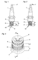
- the spark plug has an insulator body 1 and a spark plug housing 2 comprising the same.
- the ground electrode carrier housing 3 which in the in Fig. 1 shown commercial spark plug wearing the thread 9, with the spark plug z. B. is screwed into the cylinder head of an internal combustion engine.
- a hook electrode 4 is arranged as a ground electrode.
- the center electrode 5 protrudes from the insulator body 1 opposite the end of the hook electrode 4.
- the connection contact 7 is provided to connect the center electrode 5 guided in the insulator body 1 to an ignition plug (not shown).
- both ground electrode carrier housing sections 3 'and 3 carry a thread 9.
- the distance between the two sections 3' and 3" is selected here in such a way that at least two different ground electrode carrier housing sections 3 'and 3 "are provided.
- the ground electrode carrier housing section 3 “desirably has a higher thermal conductivity than the other ground electrode carrier housing section 3 ', whereby the heat occurring at the combustion chamber side end 10 can be quickly dissipated.
- the combustion chamber-side ground electrode carrier housing section 3 " is mounted as a ring on or welded to the other ground electrode carrier housing section 3.
- a favorable method for this purpose is that of the commercial spark plug according to FIG Fig. 1 First, the area 6 of the ground electrode carrier housing 3 together with ground electrode 4 is removed and then the other material having ground electrode support ring 3 "placed on the remaining in the commercial spark plug ground electrode housing portion 3 'and conveniently welded thereto Material as the spark plug housing 2. In a method otherwise analogous to the above-described method then not only a part of the ground electrode carrier housing 3, but the whole ground electrode carrier housing 3 of the standard spark plug is removed and replaced by a ground electrode carrier ring 3 "of other material. This is in turn welded to the spark plug housing 2. In both Variants is the pulsed or unpulsed laser welding a preferred welding method.
- a ground electrode carrier housing section 3 " which points toward a combustion chamber in the installed position of the spark plug, carries a ground electrode 8 or a ground electrode carrier arrangement or the ground electrode carrier housing 3 is arranged. This is exemplary in Fig. 3 shown.
- the integrated ground electrode 8 sits in the interior of the section 3 ", is conveniently made of the same material as the section 3" and can be made in one piece with this.
- the thread 9 or the wall of the ground electrode carrier housing 3 or its combustion chamber-side section 3 protrudes over the ignition point 12 (see FIG Fig. 4 ).
- the center electrode 5 and / or the ground electrode 8 can - as known per se - carry an electrode plate 11, preferably made of precious metal, as an electrode. It is particularly advantageous if the combustion-chamber-side ground electrode carrier housing section 3 "or the entire ground electrode carrier housing 3 comprises a nickel-based alloy or a nickel-chromium alloy, which in addition to nickel and chromium also at least one of the elements aluminum, titanium, niobium, cobalt, copper A particularly preferred nickel-based alloy is the material number: 2.4816 marketed under the trade name "Inco Alloy 600."
- the spark plug housing 2 and the possibly present section 3 'of the ground electrode carrier housing 3 can be made from the hitherto customary usually be made cheaper materials.
- Fig. 4 shows a section along the line AA through the combustion chamber-side end of the ground electrode carrier housing 3.
- the mixture accessibility is improved to the ignition by the Ground electrode 8 comprehensive wall of the section 3 "or of the ground electrode carrier housing 3 is inclined towards the ground electrode 8 at an angle ⁇ between 10 ° and 60 ° with respect to a parallel to the center electrode 5 of the spark plug, at least in certain regions 30 ° preferred.
- a further improvement of the mixture accessibility to the ignition point 12 is as in Fig. 5 exemplified by recesses 15 at the combustion chamber end of the section 3 "and the ground electrode carrier housing 3 reached.
- ground electrode carrier housing 3 can also have further sections with in turn other materials.
Landscapes
- Engineering & Computer Science (AREA)
- Manufacturing & Machinery (AREA)
- Spark Plugs (AREA)
Description
- Die vorliegende Erfindung betrifft eine Zündkerze, insbesondere zur Verwendung in Brennkraftmaschinen, mit einem Zündkerzengehäuse und einem Masseelektrodenträgergehäuse.
- Die beim Stand der Technik bekannten Zündkerzen weisen ein Masseelektrodenträgergehäuse auf, mit welchem die Zündkerze z. B. in den Zylinderkopf einer Brennkraftmaschine eingeführt wird. Meist weist das Masseelektrodenträgergehäuse an seiner Außenfläche ein Gewinde auf, mit dem die Zündkerze in den Zylinderkopf eingeschraubt werden kann. Es sind jedoch auch Zündkerzen mit glatten zylinderförmigen Masseelektrodenträgergehäusen bekannt, welche in den Zylinderkopf eingeklemmt oder z. B. mit einem Bajonett-Verschluss daran befestigt werden. An dem brennkammerseitigen Ende des Masseelektrodenträgergehäuses sind eine oder mehrere Masseelektroden vorgesehen. Das Masseelektrodenträgergehäuse selber ist einstückig mit dem restlichen Zündkerzengehäuse ausgeführt oder daran mittels Widerstandsschweißverfahren angeschweißt. Bei den beim Stand der Technik bekannten Zündkerzen treten am brennkammerseitigen Ende des Masseelektrodenträgergehäuses häufig Probleme mit den dort extrem hohen Temperaturen auf. Es kommt immer wieder zur Heißkorrosion im Bereich des Masseelektrodenträgergehäuses und damit zur negativen Beeinträchtigung bzw. zur Zerstörung der Zündkerze.
-
DE 3 726 714 A1 , offenbart eine Zündkerze, insbesondere zur Verwendung in Brennkraftmaschinen, mit einem Zündkerzengehäuse und einem Masseelektrodengehäuse das ein anderes Material als das Zündkerzengehäuse aufweist. - Aufgabe der Erfindung ist es daher, eine Zündkerze bereitzustellen, bei der eine Heißkorrosion des Masseelektrodenträgergehäuses unterbunden ist.
- Dies wird erfindungsgemäß erreicht, mit einer Zündkerze, gemäß Anspruch 1.
- Erfindungsgemäß ist in dem Bereich, in dem die größte Hitzeentwicklung am Masseelektrodenträgergehäuse auftritt, ein spezielles Material vorgesehen, durch das die Heißkorrosion wirksam verhindert ist. Der restliche Aufbau der Zündkerze kann dabei in der bisher bekannten Form und unter Verwendung der auch bisher üblichen Materialien und damit in der Regel kostengünstig ausgeführt sein. Hierbei gibt es sowohl die Möglichkeit einen Teil des Masseelektrodenträgergehäuses, als auch das ganze Masseelektrodenträgergehäuse aus einem anderen Material als das Zündkerzengehäuse bzw. des daran verbliebenen anderen Teiles des Masseelektrodenträgergehäuses auszuführen.
- Ein geeignetes Verfahren zur Herstellung einer erfindungsgemäßen Zündkerze sieht vor, dass das Masseelektrodenträgergehäuse mit mindestens zwei Masseelektrodenträgergehäuseabschnitten ausgebildet wird, wobei diese unterschiedliche Materialien aufweisen und/oder das Masseelektrodenträgergehäuse aus einem anderen Material als das Zündkerzengehäuse ausgebildet wird. Besonders kostengünstig kann eine erfindungsgemäße Zündkerze ausgehend von einer handelsüblichen Zündkerze hergestellt werden, wenn an einer handelsüblichen Zündkerze mit einem Masseelektrodenträgergehäuse an dessen in Einbaustellung zu einer Brennkammer weisenden Ende ein Teil des Masseelektrodenträgergehäuses oder das gesamte Masseelektrodenträgergehäuse und gegebenenfalls die dort vorhandene Masseelektrode oder Masseelektrodenanordnung entfernt wird und anschließend ein Masseelektrodenträgerring auf den verbliebenen Teil des Masseelektrodenträgergehäuses oder auf das Zündkerzengehäuse der handelsüblichen Zündkerze aufgesetzt bzw. daran angeschweißt wird, wobei der Masseelektrodenträgerring anderes Material als der verbliebene Teil des Masseelektrodenträgergehäuses oder das Zündkerzengehäuse der handelsüblichen Zündkerze aufweist.
- Weitere Einzelheiten und Merkmale der vorliegenden Erfindung ergeben sich aus der nachfolgenden Figurenbeschreibung. Dabei zeigt:
- Fig. 1
- eine Zündkerze gemäß dem Stand der Technik,
- Fig. 2
- eine erfindungsgemäße Ausführungsvariante einer Zündkerze,
- Fig.3
- eine perspektivische Ansicht auf das brennkammerseitige Ende der erfindungsgemäßen Zündkerze aus
Fig. 2 in einer ersten Ausführungsform, - Fig. 4
- einen Schnitt durch den oberen Teil des Masseelektrodenträgergehäuses gemäß
Fig.3 entlang der Schnittgeraden AA und - Fig. 5
- eine weitere Ausführungsvariante des brennkammerseitigen Endes einer erfindungsgemäßen Zündkerze in perspektivischer Ansicht.
- Beim Stand der Technik gemäß
Fig. 1 weist die Zündkerze einen Isolatorkörper 1 sowie ein diesen umfassendes Zündkerzengehäuse 2 auf. Mit dem Zündkerzengehäuse 2 meist einstückig oder per Widerstandsschweißen verbunden ist das Masseelektrodenträgergehäuse 3, welches bei der inFig. 1 gezeigten handelsüblichen Zündkerze das Gewinde 9 trägt, mit dem die Zündkerze z. B. in den Zylinderkopf einer Brennkraftmaschine eingeschraubt wird. Am brennkammerseitigen bzw. zur Brennkammer weisenden Ende 10 des Masseelektrodenträgergehäuses 3 ist eine Hakenelektrode 4 als Masseelektrode angeordnet. Dem Ende der Hakenelektrode 4 gegenüber ragt die Mittelelektrode 5 aus dem Isolatorkörper 1. Zur Verbindung der im Isolatorkörper 1 geführten Mittelelektrode 5 mit einem nicht dargestellten Zündstecker ist der Anschlusskontakt 7 vorgesehen. - Während beim Stand der Technik das Masseelektrodenträgergehäuse 3 zusammen mit dem Zündkerzengehäuse 2 aus ein und dem selben Material gefertigt ist, sieht eine erste Variante der vorliegenden Erfindung, wie in
Fig. 2 gezeigt, zumindest zwei verschiedene Masseelektrodenträgergehäuseabschnitte 3' und 3" vor, welche voneinander unterschiedliches Material aufweisen. Beide Masseelektrodenträgergehäuseabschnitte 3' und 3" tragen im gezeigten Beispiel ein Gewinde 9. Der Abstand zwischen den beiden Abschnitten 3' und 3" ist hierbei so gewählt, dass beide Abschnitte zusammen in ein Standardgewinde eingeschraubt werden können. Um Heißkorrosion zu verhindern, weist der zu einer Brennkammer weisende Masseelektrodenträgergehäuseabschnitt 3" günstigerweise eine höhere Wärmeleitfähigkeit als der andere Masseelektrodenträgergehäuseabschnitt 3' auf, wodurch die am brennkammerseitigen Ende 10 auftretende Wärme schnell abgeführt werden kann. Im gezeigten Ausführungsbeispiel ist der brennkammerseitige Masseelektrodenträgergehäuseabschnitt 3" als Ring auf den anderen Masseelektrodenträgergehäuseabschnitt 3' aufgesetzt bzw. daran angeschweißt. Ein günstiges Verfahren sieht hierzu vor, dass von der handelsüblichen Zündkerze gemäßFig. 1 zunächst der Bereich 6 des Masseelektrodenträgergehäuses 3 samt Masseelektrode 4 entfernt und anschließend der anderes Material aufweisende Masseelektrodenträgerring 3" auf den in der handelsüblichen Zündkerze verbleibenden Masseelektrodenträgergehäuseabschnitt 3' aufgesetzt und günstigerweise daran angeschweißt wird. In einer zweiten erfindungsgemäßen Variante besteht das gesamte Masseelektrodenträgergehäuse 3 aus einem anderen Material als das Zündkerzengehäuse 2. Bei einem zum oben geschilderten Verfahren ansonsten analogen Herstellungsverfahren wird dann nicht nur ein Teil des Masseelektrodenträgergehäuses 3, sondern das ganze Masseelektrodenträgergehäuse 3 der Standardzündkerze entfernt und durch einen Masseelektrodenträgerring 3" aus anderem Material ersetzt. Dieser wird wiederum am Zündkerzengehäuse 2 angeschweißt. In beiden Varianten ist das gepulste oder ungepulste Laserschweißverfahren ein bevorzugtes Schweißverfahren. - Der in Einbaustellung der Zündkerze zu einer Brennkammer weisende Masseelektrodenträgergehäuseabschnitt 3" trägt eine Masseelektrode 8 oder eine Masseelektrodenträgeranordnung. Eine besonders betriebsfeste Zündkerze wird hierbei erreicht, wenn die Masseelektrode 8 oder die Masseelektrodenanordnung im Wesentlichen im Inneren des in Einbaustellung der Zündkerze zu einer Brennkammer weisenden Masseelektrodenträgergehäuseabschnitts 3" bzw. des Masseelektrodenträgergehäuses 3 angeordnet ist. Dies ist beispielhaft in
Fig. 3 gezeigt. Die integrierte Masseelektrode 8 sitzt dabei im Inneren des Abschnitts 3", ist günstigerweise aus demselben Material wie der Abschnitt 3" gefertigt und kann einstückig mit diesem ausgeführt sein. Das Gewinde 9 bzw. die Wandung des Masseelektrodenträgergehäuses 3 bzw. seines brennkammerseitigen Abschnitts 3" ragt günstigerweise über den Zündort 12 (sieheFig. 4 ) hinaus. Vor allem durch ein einstückiges Ausbilden der Masseelektrode 8 mit dem Masseelektrodenträgergehäuse 3 oder seinem brennkammerseitigen Abschnitt 3" wird eine optimale Wärmeableitung von der unmittelbaren Zündstelle in die Aufnahme der Zündkerze (zum Beispiel das Gewinde eines Zylinderkopfes) erreicht. - Die Mittelelektrode 5 und/oder die Masseelektrode 8 kann - wie an sich bekannt - ein Elektrodenplättchen 11, vorzugsweise aus Edelmetall, als Elektrode tragen. Besonders vorteilhaft ist es, wenn der brennkammerseitige Masseelektrodenträgergehäuseabschnitt 3" bzw. das gesamte Masseelektrodenträgergehäuse 3 eine Nickelbasislegierung bzw. eine Nickel-Chrom-Legierung aufweist, wobei diese neben Nickel und Chrom zusätzlich auch mindestens eines der Elemente Aluminium, Titan, Niob, Kobalt, Kupfer, Molybdän, Wolfram oder Eisen aufweisen kann. Eine besonders bevorzugte Nickelbasislegierung ist der unter dem Handelsnamen "Inco Alloy 600" vertriebene Werkstoff - Nr.: 2.4816. Das Zündkerzengehäuse 2 sowie der gegebenenfalls vorhandene Abschnitt 3' des Masseelektrodenträgergehäuses 3 kann aus den bisher üblichen, meist kostengünstigeren Materialien gefertigt sein.
-
Fig. 4 zeigt einen Schnitt entlang der Geraden AA durch das brennkammerseitige Ende des Masseelektrodenträgergehäuses 3. Neben der bereits besprochenen einstückigen Ausbildung der Masseelektrode 8 mit dem Abschnitt 3" und dem Vorsehen von Elektrodenplättchen 11 (vorzugsweise aus Edelmetall) wird die Gemischzugänglichkeit zum Zündort verbessert, indem die die Masseelektrode 8 umfassende Wandung des Abschnitts 3" oder des Masseelektrodenträgergehäuses 3 zumindest bereichsweise zur Masseelektrode 8 hin, in einem Winkel α zwischen 10° und 60° gegen eine Parallele 13 zur Mittelelektrode 5 der Zündkerze, geneigt ist. Im Sinne einer besonders optimalen Gemischzugänglichkeit zum Zündort 12 sind Neigungswinkel α von ca. 30° bevorzugt. - Eine weitere Verbesserung der Gemischzugänglichkeit zum Zündort 12 wird wie in
Fig. 5 beispielhaft gezeigt durch Ausnehmungen 15 am brennkammerseitigen Ende des Abschnittes 3" bzw. des Masseelektrodenträgergehäuses 3 erreicht. - Des weiteren sind unterschiedlichste Masseelektrodenkonfigurationen möglich. Neben den gezeigten zwei Abschnitten 3'und 3" kann das Masseelektrodenträgergehäuse 3 auch weitere Abschnitte mit wiederum anderen Materialien aufweisen.
Claims (8)
- Zündkerze, insbesondere zur Verwendung in Brennkraftmaschinen, mit einem Zündkerzengehäuse und einem Masseelektrodenträgergehäuse, wobei das Masseelektrodenträgergehäuse (3) zumindest zwei jeweils ein Gewinde (9) und voneinander unterschiedliche Materiallen aufweisende Masseelektrodenträgergehäuseabschnitte (3', 3") hat, wobei die Zündkerze über die Gewinde (9) in einem Zylinderkopf befestigbar ist und/oder das Masseelektrodenträgergehäuse (3) anderes Material als das Zündkerzengehäuse und ein Gewinde (9) aufweist, wobei die Zündkerze über das Gewinde (9) in einem Zylinderkopf befestigbar ist.
- Zündkerze nach Anspruch 1, dadurch gekennzeichnet, dass der in Einbaustellung der Zündkerze zu einer Brennkammer weisende Masseelektrodenträgergehäuseabschnitt (3") eine höhere Wärmeleitfähigkeit als der andere oder die anderen Masseelektrodenträgergehäuseabschnitt(e) (3') und/oder das Masseelektrodenträgergehäuse (3) eine höhere Wärmeleitfähigkeit als das Zündkerzengehäuse (2) aufweist.
- Zündkerze nach einem der Ansprüche 1 oder 2, dadurch gekennzeichnet, dass der in Einbaustellung der Zündkerze zu einer Brennkammer weisende Masseelektrodenträgergehäuseabschnitt (3") oder das gesamte Masseelektrodenträgergehäuse (3) als Ring auf den anderen oder die anderen Masseelektrodenträgergehäuseabschnitt(e) (3') oder das Zündkerzengehäuse (2) aufgesetzt bzw. daran angeschweißt ist.
- Zündkerze nach einem der Ansprüche 1 bis 3, dadurch gekennzeichnet, dass der in Einbaustellung der Zündkerze zu einer Brennkammer weisende Masseelektrodenträgergehäuseabschnitt (3") bzw. das Masseelektrodenträgergehäuse (3) eine Masseelektrode (8) oder eine Masseelektrodenanordnung trägt und vorzugsweise einstückig mit der Masseelektrode (8) ausgebildet ist.
- Zündkerze nach Anspruch 4, dadurch gekennzeichnet, dass die Masseelektrode (8) oder die Masseelektrodenanordnung im Wesentlichen im Inneren des in Einbaustellung der Zündkerze zu einer Brennkammer weisenden Masseelektrodenträgergehäuseabschnitts (3") oder des Masseelektrodenträgergehäuses (3) angeordnet ist.
- Zündkerze nach Anspruch 5, dadurch gekennzeichnet, dass die die Masseelektrode (8) umfassende Wandung des in Einbaustellung der Zündkerze zu einer Brennkammer weisenden Masseelektrodenträgergehäuseabschnitts (3") oder des Masseeleklrodenträgergehäuses (3) zumindest bereichsweise zur Masseelektrode (8) hin, in einem Winkel α zwischen 10° und 60° gegen eine Parallele (13) zur Mittelelektrode (5) der Zündkerze, geneigt ist.
- Zündkerze nach einem der Ansprüche 1 bis 6, dadurch gekennzeichnet, dass der in Einbaustellung der Zündkerze zu einer Brennkammer weisende Masseelektrodenträgergehäuseabschnitt (3") eine Nickelbasislegierung bzw. eine Nickel-Chrom-Legierung aufweist.
- Zündkerze nach Anspruch 7, dadurch gekennzeichnet, dass die Nickel-Chrom-Legierung neben Nickel und Chrom zusätzlich zumindest eines der Elemente Aluminium, Titan, Niob, Kobalt, Kupfer, Molybdän, Wolfram oder Eisen aufweist.
Applications Claiming Priority (2)
| Application Number | Priority Date | Filing Date | Title |
|---|---|---|---|
| AT14852003 | 2003-09-19 | ||
| AT0148503A AT413904B (de) | 2003-09-19 | 2003-09-19 | Zündkerze |
Publications (3)
| Publication Number | Publication Date |
|---|---|
| EP1517416A2 EP1517416A2 (de) | 2005-03-23 |
| EP1517416A3 EP1517416A3 (de) | 2010-02-24 |
| EP1517416B1 true EP1517416B1 (de) | 2012-07-11 |
Family
ID=34140232
Family Applications (1)
| Application Number | Title | Priority Date | Filing Date |
|---|---|---|---|
| EP04019123A Revoked EP1517416B1 (de) | 2003-09-19 | 2004-08-12 | Zündkerze |
Country Status (4)
| Country | Link |
|---|---|
| US (1) | US7408293B2 (de) |
| EP (1) | EP1517416B1 (de) |
| JP (1) | JP2005093431A (de) |
| AT (1) | AT413904B (de) |
Families Citing this family (16)
| Publication number | Priority date | Publication date | Assignee | Title |
|---|---|---|---|---|
| US7823556B2 (en) * | 2006-06-19 | 2010-11-02 | Federal-Mogul World Wide, Inc. | Electrode for an ignition device |
| JP4970892B2 (ja) * | 2006-10-24 | 2012-07-11 | 株式会社デンソー | 内燃機関用のスパークプラグ |
| AT506140B1 (de) * | 2007-11-05 | 2009-11-15 | Francesconi Christian | Zündkerze |
| US20110050069A1 (en) * | 2009-08-25 | 2011-03-03 | Briggs & Stratton Corporation | Spark plug |
| AT509313B1 (de) | 2009-12-23 | 2011-12-15 | Ge Jenbacher Gmbh & Co Ohg | Zündkerze mit loch zum einstellen |
| US8584648B2 (en) | 2010-11-23 | 2013-11-19 | Woodward, Inc. | Controlled spark ignited flame kernel flow |
| US9476347B2 (en) | 2010-11-23 | 2016-10-25 | Woodward, Inc. | Controlled spark ignited flame kernel flow in fuel-fed prechambers |
| US9172217B2 (en) | 2010-11-23 | 2015-10-27 | Woodward, Inc. | Pre-chamber spark plug with tubular electrode and method of manufacturing same |
| JP5955668B2 (ja) * | 2012-07-03 | 2016-07-20 | 株式会社日本自動車部品総合研究所 | 点火プラグ |
| US9285120B2 (en) * | 2012-10-06 | 2016-03-15 | Coorstek, Inc. | Igniter shield device and methods associated therewith |
| US9856848B2 (en) | 2013-01-08 | 2018-01-02 | Woodward, Inc. | Quiescent chamber hot gas igniter |
| US9765682B2 (en) | 2013-06-10 | 2017-09-19 | Woodward, Inc. | Multi-chamber igniter |
| US9653886B2 (en) | 2015-03-20 | 2017-05-16 | Woodward, Inc. | Cap shielded ignition system |
| US9890689B2 (en) | 2015-10-29 | 2018-02-13 | Woodward, Inc. | Gaseous fuel combustion |
| EP3358686A1 (de) * | 2017-02-01 | 2018-08-08 | Kistler Holding AG | Zuendkerze und verfahren zu deren fertigung |
| JP7475317B2 (ja) * | 2021-07-09 | 2024-04-26 | 日本特殊陶業株式会社 | スパークプラグ |
Citations (1)
| Publication number | Priority date | Publication date | Assignee | Title |
|---|---|---|---|---|
| GB154123A (en) * | 1920-04-07 | 1920-11-25 | Albert Edward Watts | Improvements in spark plugs |
Family Cites Families (18)
| Publication number | Priority date | Publication date | Assignee | Title |
|---|---|---|---|---|
| FR1101263A (fr) * | 1954-03-18 | 1955-10-04 | Floquet | Bougie d'allumage |
| JPS4934201B1 (de) * | 1970-12-11 | 1974-09-12 | ||
| US3958144A (en) * | 1973-10-01 | 1976-05-18 | Franks Harry E | Spark plug |
| CA1010329A (en) * | 1973-10-01 | 1977-05-17 | Harry E. Franks | Spark plug |
| EP0020200A1 (de) * | 1979-06-04 | 1980-12-10 | The Bendix Corporation | Zündkerze |
| US4540910A (en) * | 1982-11-22 | 1985-09-10 | Nippondenso Co., Ltd. | Spark plug for internal-combustion engine |
| US4491101A (en) * | 1983-09-06 | 1985-01-01 | Strumbos William P | Multiple heat-range spark plug |
| DE3726714A1 (de) * | 1987-08-11 | 1989-02-23 | Helmut Koehler | Zuendkerze |
| JPH01302678A (ja) * | 1988-02-02 | 1989-12-06 | Ngk Spark Plug Co Ltd | スパークプラグ |
| DE68924526T2 (de) * | 1989-01-09 | 1996-04-04 | Ngk Spark Plug Co | Zündkerzenzusammenbau. |
| JP2566878B2 (ja) * | 1994-03-15 | 1996-12-25 | 日本特殊陶業株式会社 | 内燃機関用スパークプラグの製造方法 |
| US5493171A (en) * | 1994-10-05 | 1996-02-20 | Southwest Research Institute | Spark plug having titanium diboride electrodes |
| GB2327459A (en) * | 1997-07-17 | 1999-01-27 | Dawson Royalties Ltd | Spark plug for i.c. engines |
| JP2000068030A (ja) * | 1998-08-25 | 2000-03-03 | Ngk Spark Plug Co Ltd | 点火プラグ、シリンダヘッド及び内燃機関 |
| JP2000195646A (ja) * | 1998-12-25 | 2000-07-14 | Ngk Spark Plug Co Ltd | スパ―クプラグの製造方法及びスパ―クプラグ |
| JP4305713B2 (ja) * | 2000-12-04 | 2009-07-29 | 株式会社デンソー | スパークプラグ |
| AT410151B (de) * | 2001-06-05 | 2003-02-25 | Jenbacher Ag | Zündkerze einer brennkraftmaschine |
| AT410150B (de) * | 2001-06-05 | 2003-02-25 | Jenbacher Ag | Zündkerze einer brennkraftmaschine |
-
2003
- 2003-09-19 AT AT0148503A patent/AT413904B/de not_active IP Right Cessation
-
2004
- 2004-08-12 EP EP04019123A patent/EP1517416B1/de not_active Revoked
- 2004-09-10 JP JP2004263260A patent/JP2005093431A/ja active Pending
- 2004-09-20 US US10/945,821 patent/US7408293B2/en not_active Expired - Fee Related
Patent Citations (1)
| Publication number | Priority date | Publication date | Assignee | Title |
|---|---|---|---|---|
| GB154123A (en) * | 1920-04-07 | 1920-11-25 | Albert Edward Watts | Improvements in spark plugs |
Also Published As
| Publication number | Publication date |
|---|---|
| JP2005093431A (ja) | 2005-04-07 |
| AT413904B (de) | 2006-07-15 |
| US20050062386A1 (en) | 2005-03-24 |
| US7408293B2 (en) | 2008-08-05 |
| EP1517416A2 (de) | 2005-03-23 |
| ATA14852003A (de) | 2005-10-15 |
| EP1517416A3 (de) | 2010-02-24 |
Similar Documents
| Publication | Publication Date | Title |
|---|---|---|
| EP1517416B1 (de) | Zündkerze | |
| AT410151B (de) | Zündkerze einer brennkraftmaschine | |
| DE69304812T2 (de) | Zündkerze | |
| DE10201697B4 (de) | Zündkerzenaufbau mit hohem Wärmewiderstand und hoher Haltbarkeit | |
| DE102007000148B4 (de) | Zündkerze für eine Brennkraftmaschine | |
| DE60222485T2 (de) | Zündkerze | |
| EP3694684B1 (de) | Zündkerze und verfahren zur herstellung einer zündkerze | |
| EP0505368B1 (de) | Verfahren zur herstellung von elektroden für zündkerzen sowie zündkerzen-elektroden | |
| DE112009000215T5 (de) | Masseabschirmung mit hohem Gewinde | |
| DE2446929A1 (de) | Zuendkerze | |
| DE102004044152A1 (de) | Zündkerze | |
| DE69306499T2 (de) | Herstellungsverfahren für Zündkerze | |
| DE69601608T2 (de) | Zündkerze für Verbrennungsmotor | |
| DE69225686T2 (de) | Zündkerzenelektrode und Herstellungsverfahren | |
| DE102013108613B4 (de) | Zündkerze mit Verfahren zum Anbringen eines Zündplättchens an einer Elektrode | |
| DE3821688A1 (de) | Zuendelektroden in einer vorkammerzuendkerze | |
| DE10205588B4 (de) | Zündkerze mit einem höheren Verschleißwiderstand an der Mittelelektrode, und Verfahren zum Herstellen derselben | |
| DE102004060866A1 (de) | Zündkerze mit verbesserter Verbindungsfestigkeit zwischen Edelmetallelement und Masseelektrode | |
| EP1338065B1 (de) | Zündkerze für eine brennkraftmaschine und verfahren zur herstellung einer mittelektrode für eine zündkerze einer brennkraftmaschine | |
| DE102015118935B4 (de) | Verfahren zum Herstellen einer Zündkerze | |
| DE3519101A1 (de) | Fraesmeissel fuer eine fraesvorrichtung | |
| DE112013001321B4 (de) | Masseelektrode, Zündkerze und Verfahren zur Bildung einer Masseelektrode | |
| DE102019101690B4 (de) | Zündkerze | |
| EP1269590A1 (de) | Zündkerze für eine brennkraftmaschine | |
| DE112022003088T5 (de) | Zündkerze |
Legal Events
| Date | Code | Title | Description |
|---|---|---|---|
| PUAI | Public reference made under article 153(3) epc to a published international application that has entered the european phase |
Free format text: ORIGINAL CODE: 0009012 |
|
| AK | Designated contracting states |
Kind code of ref document: A2 Designated state(s): AT BE BG CH CY CZ DE DK EE ES FI FR GB GR HU IE IT LI LU MC NL PL PT RO SE SI SK TR |
|
| AX | Request for extension of the european patent |
Extension state: AL HR LT LV MK |
|
| PUAL | Search report despatched |
Free format text: ORIGINAL CODE: 0009013 |
|
| AK | Designated contracting states |
Kind code of ref document: A3 Designated state(s): AT BE BG CH CY CZ DE DK EE ES FI FR GB GR HU IE IT LI LU MC NL PL PT RO SE SI SK TR |
|
| AX | Request for extension of the european patent |
Extension state: AL HR LT LV MK |
|
| 17P | Request for examination filed |
Effective date: 20100628 |
|
| AKX | Designation fees paid |
Designated state(s): AT BE BG CH CY CZ DE DK EE ES FI FR GB GR HU IE IT LI LU MC NL PL PT RO SE SI SK TR |
|
| 17Q | First examination report despatched |
Effective date: 20110119 |
|
| GRAP | Despatch of communication of intention to grant a patent |
Free format text: ORIGINAL CODE: EPIDOSNIGR1 |
|
| GRAS | Grant fee paid |
Free format text: ORIGINAL CODE: EPIDOSNIGR3 |
|
| GRAA | (expected) grant |
Free format text: ORIGINAL CODE: 0009210 |
|
| AK | Designated contracting states |
Kind code of ref document: B1 Designated state(s): AT BE BG CH CY CZ DE DK EE ES FI FR GB GR HU IE IT LI LU MC NL PL PT RO SE SI SK TR |
|
| REG | Reference to a national code |
Ref country code: GB Ref legal event code: FG4D Free format text: NOT ENGLISH |
|
| REG | Reference to a national code |
Ref country code: CH Ref legal event code: EP |
|
| REG | Reference to a national code |
Ref country code: AT Ref legal event code: REF Ref document number: 566539 Country of ref document: AT Kind code of ref document: T Effective date: 20120715 |
|
| REG | Reference to a national code |
Ref country code: IE Ref legal event code: FG4D Free format text: LANGUAGE OF EP DOCUMENT: GERMAN |
|
| REG | Reference to a national code |
Ref country code: DE Ref legal event code: R096 Ref document number: 502004013619 Country of ref document: DE Effective date: 20120906 |
|
| REG | Reference to a national code |
Ref country code: NL Ref legal event code: T3 |
|
| PG25 | Lapsed in a contracting state [announced via postgrant information from national office to epo] |
Ref country code: CY Free format text: LAPSE BECAUSE OF FAILURE TO SUBMIT A TRANSLATION OF THE DESCRIPTION OR TO PAY THE FEE WITHIN THE PRESCRIBED TIME-LIMIT Effective date: 20120711 Ref country code: FI Free format text: LAPSE BECAUSE OF FAILURE TO SUBMIT A TRANSLATION OF THE DESCRIPTION OR TO PAY THE FEE WITHIN THE PRESCRIBED TIME-LIMIT Effective date: 20120711 |
|
| BERE | Be: lapsed |
Owner name: GE JENBACHER GMBH & CO OHG Effective date: 20120831 |
|
| PG25 | Lapsed in a contracting state [announced via postgrant information from national office to epo] |
Ref country code: PL Free format text: LAPSE BECAUSE OF FAILURE TO SUBMIT A TRANSLATION OF THE DESCRIPTION OR TO PAY THE FEE WITHIN THE PRESCRIBED TIME-LIMIT Effective date: 20120711 Ref country code: SI Free format text: LAPSE BECAUSE OF FAILURE TO SUBMIT A TRANSLATION OF THE DESCRIPTION OR TO PAY THE FEE WITHIN THE PRESCRIBED TIME-LIMIT Effective date: 20120711 Ref country code: GR Free format text: LAPSE BECAUSE OF FAILURE TO SUBMIT A TRANSLATION OF THE DESCRIPTION OR TO PAY THE FEE WITHIN THE PRESCRIBED TIME-LIMIT Effective date: 20121012 Ref country code: SE Free format text: LAPSE BECAUSE OF FAILURE TO SUBMIT A TRANSLATION OF THE DESCRIPTION OR TO PAY THE FEE WITHIN THE PRESCRIBED TIME-LIMIT Effective date: 20120711 Ref country code: PT Free format text: LAPSE BECAUSE OF FAILURE TO SUBMIT A TRANSLATION OF THE DESCRIPTION OR TO PAY THE FEE WITHIN THE PRESCRIBED TIME-LIMIT Effective date: 20121112 |
|
| REG | Reference to a national code |
Ref country code: CH Ref legal event code: PL |
|
| PG25 | Lapsed in a contracting state [announced via postgrant information from national office to epo] |
Ref country code: MC Free format text: LAPSE BECAUSE OF NON-PAYMENT OF DUE FEES Effective date: 20120831 |
|
| PLBI | Opposition filed |
Free format text: ORIGINAL CODE: 0009260 |
|
| PG25 | Lapsed in a contracting state [announced via postgrant information from national office to epo] |
Ref country code: LI Free format text: LAPSE BECAUSE OF NON-PAYMENT OF DUE FEES Effective date: 20120831 Ref country code: RO Free format text: LAPSE BECAUSE OF FAILURE TO SUBMIT A TRANSLATION OF THE DESCRIPTION OR TO PAY THE FEE WITHIN THE PRESCRIBED TIME-LIMIT Effective date: 20120711 Ref country code: EE Free format text: LAPSE BECAUSE OF FAILURE TO SUBMIT A TRANSLATION OF THE DESCRIPTION OR TO PAY THE FEE WITHIN THE PRESCRIBED TIME-LIMIT Effective date: 20120711 Ref country code: ES Free format text: LAPSE BECAUSE OF FAILURE TO SUBMIT A TRANSLATION OF THE DESCRIPTION OR TO PAY THE FEE WITHIN THE PRESCRIBED TIME-LIMIT Effective date: 20121022 Ref country code: CZ Free format text: LAPSE BECAUSE OF FAILURE TO SUBMIT A TRANSLATION OF THE DESCRIPTION OR TO PAY THE FEE WITHIN THE PRESCRIBED TIME-LIMIT Effective date: 20120711 Ref country code: DK Free format text: LAPSE BECAUSE OF FAILURE TO SUBMIT A TRANSLATION OF THE DESCRIPTION OR TO PAY THE FEE WITHIN THE PRESCRIBED TIME-LIMIT Effective date: 20120711 Ref country code: CH Free format text: LAPSE BECAUSE OF NON-PAYMENT OF DUE FEES Effective date: 20120831 |
|
| 26 | Opposition filed |
Opponent name: REININGER, JAN Effective date: 20130408 |
|
| REG | Reference to a national code |
Ref country code: FR Ref legal event code: ST Effective date: 20130430 |
|
| PLAX | Notice of opposition and request to file observation + time limit sent |
Free format text: ORIGINAL CODE: EPIDOSNOBS2 |
|
| REG | Reference to a national code |
Ref country code: IE Ref legal event code: MM4A |
|
| PG25 | Lapsed in a contracting state [announced via postgrant information from national office to epo] |
Ref country code: SK Free format text: LAPSE BECAUSE OF FAILURE TO SUBMIT A TRANSLATION OF THE DESCRIPTION OR TO PAY THE FEE WITHIN THE PRESCRIBED TIME-LIMIT Effective date: 20120711 Ref country code: BE Free format text: LAPSE BECAUSE OF NON-PAYMENT OF DUE FEES Effective date: 20120831 |
|
| GBPC | Gb: european patent ceased through non-payment of renewal fee |
Effective date: 20121011 |
|
| REG | Reference to a national code |
Ref country code: DE Ref legal event code: R026 Ref document number: 502004013619 Country of ref document: DE Effective date: 20130408 |
|
| PG25 | Lapsed in a contracting state [announced via postgrant information from national office to epo] |
Ref country code: BG Free format text: LAPSE BECAUSE OF FAILURE TO SUBMIT A TRANSLATION OF THE DESCRIPTION OR TO PAY THE FEE WITHIN THE PRESCRIBED TIME-LIMIT Effective date: 20121011 Ref country code: IE Free format text: LAPSE BECAUSE OF NON-PAYMENT OF DUE FEES Effective date: 20120812 Ref country code: GB Free format text: LAPSE BECAUSE OF NON-PAYMENT OF DUE FEES Effective date: 20121011 |
|
| PG25 | Lapsed in a contracting state [announced via postgrant information from national office to epo] |
Ref country code: FR Free format text: LAPSE BECAUSE OF NON-PAYMENT OF DUE FEES Effective date: 20120911 |
|
| PLAF | Information modified related to communication of a notice of opposition and request to file observations + time limit |
Free format text: ORIGINAL CODE: EPIDOSCOBS2 |
|
| PG25 | Lapsed in a contracting state [announced via postgrant information from national office to epo] |
Ref country code: TR Free format text: LAPSE BECAUSE OF FAILURE TO SUBMIT A TRANSLATION OF THE DESCRIPTION OR TO PAY THE FEE WITHIN THE PRESCRIBED TIME-LIMIT Effective date: 20120711 |
|
| PG25 | Lapsed in a contracting state [announced via postgrant information from national office to epo] |
Ref country code: LU Free format text: LAPSE BECAUSE OF NON-PAYMENT OF DUE FEES Effective date: 20120812 |
|
| PG25 | Lapsed in a contracting state [announced via postgrant information from national office to epo] |
Ref country code: HU Free format text: LAPSE BECAUSE OF FAILURE TO SUBMIT A TRANSLATION OF THE DESCRIPTION OR TO PAY THE FEE WITHIN THE PRESCRIBED TIME-LIMIT Effective date: 20040812 |
|
| RDAF | Communication despatched that patent is revoked |
Free format text: ORIGINAL CODE: EPIDOSNREV1 |
|
| REG | Reference to a national code |
Ref country code: DE Ref legal event code: R064 Ref document number: 502004013619 Country of ref document: DE Ref country code: DE Ref legal event code: R103 Ref document number: 502004013619 Country of ref document: DE |
|
| PGFP | Annual fee paid to national office [announced via postgrant information from national office to epo] |
Ref country code: NL Payment date: 20140826 Year of fee payment: 11 Ref country code: DE Payment date: 20140827 Year of fee payment: 11 |
|
| RDAG | Patent revoked |
Free format text: ORIGINAL CODE: 0009271 |
|
| STAA | Information on the status of an ep patent application or granted ep patent |
Free format text: STATUS: PATENT REVOKED |
|
| PGFP | Annual fee paid to national office [announced via postgrant information from national office to epo] |
Ref country code: AT Payment date: 20140721 Year of fee payment: 11 |
|
| 27W | Patent revoked |
Effective date: 20140814 |
|
| REG | Reference to a national code |
Ref country code: DE Ref legal event code: R107 Ref document number: 502004013619 Country of ref document: DE Effective date: 20150212 |
|
| REG | Reference to a national code |
Ref country code: AT Ref legal event code: MA03 Ref document number: 566539 Country of ref document: AT Kind code of ref document: T Effective date: 20140814 |
|
| PGFP | Annual fee paid to national office [announced via postgrant information from national office to epo] |
Ref country code: IT Payment date: 20150825 Year of fee payment: 12 |