EP1516990B1 - Zusammengesetztes Bauteil, insbesondere für ein Schiebefenster eines Kraftfahrzeugs - Google Patents
Zusammengesetztes Bauteil, insbesondere für ein Schiebefenster eines Kraftfahrzeugs Download PDFInfo
- Publication number
- EP1516990B1 EP1516990B1 EP04021818A EP04021818A EP1516990B1 EP 1516990 B1 EP1516990 B1 EP 1516990B1 EP 04021818 A EP04021818 A EP 04021818A EP 04021818 A EP04021818 A EP 04021818A EP 1516990 B1 EP1516990 B1 EP 1516990B1
- Authority
- EP
- European Patent Office
- Prior art keywords
- guide rail
- upper shell
- lower shell
- rail according
- shell
- Prior art date
- Legal status (The legal status is an assumption and is not a legal conclusion. Google has not performed a legal analysis and makes no representation as to the accuracy of the status listed.)
- Expired - Lifetime
Links
- 238000004140 cleaning Methods 0.000 claims description 5
- 238000003466 welding Methods 0.000 claims description 4
- 230000002093 peripheral effect Effects 0.000 claims description 3
- 238000004026 adhesive bonding Methods 0.000 claims description 2
- 230000003014 reinforcing effect Effects 0.000 abstract description 2
- 229910000831 Steel Inorganic materials 0.000 description 3
- 239000002131 composite material Substances 0.000 description 3
- 238000011161 development Methods 0.000 description 3
- 230000018109 developmental process Effects 0.000 description 3
- 239000010959 steel Substances 0.000 description 3
- 239000002184 metal Substances 0.000 description 2
- 238000005452 bending Methods 0.000 description 1
- 239000013013 elastic material Substances 0.000 description 1
- 238000001746 injection moulding Methods 0.000 description 1
- 238000009434 installation Methods 0.000 description 1
- 238000004519 manufacturing process Methods 0.000 description 1
- 230000035515 penetration Effects 0.000 description 1
Images



Classifications
-
- E—FIXED CONSTRUCTIONS
- E05—LOCKS; KEYS; WINDOW OR DOOR FITTINGS; SAFES
- E05D—HINGES OR SUSPENSION DEVICES FOR DOORS, WINDOWS OR WINGS
- E05D15/00—Suspension arrangements for wings
- E05D15/06—Suspension arrangements for wings for wings sliding horizontally more or less in their own plane
- E05D15/10—Suspension arrangements for wings for wings sliding horizontally more or less in their own plane movable out of one plane into a second parallel plane
- E05D15/1042—Suspension arrangements for wings for wings sliding horizontally more or less in their own plane movable out of one plane into a second parallel plane with transversely moving carriage
- E05D15/1047—Suspension arrangements for wings for wings sliding horizontally more or less in their own plane movable out of one plane into a second parallel plane with transversely moving carriage specially adapted for vehicles
-
- B—PERFORMING OPERATIONS; TRANSPORTING
- B60—VEHICLES IN GENERAL
- B60J—WINDOWS, WINDSCREENS, NON-FIXED ROOFS, DOORS, OR SIMILAR DEVICES FOR VEHICLES; REMOVABLE EXTERNAL PROTECTIVE COVERINGS SPECIALLY ADAPTED FOR VEHICLES
- B60J1/00—Windows; Windscreens; Accessories therefor
- B60J1/08—Windows; Windscreens; Accessories therefor arranged at vehicle sides
- B60J1/12—Windows; Windscreens; Accessories therefor arranged at vehicle sides adjustable
- B60J1/16—Windows; Windscreens; Accessories therefor arranged at vehicle sides adjustable slidable
-
- E—FIXED CONSTRUCTIONS
- E05—LOCKS; KEYS; WINDOW OR DOOR FITTINGS; SAFES
- E05D—HINGES OR SUSPENSION DEVICES FOR DOORS, WINDOWS OR WINGS
- E05D15/00—Suspension arrangements for wings
- E05D15/06—Suspension arrangements for wings for wings sliding horizontally more or less in their own plane
- E05D15/0621—Details, e.g. suspension or supporting guides
- E05D15/066—Details, e.g. suspension or supporting guides for wings supported at the bottom
- E05D15/0686—Tracks
-
- E—FIXED CONSTRUCTIONS
- E05—LOCKS; KEYS; WINDOW OR DOOR FITTINGS; SAFES
- E05D—HINGES OR SUSPENSION DEVICES FOR DOORS, WINDOWS OR WINGS
- E05D15/00—Suspension arrangements for wings
- E05D15/06—Suspension arrangements for wings for wings sliding horizontally more or less in their own plane
- E05D15/10—Suspension arrangements for wings for wings sliding horizontally more or less in their own plane movable out of one plane into a second parallel plane
- E05D15/1042—Suspension arrangements for wings for wings sliding horizontally more or less in their own plane movable out of one plane into a second parallel plane with transversely moving carriage
- E05D2015/1055—Suspension arrangements for wings for wings sliding horizontally more or less in their own plane movable out of one plane into a second parallel plane with transversely moving carriage with slanted or curved track sections or cams
-
- E—FIXED CONSTRUCTIONS
- E05—LOCKS; KEYS; WINDOW OR DOOR FITTINGS; SAFES
- E05D—HINGES OR SUSPENSION DEVICES FOR DOORS, WINDOWS OR WINGS
- E05D15/00—Suspension arrangements for wings
- E05D15/06—Suspension arrangements for wings for wings sliding horizontally more or less in their own plane
- E05D15/10—Suspension arrangements for wings for wings sliding horizontally more or less in their own plane movable out of one plane into a second parallel plane
- E05D15/1042—Suspension arrangements for wings for wings sliding horizontally more or less in their own plane movable out of one plane into a second parallel plane with transversely moving carriage
- E05D2015/106—Suspension arrangements for wings for wings sliding horizontally more or less in their own plane movable out of one plane into a second parallel plane with transversely moving carriage transversely orientated track sections
-
- E—FIXED CONSTRUCTIONS
- E05—LOCKS; KEYS; WINDOW OR DOOR FITTINGS; SAFES
- E05Y—INDEXING SCHEME ASSOCIATED WITH SUBCLASSES E05D AND E05F, RELATING TO CONSTRUCTION ELEMENTS, ELECTRIC CONTROL, POWER SUPPLY, POWER SIGNAL OR TRANSMISSION, USER INTERFACES, MOUNTING OR COUPLING, DETAILS, ACCESSORIES, AUXILIARY OPERATIONS NOT OTHERWISE PROVIDED FOR, APPLICATION THEREOF
- E05Y2900/00—Application of doors, windows, wings or fittings thereof
- E05Y2900/50—Application of doors, windows, wings or fittings thereof for vehicles
- E05Y2900/53—Type of wing
- E05Y2900/55—Windows
Definitions
- the invention relates to a guide rail for a movable window, in particular a sliding window, of a motor vehicle, with a lower shell, an upper shell and an insert between the lower shell and the upper shell.
- the guide rail can also be used for other components of a motor vehicle, in particular for a movable plate or another body element of a motor vehicle.
- a composite component which consists of three individual parts, namely an upper part made of plastic by an injection molding process, a lower part made of plastic and a reinforcing part designed as a sheet metal part, which is arranged between the upper part and the lower part ,
- profile elements made of elastic material are effective in the region of the joints between the items.
- the object of the invention is to propose an improved guide rail of the type specified.
- a guide rail with the features of claim 1.
- the lower shell and the upper shell are connected to each other at joints.
- the upper shell and / or the lower shell have one or more guideways, in particular guide grooves, for a movable window or sliding window of a motor vehicle.
- the lower shell and the upper shell can be glued together and / or welded. As a result, an increased stability of the assembled component is achieved.
- the arrangement is preferably made such that the insert is frictionally and / or positively held between the lower shell and the upper shell, whereby the stability of the guide rail can be further increased. It is advantageous if the upper shell and the lower shell are connected to one another by vibration welding and / or friction welding.
- the lower shell and / or the upper shell may have ribs. These may be longitudinal ribs and / or diagonally or obliquely running ribs and / or transverse ribs.
- the joints lie on the peripheral edges of the lower shell and the upper shell and / or on the ribs.
- the joints may be in the region of the middle of the ribs and / or at the ends of the ribs.
- the ribs may have elevations at the ends of which the joints are provided.
- the insert has perforations.
- the openings are preferably formed as slots. It is advantageous if the perforations or slots extend in the longitudinal direction of the guide rail. As a result, residual stresses that can arise due to temperature fluctuations can be reduced. In the case of temperature fluctuations, the length changes of the upper shell and the lower shell are largest in the longitudinal direction. By also extending in the longitudinal direction openings or slots, the length expansions of the upper shell and the lower shell of the bonding of the insert are decoupled with the window. The upper shell and lower shell can extend in the longitudinal direction, without thereby exerting forces on the bonding of the insert with the window.
- a further advantageous embodiment is characterized in that the openings or slots of joints or elevations, which are joints, are penetrated.
- the surveys may in particular be surveys of the ribs or surveys provided on ribs.
- a further advantageous development is characterized in that alignment surfaces are provided on one or more perforations or slots and / or on one or more joints or elevations. In this way, a unique position assignment between the individual parts of the fauxge guide rail can be achieved, in particular between the depositor and the lower shell and / or the upper shell.
- compensating joints are provided at one or more perforations or slots and / or at one or more joints or elevations.
- a length compensation for different thermal expansions of the individual parts of the guide rail can be created.
- two alignment surfaces are provided between two adjacent perforations or slots and at the associated joints or elevations and if compensation gaps are provided at the other perforations or slots and joints or elevations.
- the insert has a bend. If the insert is designed as a sheet metal part, the bend can be made as a fold.
- the bend preferably serves as a joint, in particular splice, for a window or sliding window of a motor vehicle or a catcher, with the window or sliding window of the motor vehicle is connected or connectable.
- one or more catchers are provided which can be connected or connected to the assembled component.
- the catch or the catch are detachably connectable to the component.
- the catcher or the catcher can be inserted or clipped into the guide rail.
- the catcher is preferably connected to the body of a motor vehicle or connected, in particular glued or glued. It can form a joint with the window or sliding window.
- a part of a body 1 of a motor vehicle is shown, in which a window 2 is inserted, in which a movable window 3 is located.
- the fixed window 2 has in its upper and in its lower region in each case a guide rail 4, the catcher 5 are glued to the fixed window 2.
- the guide rail 4 shown in Fig. 1 is horizontal. In other applications, the guide rail 4 can run obliquely.
- the guide rail 4 As shown in Fig. 2, the guide rail 4, a lower shell 6 made of plastic, an upper shell 7 made of plastic and a depositor 8 made of steel or steel sheet, which lies in the assembled state between the lower shell 6 and the upper shell 7.
- the lower shell 6 has on its side facing the upper shell 7 in the manner shown in FIG. 2 way ribs, namely longitudinal ribs 9, 9 'and oblique ribs 10 which extend in a zigzag shape.
- the longitudinal rib 9 has six elevations 11, each pass through an associated longitudinal slot 12 of the insert 8.
- two further elevations 13 are provided which pass through corresponding further longitudinal slots 14 in the insert 8.
- the upper ends or end regions of the elevations 11 and further elevations 13 form joints 15 at which the lower shell 6 and the upper shell 7 are connected to one another, namely vibration-welded.
- Other joints 15 ' are formed by the peripheral edges of the lower shell 6 and the upper shell 7. Also at these joints 15 ', the lower shell 6 and the upper shell 7 are connected to each other, namely vibration welded.
- the insert 8 has an angled portion 16, which is connected to the flat main surface 17 of the insert 8 via a bend 18.
- Main surface 17, bend 18 and bend 16 are made by bending a steel sheet.
- the planar main surface 17 extends in the region of the middle between the lower shell 6 and the upper shell 7.
- the bend 18 is provided on the stationary window 2 facing side of the guide rail 4. It runs to the upper shell 7.
- the bend 16 runs from there to the lower shell 6. It is glued to the fixed window 2.
- each guide groove 19, 20 is provided, in which corresponding guide pins (not shown in the drawing) of the movable window 3 engage, which are guided in this way slidably.
- At one end of each guide groove 19, 20 each have a cleaning hole 21, 22 is present, so that the guide grooves 19, 20 are self-cleaning and a permanent function is ensured.
- two alignment surfaces 23, 24 are provided on the rib 9.
- the alignment surface 23 is formed by the right end surface of the elevation 11.
- the alignment surface 24 is formed by the left end surface of the elevation 11 'adjacent to the elevation 11 to the right.
- the associated alignment surfaces in the insert 8 are the right end surface of the longitudinal slot 12 and the left end surface of the longitudinal slot 12 ', which is adjacent to the longitudinal slot 12 on the right side.
- the area 25 of the insert 8 between the longitudinal slots 12 and 12 ' is in the manner shown in Fig. 6 way between the alignment surfaces 23 and 24 in the lower shell 6.
- the distance of the alignment surfaces 23 and 24 from each other is the same size as the length of the area 25, so that the area 25 is clearance between the alignment surfaces 23 and 24.
- the next to the right side region 26 of the insert 8 between the longitudinal slots 12 'and 12 is slightly shorter than the distance of the right end surface 27 of the elevation 11' and the left end surface 28 of the elevation 11". In this way, between the ends of the region 26 and the adjacent end surfaces 27th and 28 compensating joints 29 and 30 created by the different thermal expansion of the individual parts, ie the lower shell 6, the upper shell 7 and the insert 8, can be compensated.
- the elevations 11, 11 ', 11 are corresponding elevations 31, 31' and 31" of the upper shell 7, which may be formed on ribs of the upper shell 7, opposite.
- the joints 15 are located in the overlapping region of the elevations 11, 11 ', 11 "and 31, 31', 31".
- Recesses 32 are provided between the elevations 31, 31 'and 31 "of the upper shell 7.
- the guide rail 4 is connected to the fixed window 2, namely glued.
- a hedge is effected by two catcher 5, which are connected to the body 1 by a bond 40 and which have a contact surface 33 and a clip portion 34.
- the clip member 34 comprises an upwardly facing tab 35, from which a hook 36 is folded, and a clamping member 37, which points in the same direction as the hook 36 and which is bent out of the central region of the tab 35.
- the clip member 34 is clamped between the bend 16 of the insert 8 and the rear end wall 37 of the lower shell 6, as shown in Fig. 4.
- the rear end wall 37 has a shoulder 38 which is engaged behind by the end of the hook 36.
- the clip part 34 is connected to the contact surface 33 of the catcher 5 by a bend 39.
- the contact surface 33 abuts against the fixed window 2. It is glued in its lower end to the fixed window 2, through the same bonding 40, by means of which the fixed window 2 is glued to the body 1. By gluing 40, the contact surface 33 of the clip part 34 of the catcher 5 is further glued to the body 1.
- the lower shell 6 and the upper shell 7 are connected in their outer end regions by a further joint 41, in particular welded.
- the rear end wall 37 of the lower shell 6 has a groove 42 for each catcher 5, the depth of which substantially corresponds to the thickness of the flap 35.
- the described embodiment allows a cost-effective production by simple tools. By bonding a low-tension attachment is possible. This is a high stability achievable. Furthermore, a high design freedom is possible because additional panels are superfluous, so that a large design area is available.
Landscapes
- Engineering & Computer Science (AREA)
- Mechanical Engineering (AREA)
- Window Of Vehicle (AREA)
- Glass Compositions (AREA)
Description
- Die Erfindung betrifft eine Führungsschiene für ein bewegliches Fenster, insbesondere ein Schiebefenster, eines Kraftfahrzeugs, mit einer Unterschale, einer Oberschale und einem Einleger zwischen der Unterschale und der Oberschale. Die Führungsschiene kann auch für andere Bestandteile eines Kraftfahrzeugs verwendet werden, insbesondere für eine bewegliche Platte oder ein sonstiges Karosserieelement eines Kraftfahrzeugs.
- Aus der DE 199 16 619 A1 ist ein zusammengesetztes Bauteil bekannt, das aus drei Einzelteilen besteht, nämlich einem nach einem Spritzgußverfahren für Kunststoffe hergestelltem Oberteil, einem aus Kunststoff bestehenden Unterteil und einem als Blechteil ausgeführten Verstärkungsteil, das zwischen dem Oberteil und dem Unterteil angeordnet ist. Um Wärmedehnungen und Bauteiltoleranzen ausgleichen zu können, sind im Bereich der Verbindungsstellen zwischen den Einzelteilen Profilelemente aus elastischem Material wirksam.
- Aus der FR-A-2 577 483 ist ein zusammengesetztes Bauteil für ein Fenster eines Kraftfahrzeugs mit einer Unterschale und einer Oberschale bekannt, die zwischen sich ein Teil der Karosserie aufnehmen.
- Aufgabe der Erfindung ist es, eine verbesserte Führungsschiene der eingangs angegebenen Art vorzuschlagen.
- Erfindungsgemäß wird diese Aufgabe durch eine Führungsschiene mit den Merkmalen des Anspruchs 1 gelöst. Die Unterschale und die Oberschale sind an Fügestellen miteinander verbunden. Die Oberschale und/oder die Unterschale weisen eine oder mehrere Führungsbahnen, insbesondere Führungsnuten, für ein bewegliches Fenster oder Schiebefenster eines Kraftfahrzeugs auf.
- Vorteilhafte Weiterbildungen sind in den Unteransprüchen beschrieben.
- Die Unterschale und die Oberschale können miteinander verklebt und/oder verschweißt sein. Hierdurch wird eine erhöhte Stabilität des zusammengesetzten Bauteils erreicht. Die Anordnung ist vorzugsweise derart getroffen, daß der Einleger kraftschlüssig und/oder formschlüssig zwischen der Unterschale und der Oberschale gehalten ist, wodurch die Stabilität der Führungsschiene weiter erhöht werden kann. Vorteilhaft ist es, wenn die Oberschale und die Unterschale durch Vibrationsschweißen und/oder Reibschweißen miteinander verbunden sind.
- Die Unterschale und/oder die Oberschale können Rippen aufweisen. Dabei kann es sich um Längsrippen und/oder diagonal oder schräg verlaufende Rippen und/oder Querrippen handeln.
- Vorteilhaft ist es, wenn die Fügestellen an den umlaufenden Rändern der Unterschale und der Oberschale und/oder an den Rippen liegen. Die Fügestellen können im Bereich der Mitte der Rippen und/oder an den Enden der Rippen liegen. Insbesondere können die Rippen Erhebungen aufweisen, an deren Enden die Fügestellen vorgesehen sind.
- Eine weitere vorteilhafte Weiterbildung ist dadurch gekennzeichnet, daß der Einleger Durchbrechungen aufweist. Die Durchbrechungen sind vorzugsweise als Schlitze ausgebildet. Vorteilhaft ist es, wenn die, Durchbrechungen bzw. Schlitze in Längsrichtung der Führungsschiene verlaufen. Hierdurch können Eigenspannungen, die durch Temperaturschwankungen entstehen können, reduziert werden. Bei Temperaturschwankungen sind die Längenänderungen der Oberschale und der Unterschale in Längsrichtung am größten. Durch die ebenfalls in Längsrichtung verlaufenden Durchbrechungen bzw. Schlitze werden die Längenausdehungen der Oberschale und der Unterschale von der Verklebung des Einlegers mit dem Fenster entkoppelt. Oberschale und Unterschale können sich in Längsrichtung ausdehnen, ohne hierdurch Kräfte auf die Verklebung des Einlegers mit dem Fenster auszuüben.
- Eine weitere vorteilhafte Weiterbildung ist dadurch gekennzeichnet, daß die Durchbrechungen bzw. Schlitze von Fügestellen oder Erhebungen, an denen Fügestellen liegen, durchgriffen werden. Bei den Erhebungen kann es sich insbesondere um Erhebungen der Rippen handeln oder um Erhebungen, die an Rippen vorgesehen sind.
- Eine weitere vorteilhafte Weiterbildung ist dadurch gekennzeichnet, daß an einer oder mehreren Durchbrechungen bzw. Schlitzen und/oder an einer oder mehreren Fügestellen bzw. Erhebungen Ausrichtflächen vorgesehen sind. Hierdurch kann eine eindeutige Lagezuordnung zwischen den einzelnen Teilen der zusammenge-Führungsschiene erreicht werden, insbesondere zwischen dem Einleger und der Unterschale und/oder der Oberschale.
- Nach einer weiteren vorteilhaften Weiterbildung sind an einer oder mehreren Durchbrechungen bzw. Schlitzen und/oder an einer oder mehreren Fügestellen bzw. Erhebungen Ausgleichsfugen vorgesehen. Hierdurch kann insbesondere ein Längenausgleich für unterschiedliche Wärmedehnungen der einzelnen Teile der Führungsschiene geschaffen werden. Besonders vorteilhaft ist es, wenn zwei Ausrichtflächen zwischen zwei benachbarten Durchbrechungen bzw. Schlitzen und an den zugehörigen Fügestellen bzw. Erhebungen vorgesehen sind und wenn an den übrigen Durchbrechungen bzw. Schlitzen und Fügestellen bzw. Erhebungen Ausgleichsfugen vorgesehen sind. Dadurch wird an einer Stelle, vorzugsweise im Bereich der Mitte der Führungsschiene, eine eindeutige Lagezuordnung der Bestandteile des zusammengesetzten Bauteils erreicht. Die durch unterschiedliche Wärmedehnungen erzeugten Längenänderungen können an den im übrigen vorhandenen Ausgleichsfugen ausgeglichen werden.
- Vorteilhaft ist es, wenn der Einleger eine Abwinkelung aufweist. Wenn der Einleger als Blechteil ausgebildet ist, kann die Abwinkelung als Abkantung hergestellt sein. Die Abwinkelung dient vorzugsweise als Fügestelle, insbesondere Klebestelle, für ein Fenster oder Schiebefenster eines Kraftfahrzeugs oder einen Fänger, der mit dem Fenster bzw. Schiebefenster des Kraftfahrzeugs verbunden oder verbindbar ist.
- Vorteilhaft ist es, wenn einer oder mehrere Fänger vorgesehen sind, die mit dem zusammengesetzten Bauteil verbindbar oder verbunden sind. Vorzugsweise sind der oder die Fäng mit dem Bauteil lösbar verbindbar. Vorzugsweise können der oder die Fänger in die Führungsschiene eingesetzt oder eingeclipst werden. Der Fänger ist vorzugsweise mit der Karosserie eines Kraftfahrzeugs verbindbar oder verbunden, insbesondere verklebbar oder verklebt. Er kann eine Fügestelle mit dem Fenster bzw. Schiebefenster bilden.
- Vorteilhaft ist es, wenn in der oder den Führungsbahnen bzw. Führungsnuten eines oder mehrere Reinigungslöcher vorgesehen sind. Hierdurch kann erreicht werden, daß die Führungsbahnen bzw. Führungsnuten selbstreinigend sind.
- Ein Ausführungsbeispiel der Erfindung wird nachstehend anhand der beigefügten Zeichnung im einzelnen erläutert. In der Zeichnung zeigt
- Fig. 1
- ein Seitenfenster eines Kraftfahrzeugs in einer seitlichen Einbauansicht,
- Fig. 2
- die einzelnen Teile des zusammengesetzten Bauteils in einer perspektivischen Explosionsansicht,
- Fig. 3
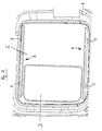
- das zusammengesetzte Bauteil gemäß Fig. 2 in einer Draufsicht,
- Fig. 4
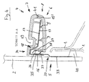
- einen Schnitt längs der Linie A-A in Fig. 3,
- Fig. 5
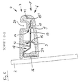
- einen Schnitt längs der Linie B-B in Fig. 3 und
- Fig. 6
- einen Schnitt längs der Linie C-C in Fig. 3.
- In Fig. 1 ist ein Teil einer Karosserie 1 eines Kraftfahrzeugs gezeigt, in die ein Fenster 2 eingesetzt ist, in dem sich ein bewegliches Fenster 3 befindet. Das feste Fenster 2 weist in seinem oberen und in seinem unteren Bereich jeweils eine Führungsschiene 4 auf, deren Fänger 5 mit dem festen Fenster 2 verklebt sind. Die in Fig. 1 gezeigte Führungsschiene 4 verläuft horizontal. In anderen Anwendungsfällen kann die Führungsschiene 4 schräg verlaufen.
- Wie in Fig. 2 dargestellt umfaßt die Führungsschiene 4, eine Unterschale 6 aus Kunststoff, eine Oberschale 7 aus Kunststoff und einen Einleger 8 aus Stahl bzw. Stahlblech, der im montierten Zustand zwischen der Unterschale 6 und der Oberschale 7 liegt. Die Unterschale 6 weist auf ihrer der Oberschale 7 zugewandten Seite in der aus Fig. 2 ersichtlichen Weise Rippen auf, nämlich Längsrippen 9, 9' und schräg verlaufende Rippen 10, die zickzack-förmig verlaufen.
- Die Längsrippe 9 weist sechs Erhebungen 11 auf, die jeweils einen zugehörigen Längsschlitz 12 des Einlegers 8 durchgreifen. Im Bereich der Enden der Längsrippe 9', die parallel und beabstandet zur Längsrippe 9 verläuft, sind zwei weitere Erhebungen 13 vorgesehen, die entsprechende weitere Längsschlitze 14 im Einleger 8 durchgreifen. Die oberen Enden oder Endbereiche der Erhebungen 11 und weiteren Erhebungen 13 bilden Fügestellen 15, an denen die Unterschale 6 und die Oberschale 7 miteinander verbunden, nämlich vibrationsgeschweißt sind. Weitere Fügestellen 15' werden von den umlaufenden Rändern der Unterschale 6 und der Oberschale 7 gebildet. Auch an diesen Fügestellen 15' sind die Unterschale 6 und die Oberschale 7 miteinander verbunden, nämlich vibrationsgeschweißt.
- Der Einleger 8 weist eine Abwinkelung 16 auf, die mit der ebenen Hauptfläche 17 des Einlegers 8 über eine Abkröpfung 18 verbunden ist. Hauptfläche 17, Abkröpfung 18 und Abwinkelung 16 werden durch Biegen eines Stahlblechs hergestellt. Die ebene Hauptfläche 17 verläuft im Bereich der Mitte zwischen der Unterschale 6 und der Oberschale 7. Die Abkröpfung 18 ist auf der dem feststehenden Fenster 2 zugewandten Seite der Führungsschiene 4 vorgesehen. Sie verläuft zur Oberschale 7 hin. Die Abwinkelung 16 verläuft von dort zur Unterschale 6 hin. Sie ist mit dem feststehenden Fenster 2 verklebt.
- In der Oberschale 7 sind zwei Führungsnuten 19, 20 vorgesehen, in die entsprechende Führungszapfen (in der Zeichnung nicht dargestellt) des beweglichen Fensters 3 eingreifen, die auf diese Weise gleitend geführt sind. An einem Ende jeder Führungsnut 19, 20 ist jeweils ein Reinigungsloch 21, 22 vorhanden, so daß die Führungsnuten 19, 20 selbstreinigend sind und eine dauerhafte Funktion gewährleistet ist.
- Wie aus Fig. 6 ersichtlich sind an der Rippe 9 zwei Ausrichtflächen 23, 24 vorgesehen. Die Ausrichtfläche 23 wird von der rechten Endfläche der Erhebung 11 gebildet. Die Ausrichtfläche 24 wird von der linken Endfläche der Erhebung 11', die der Erhebung 11 rechts benachbart ist, gebildet. Die zugehörigen Ausrichtflächen im Einleger 8 sind die rechte Endfläche des Längsschlitzes 12 und die linke Endfläche des Längsschlitzes 12', der dem Längsschlitz 12 auf der rechten Seite benachbart ist. Der Bereich 25 des Einlegers 8 zwischen den Längsschlitzen 12 und 12' liegt in der aus Fig. 6 ersichtlichen Weise zwischen den Ausrichtflächen 23 und 24 in der Unterschale 6. Dabei ist der Abstand der Ausrichtflächen 23 und 24 voneinander genauso groß wie die Länge des Bereichs 25, so daß der Bereich 25 spielfrei zwischen den Ausrichtflächen 23 und 24 liegt.
- Der auf der rechten Seite nächste Bereich 26 des Einlegers 8 zwischen den Längsschlitzen 12' und 12" ist etwas kürzer als der Abstand der rechten Endfläche 27 der Erhebung 11' und der linken Endfläche 28 der Erhebung 11". Auf diese Weise werden zwischen den Enden des Bereichs 26 und den angrenzenden Endflächen 27 und 28 Ausgleichsfugen 29 und 30 geschaffen, durch die unterschiedliche Wärmedehnungen der einzelnen Teile, also der Unterschale 6, der Oberschale 7 und des Einlegers 8, ausgeglichen werden können.
- Den Erhebungen 11, 11', 11 " liegen entsprechende Erhebungen 31, 31' und 31" der Oberschale 7, die an Rippen der Oberschale 7 ausgebildet sein können, gegenüber. Die Fügestellen 15 befinden sich im Überlappungsbereich der Erhebungen 11, 11', 11" und 31, 31', 31". Zwischen den Erhebungen 31, 31' und 31" der Oberschale 7 sind Vertiefungen 32 vorgesehen.
- Die Führungsschiene 4 ist mit dem festen Fenster 2 verbunden, nämlich verklebt. Eine Absicherung wird durch zwei Fänger 5 bewirkt, die mit der Karosserie 1 durch eine Verklebung 40 verbunden sind und die eine Anlagefläche 33 und ein Clipsteil 34 aufweisen. Das Clipsteil 34 umfaßt eine nach oben weisende Lasche 35, von der ein Haken 36 abgekantet ist, und ein Klemmteil 37, das in dieselbe Richtung wie der Haken 36 weist und das aus dem mittleren Bereich der Lasche 35 herausgebogen ist. Das Clipsteil 34 wird zwischen die Abwinklung 16 des Einlegers 8 und die hintere Endwand 37 der Unterschale 6 eingeklemmt, wie in Fig. 4 dargestellt. Hierzu weist die hintere Endwand 37 einen Absatz 38 auf, der vom Ende des Hakens 36 hintergriffen wird.
- Das Clipsteil 34 ist mit der Anlagefläche 33 des Fängers 5 durch eine Abkröpfung 39 verbunden. Die Anlagefläche 33 liegt an dem festen Fenster 2 an. Sie ist in ihrem unteren Endbereich mit dem festen Fenster 2 verklebt, und zwar durch dieselbe Verklebung 40, mittels der das feste Fenster 2 mit der Karosserie 1 verklebt ist. Durch die Verklebung 40 ist ferner die Anlagefläche 33 des Clipsteils 34 des Fängers 5 mit der Karosserie 1 verklebt.
- Die Unterschale 6 und die Oberschale 7 sind in ihren äußeren Endbereichen durch eine weitere Fügestelle 41 verbunden, insbesondere verschweißt. Die hintere Endwand 37 der Unterschale 6 weist für jeden Fänger 5 eine Nut 42 auf, deren Tiefe im wesentlichen der Stärke der Lasche 35 entspricht.
- Bei dem geschilderten Ausführungsbeispiel können Eigenspannungen durch Temperaturschwankungen verhindert werden. Hierzu dienen die in Längsrichtung der Führungsschiene 4 verlaufenden Längsschlitze 12, 14 im Einleger 8 und die zugehörigen Erhebungen 11, 13 in der Unterschale 6. Die Fänger 5 verhindern bei einem Bruch des festen Fensters 2 das Eindringen von Teilen der Seitenscheibe 2 und des beweglichen Fensters 3 in den Fahrzeug-Innenraum.
- Das geschilderte Ausführungsbeispiel ermöglicht eine kostengünstige Fertigung durch einfache Werkzeuge. Durch die Verklebungen wird eine spannungsarme Befestigung möglich. Dabei ist eine hohe Stabilität erreichbar. Ferner wird eine hohe Designfreiheit ermöglicht, da zusätzliche Verkleidungen überflüssig sind, so daß eine große Designfläche vorhanden ist.
Claims (12)
- Führungsschiene für ein bewegliches Fenster, insbesondere ein Schiebefenster (3), eines Kraftfahrzeugs, mit einer Unterschale (6), einer Oberschale (7) und einem Einleger (8) zwischen der Unterschale (6) und der Oberschale (7),
dadurch gekennzeichnet,
daß die Unterschale (6) und die Oberschale (7) an Fügestellen (15, 41) miteinander verbunden sind und daß die Oberschale (7) und/oder die Unterschale (6) eine oder mehrere Führungsbahnen, insbesondere Führungsnuten (19, 20), für ein bewegliches Fenster oder Schiebefenster (3) aufweisen. - Führungsschiene nach Anspruch 1, dadurch gekennzeichnet, daß die Unterschale (6) und die Oberschale (7) an den Fügestellen (15, 41) durch Verkleben und/oder Verschweißen, vorzugsweise Vibrationsverschweißen, miteinander verbunden sind.
- Führungsschiene nach Anspruch 1 oder 2, dadurch gekennzeichnet, daß die Unterschale (6) und/oder die Oberschale (7) Rippen (9, 9', 10) aufweisen.
- Führungsschiene nach einem der vorhergehenden Ansprüche, dadurch gekennzeichnet, daß die Fügestellen (15, 15') an den umlaufenden Rändern der Unterschale (6) und der Oberschale (7) und/oder an den Rippen (9, 9', 10) liegen.
- Führungsschiene nach einem der vorhergehenden Ansprüche, dadurch gekennzeichnet, daß der Einleger (8) Durchbrechungen aufweist.
- Führungsschiene nach Anspruch 5, dadurch gekennzeichnet, daß die Durchbrechungen als Schlitze (12, 12', 12", 14) ausgebildet sind.
- Führungsschiene nach Anspruch 5 oder 6, dadurch gekennzeichnet, daß die Durchbrechungen bzw. Schlitze (12, 12', 12", 14) von Fügestellen oder Erhebungen (11, 11', 11", 13), an denen Fügestellen (15) liegen, durchgriffen werden.
- Führungsschiene nach einem der Ansprüche 5 bis 7, dadurch gekennzeichnet, daß an einer oder mehreren Durchbrechungen bzw. Schlitzen (12, 12') und/oder an einer oder mehreren Fügestellen bzw. Erhebungen (11, 11') Ausrichtflächen (23, 24) vorgesehen sind.
- Führungsschiene nach einem der Ansprüche 5 bis 8, dadurch gekennzeichnet, daß an einer oder mehreren Durchbrechungen bzw. Schlitzen (12', 12") und/oder an einer oder mehreren Fügestellen bzw. Erhebungen (11', 11") Ausgleichsfugen (29, 30) vorgesehen sind.
- Führungsschiene nach einem der vorhergehenden Ansprüche, dadurch gekennzeichnet, daß der Einleger (8) eine Abwinkelung (16) aufweist.
- Führungsschiene nach einem der vorhergehenden Ansprüche, gekennzeichnet durch einen Fänger (5), der mit der Führungsschiene (4) verbindbar ist.
- Führungsschiene nach einem der vorhergehenden Ansprüche, dadurch gekennzeichnet, daß in der oder den Führungsbahnen bzw. Führungsnuten (19, 20) eines oder mehrere Reinigungslöcher (21, 22) vorgesehen sind.
Applications Claiming Priority (2)
| Application Number | Priority Date | Filing Date | Title |
|---|---|---|---|
| DE10343216 | 2003-09-18 | ||
| DE10343216A DE10343216A1 (de) | 2003-09-18 | 2003-09-18 | Zusammengesetztes Bauteil, insbesondere für ein Schiebefenster eines Kraftfahrzeugs |
Publications (2)
| Publication Number | Publication Date |
|---|---|
| EP1516990A1 EP1516990A1 (de) | 2005-03-23 |
| EP1516990B1 true EP1516990B1 (de) | 2006-12-20 |
Family
ID=34177811
Family Applications (1)
| Application Number | Title | Priority Date | Filing Date |
|---|---|---|---|
| EP04021818A Expired - Lifetime EP1516990B1 (de) | 2003-09-18 | 2004-09-14 | Zusammengesetztes Bauteil, insbesondere für ein Schiebefenster eines Kraftfahrzeugs |
Country Status (5)
| Country | Link |
|---|---|
| US (1) | US7980027B2 (de) |
| EP (1) | EP1516990B1 (de) |
| AT (1) | ATE348935T1 (de) |
| DE (2) | DE10343216A1 (de) |
| ES (1) | ES2276202T3 (de) |
Families Citing this family (15)
| Publication number | Priority date | Publication date | Assignee | Title |
|---|---|---|---|---|
| PL2324177T3 (pl) * | 2008-09-19 | 2014-07-31 | Ship Car S R L | Urządzenie do przemieszczania i zestaw |
| EP2189313B1 (de) | 2008-11-20 | 2012-07-04 | Advanced Comfort Systems France SAS - ACS France | Vorrichtung zum Verschließen einer Öffnung eines Kraftfahrzeugs, die mit einem Halterungselement ausgestattet ist, das durch Kleben befestigt ist, entsprechendes Verfahren und Fahrzeug |
| FR2938473B1 (fr) * | 2008-11-20 | 2012-11-30 | Wagons Sas | Dispositif d'obturation d'une baie menagee dans un vehicule automobile, a element de retenue rapporte par collage, procede et vehicule correspondant |
| FR2964347B1 (fr) * | 2010-09-02 | 2012-09-28 | Faurecia Interieur Ind | Module de porte de vehicule automobile comprenant un systeme leve-vitre |
| US9433306B2 (en) * | 2011-01-26 | 2016-09-06 | Syneron Medical Ltd. | Support apparatus and method for a sliding frame |
| US8776435B2 (en) * | 2012-07-03 | 2014-07-15 | Magna Mirrors Of America, Inc. | Window assembly for vehicle |
| US9470028B2 (en) | 2013-05-06 | 2016-10-18 | Gregory A. Header | Sliding door assembly |
| US11280114B2 (en) * | 2017-09-29 | 2022-03-22 | Arow Global Corp. | Friction latch for sliding sash window |
| US10822863B2 (en) | 2018-05-02 | 2020-11-03 | Pella Corporation | Sliding fenestration unit with coplanar panels |
| CA3066592C (en) | 2019-01-09 | 2023-06-13 | Pella Corporation | Slide and pivot fenestration unit |
| US11286709B2 (en) | 2019-11-06 | 2022-03-29 | Pella Corporation | Coplanar bi-fold and sliding door |
| US12416189B1 (en) | 2024-03-13 | 2025-09-16 | Pella Corporation | Fenestration system with head slide |
| US12637887B2 (en) | 2024-03-13 | 2026-05-26 | Pella Corporation | Fenestration system with screen carrier |
| US12624589B2 (en) | 2024-03-13 | 2026-05-12 | Pella Corporation | Locking and height-adjustable pivot rider |
| US12650045B1 (en) * | 2025-01-30 | 2026-06-09 | Jeld-Wen, Inc. | Fenestration unit with sash supported for gliding movement and lateral movement within a frame |
Family Cites Families (27)
| Publication number | Priority date | Publication date | Assignee | Title |
|---|---|---|---|---|
| US1637367A (en) * | 1924-03-26 | 1927-08-02 | Joseph B Zimmers | Automobile inclosure structure |
| US2409711A (en) * | 1944-06-23 | 1946-10-22 | Nat Lock Washer Co | Sash lock for bus or car window construction |
| US3564204A (en) * | 1966-06-06 | 1971-02-16 | Siemens Ag | Apparatus for controlling the heating current for welding thermoplastic synthetics |
| US4222427A (en) * | 1978-02-21 | 1980-09-16 | John Buchner | Trim units for valances, doors and the like |
| DE2841177A1 (de) * | 1978-09-21 | 1980-04-17 | Maschf Augsburg Nuernberg Ag | Personenfahrzeug mit eingeklebten fensterscheiben |
| US4208755A (en) * | 1979-02-05 | 1980-06-24 | Shepherd L Clay | Track wiper for sliding shower door assembly |
| US4281480A (en) * | 1979-06-21 | 1981-08-04 | U.S. Gypsum Company | Doorframe construction |
| JPS5914579A (ja) * | 1982-07-16 | 1984-01-25 | Nissan Motor Co Ltd | スライドドア型車の横桁構造材補強構造 |
| US4601927A (en) * | 1984-05-11 | 1986-07-22 | Hydroacoustics, Inc. | Welding of plastic parts |
| IT1183758B (it) * | 1985-02-15 | 1987-10-22 | Comind Spa Azienda Ages | Cristallo fisso per autoveicoli e suo metodo di collegamento diretto e reversibile alla scocca dell'autoveicolo |
| US4635420A (en) * | 1985-04-22 | 1987-01-13 | Almac Plastics Inc. | Motor vehicle glazing assembly and method of manufacture thereof |
| DE4340013A1 (de) * | 1993-11-24 | 1995-06-01 | Brose Fahrzeugteile | Elektrisch angetriebene Verstellvorrichtung für Fensterscheiben oder Schiebedächer von Kraftfahrzeugen |
| US5467557A (en) * | 1993-12-15 | 1995-11-21 | Jones; Edgar W. | Window construction and method of making the same |
| JP3273690B2 (ja) * | 1994-03-24 | 2002-04-08 | 株式会社ニフコ | ガラスホルダー |
| US5442880A (en) * | 1994-05-09 | 1995-08-22 | Excel Industries, Inc. | Window assembly with slider |
| US6058654A (en) * | 1994-06-10 | 2000-05-09 | Rissone; Robert | Method and system for sealing around a door |
| FR2742099B1 (fr) | 1995-12-08 | 1998-01-02 | Farnier & Penin | Dispositif de fermeture affleurant d'une baie de vehicule automobile |
| DE19835877B4 (de) * | 1997-08-07 | 2006-03-09 | Kabushiki Kaisha Toyota Jidoshokki, Kariya | Fahrzeugfenster |
| FR2778608B1 (fr) | 1998-05-14 | 2000-09-29 | Wagon Automotive | Dispositif d'obturation d'une baie menagee dans la carosserie d'un vehicule, et procede de fabrication et de montage correspondant |
| ES2224489T5 (es) | 1998-07-03 | 2011-10-10 | DURA AUTOMOTIVE BODY & GLASS SYSTEMS GMBH | Ventana de corredera para una puerta de un vehículo. |
| FR2787498B1 (fr) | 1998-12-21 | 2001-08-10 | Euramax Ind Sa | Dispositif de securite pour baie vitree a volet mobile |
| DE19916619C2 (de) * | 1999-04-13 | 2001-11-22 | Schade Plettenberg Glasmodule | Zusammengesetztes Bauteil |
| DE10036813C1 (de) * | 2000-03-28 | 2001-09-06 | Kuester Automotive Door Sys | Schließkraft-Meßvorrichtung für Fensterheber |
| DE10122637B4 (de) * | 2001-03-16 | 2005-07-21 | Wagon Automotive Gmbh | Dichtungsanordnung für eine Kraftfahrzeugtüre und/oder ein Kraftfahrzeugfenster |
| FR2833209B1 (fr) | 2001-12-10 | 2005-06-24 | Wagon Automotive Snc | Dispositif d'obturation d'une baie menagee dans la carrosserie d'un vehicule, et vehicule correspondant |
| US7003916B2 (en) * | 2002-04-01 | 2006-02-28 | Donnelly Corporation | Horizontal slider window assembly |
| US6925767B2 (en) * | 2002-10-09 | 2005-08-09 | Odl, Incorporated | Screwless window frame assembly |
-
2003
- 2003-09-18 DE DE10343216A patent/DE10343216A1/de not_active Withdrawn
-
2004
- 2004-09-14 DE DE502004002359T patent/DE502004002359D1/de not_active Expired - Lifetime
- 2004-09-14 EP EP04021818A patent/EP1516990B1/de not_active Expired - Lifetime
- 2004-09-14 AT AT04021818T patent/ATE348935T1/de not_active IP Right Cessation
- 2004-09-14 ES ES04021818T patent/ES2276202T3/es not_active Expired - Lifetime
- 2004-09-20 US US10/945,458 patent/US7980027B2/en not_active Expired - Fee Related
Also Published As
| Publication number | Publication date |
|---|---|
| US7980027B2 (en) | 2011-07-19 |
| DE502004002359D1 (de) | 2007-02-01 |
| DE10343216A1 (de) | 2005-04-14 |
| ES2276202T3 (es) | 2007-06-16 |
| EP1516990A1 (de) | 2005-03-23 |
| ATE348935T1 (de) | 2007-01-15 |
| US20050210751A1 (en) | 2005-09-29 |
Similar Documents
| Publication | Publication Date | Title |
|---|---|---|
| DE69702676T2 (de) | Kraftfahrzeug-Innenbekleidung | |
| EP1729387B1 (de) | Befestigungsvorrichtung für eine Leitung | |
| DE102008021717B4 (de) | Dachfugenleiste mit geformtem Ende | |
| EP1516990A1 (de) | Zusammengesetztes Bauteil, insbesondere für ein Schiebefenster eines Kraftfahrzeugs | |
| DE4106158C2 (de) | Befestigungsvorrichtung für einen Kraftfahrzeug-Kühlergrill | |
| DE202008007783U1 (de) | In einem Loch befestigbares Halteelement | |
| DE602005002868T2 (de) | Kraftfahrzeugrahmenanordnung | |
| DE102008005575A1 (de) | Kraftfahrzugschloss und Schlossgehäuse | |
| DE102008038848A1 (de) | Seitenteil für einen Sitzträger eines Fahrzeugsitzes, sowie Sitzträger | |
| DE102022126005A1 (de) | Befestigungsklammer, Befestigungssystem und Dachanordnung | |
| EP4048111B1 (de) | Zierleiste und steckverbindung für eine kraftfahrzeugkarosserie | |
| DE102017116744A1 (de) | Obere Fahrzeugkarosseriestruktur | |
| EP1875107B1 (de) | Zugmitteltrieb mit zumindest einer schiene zum spannen und/oder führen eines endlosen zugmittels | |
| DE10122637B4 (de) | Dichtungsanordnung für eine Kraftfahrzeugtüre und/oder ein Kraftfahrzeugfenster | |
| DE102019133413B4 (de) | Befestigungseinrichtung für eine Wasserfangleiste und Anordnung einer Wasserfangleiste an einer A-Säule eines Kraftfahrzeugs | |
| DE202010004995U1 (de) | Befestiger zur Befestigung eines ersten Bauteils an einem zweiten Bauteil | |
| EP1827882B1 (de) | Spiegelmodul, insbesondere für ein fahrzeug, komponente, die das spiegelmodul aufweist, komponente, insbesondere sonnenblende und insbesondere für ein fahrzeug, verfahren zur montage des spiegelmoduls, verfahren zur montage der komponente und verwendung der komponente als sonnenblende eines kraftfahrzeugs | |
| DE102021213191A1 (de) | Fahrzeugtür und Schachtleiste dafür | |
| EP0978661A2 (de) | Kraftschluss-Verbindung | |
| DE102017106727A1 (de) | Verfahren zur Verbindung von drei Bauteilen und verbindbares System zur Durchführung des Verfahrens | |
| EP1911542B1 (de) | Bauelement mit zwei senkrecht zueinander stehenden Blechplatten | |
| DE102004003907B4 (de) | Klips | |
| DE10255151A1 (de) | Seitenscheibe für ein Fahrzeug, insbesondere einen Personenkraftwagen | |
| DE202009010957U1 (de) | Montageaufbau eines teleskopischen Schutzdeckels | |
| DE102008060356B4 (de) | Kraftfahrzeugkarosserie |
Legal Events
| Date | Code | Title | Description |
|---|---|---|---|
| PUAI | Public reference made under article 153(3) epc to a published international application that has entered the european phase |
Free format text: ORIGINAL CODE: 0009012 |
|
| AK | Designated contracting states |
Kind code of ref document: A1 Designated state(s): AT BE BG CH CY CZ DE DK EE ES FI FR GB GR HU IE IT LI LU MC NL PL PT RO SE SI SK TR |
|
| AX | Request for extension of the european patent |
Extension state: AL HR LT LV MK |
|
| 17P | Request for examination filed |
Effective date: 20050520 |
|
| 17Q | First examination report despatched |
Effective date: 20050704 |
|
| AKX | Designation fees paid |
Designated state(s): AT BE BG CH CY CZ DE DK EE ES FI FR GB GR HU IE IT LI LU MC NL PL PT RO SE SI SK TR |
|
| GRAP | Despatch of communication of intention to grant a patent |
Free format text: ORIGINAL CODE: EPIDOSNIGR1 |
|
| RAP1 | Party data changed (applicant data changed or rights of an application transferred) |
Owner name: DURA AUTOMOTIVE PLETTENBERG ENTWICKLUNGS- UND VERT |
|
| GRAS | Grant fee paid |
Free format text: ORIGINAL CODE: EPIDOSNIGR3 |
|
| GRAA | (expected) grant |
Free format text: ORIGINAL CODE: 0009210 |
|
| AK | Designated contracting states |
Kind code of ref document: B1 Designated state(s): AT BE BG CH CY CZ DE DK EE ES FI FR GB GR HU IE IT LI LU MC NL PL PT RO SE SI SK TR |
|
| PG25 | Lapsed in a contracting state [announced via postgrant information from national office to epo] |
Ref country code: IT Free format text: LAPSE BECAUSE OF FAILURE TO SUBMIT A TRANSLATION OF THE DESCRIPTION OR TO PAY THE FEE WITHIN THE PRESCRIBED TIME-LIMIT;WARNING: LAPSES OF ITALIAN PATENTS WITH EFFECTIVE DATE BEFORE 2007 MAY HAVE OCCURRED AT ANY TIME BEFORE 2007. THE CORRECT EFFECTIVE DATE MAY BE DIFFERENT FROM THE ONE RECORDED. Effective date: 20061220 Ref country code: SK Free format text: LAPSE BECAUSE OF FAILURE TO SUBMIT A TRANSLATION OF THE DESCRIPTION OR TO PAY THE FEE WITHIN THE PRESCRIBED TIME-LIMIT Effective date: 20061220 Ref country code: SI Free format text: LAPSE BECAUSE OF FAILURE TO SUBMIT A TRANSLATION OF THE DESCRIPTION OR TO PAY THE FEE WITHIN THE PRESCRIBED TIME-LIMIT Effective date: 20061220 Ref country code: FI Free format text: LAPSE BECAUSE OF FAILURE TO SUBMIT A TRANSLATION OF THE DESCRIPTION OR TO PAY THE FEE WITHIN THE PRESCRIBED TIME-LIMIT Effective date: 20061220 Ref country code: CZ Free format text: LAPSE BECAUSE OF FAILURE TO SUBMIT A TRANSLATION OF THE DESCRIPTION OR TO PAY THE FEE WITHIN THE PRESCRIBED TIME-LIMIT Effective date: 20061220 Ref country code: RO Free format text: LAPSE BECAUSE OF FAILURE TO SUBMIT A TRANSLATION OF THE DESCRIPTION OR TO PAY THE FEE WITHIN THE PRESCRIBED TIME-LIMIT Effective date: 20061220 Ref country code: PL Free format text: LAPSE BECAUSE OF FAILURE TO SUBMIT A TRANSLATION OF THE DESCRIPTION OR TO PAY THE FEE WITHIN THE PRESCRIBED TIME-LIMIT Effective date: 20061220 Ref country code: IE Free format text: LAPSE BECAUSE OF FAILURE TO SUBMIT A TRANSLATION OF THE DESCRIPTION OR TO PAY THE FEE WITHIN THE PRESCRIBED TIME-LIMIT Effective date: 20061220 Ref country code: NL Free format text: LAPSE BECAUSE OF FAILURE TO SUBMIT A TRANSLATION OF THE DESCRIPTION OR TO PAY THE FEE WITHIN THE PRESCRIBED TIME-LIMIT Effective date: 20061220 Ref country code: DK Free format text: LAPSE BECAUSE OF FAILURE TO SUBMIT A TRANSLATION OF THE DESCRIPTION OR TO PAY THE FEE WITHIN THE PRESCRIBED TIME-LIMIT Effective date: 20061220 |
|
| REG | Reference to a national code |
Ref country code: GB Ref legal event code: FG4D Free format text: NOT ENGLISH |
|
| REG | Reference to a national code |
Ref country code: CH Ref legal event code: EP |
|
| REF | Corresponds to: |
Ref document number: 502004002359 Country of ref document: DE Date of ref document: 20070201 Kind code of ref document: P |
|
| REG | Reference to a national code |
Ref country code: IE Ref legal event code: FG4D Free format text: LANGUAGE OF EP DOCUMENT: GERMAN |
|
| PG25 | Lapsed in a contracting state [announced via postgrant information from national office to epo] |
Ref country code: BG Free format text: LAPSE BECAUSE OF FAILURE TO SUBMIT A TRANSLATION OF THE DESCRIPTION OR TO PAY THE FEE WITHIN THE PRESCRIBED TIME-LIMIT Effective date: 20070320 Ref country code: SE Free format text: LAPSE BECAUSE OF FAILURE TO SUBMIT A TRANSLATION OF THE DESCRIPTION OR TO PAY THE FEE WITHIN THE PRESCRIBED TIME-LIMIT Effective date: 20070320 |
|
| GBT | Gb: translation of ep patent filed (gb section 77(6)(a)/1977) |
Effective date: 20070321 |
|
| PG25 | Lapsed in a contracting state [announced via postgrant information from national office to epo] |
Ref country code: PT Free format text: LAPSE BECAUSE OF FAILURE TO SUBMIT A TRANSLATION OF THE DESCRIPTION OR TO PAY THE FEE WITHIN THE PRESCRIBED TIME-LIMIT Effective date: 20070424 |
|
| ET | Fr: translation filed | ||
| NLV1 | Nl: lapsed or annulled due to failure to fulfill the requirements of art. 29p and 29m of the patents act | ||
| REG | Reference to a national code |
Ref country code: ES Ref legal event code: FG2A Ref document number: 2276202 Country of ref document: ES Kind code of ref document: T3 |
|
| PLBI | Opposition filed |
Free format text: ORIGINAL CODE: 0009260 |
|
| PLAX | Notice of opposition and request to file observation + time limit sent |
Free format text: ORIGINAL CODE: EPIDOSNOBS2 |
|
| 26 | Opposition filed |
Opponent name: WAGON SAS Effective date: 20070920 |
|
| PLAF | Information modified related to communication of a notice of opposition and request to file observations + time limit |
Free format text: ORIGINAL CODE: EPIDOSCOBS2 |
|
| BERE | Be: lapsed |
Owner name: DURA AUTOMOTIVE PLETTENBERG ENTWICKLUNGS- UND VER Effective date: 20070930 |
|
| PLBB | Reply of patent proprietor to notice(s) of opposition received |
Free format text: ORIGINAL CODE: EPIDOSNOBS3 |
|
| PG25 | Lapsed in a contracting state [announced via postgrant information from national office to epo] |
Ref country code: MC Free format text: LAPSE BECAUSE OF NON-PAYMENT OF DUE FEES Effective date: 20070930 Ref country code: GR Free format text: LAPSE BECAUSE OF FAILURE TO SUBMIT A TRANSLATION OF THE DESCRIPTION OR TO PAY THE FEE WITHIN THE PRESCRIBED TIME-LIMIT Effective date: 20070321 |
|
| PG25 | Lapsed in a contracting state [announced via postgrant information from national office to epo] |
Ref country code: BE Free format text: LAPSE BECAUSE OF NON-PAYMENT OF DUE FEES Effective date: 20070930 |
|
| PG25 | Lapsed in a contracting state [announced via postgrant information from national office to epo] |
Ref country code: AT Free format text: LAPSE BECAUSE OF NON-PAYMENT OF DUE FEES Effective date: 20070914 |
|
| PG25 | Lapsed in a contracting state [announced via postgrant information from national office to epo] |
Ref country code: EE Free format text: LAPSE BECAUSE OF FAILURE TO SUBMIT A TRANSLATION OF THE DESCRIPTION OR TO PAY THE FEE WITHIN THE PRESCRIBED TIME-LIMIT Effective date: 20061220 |
|
| REG | Reference to a national code |
Ref country code: CH Ref legal event code: PL |
|
| PG25 | Lapsed in a contracting state [announced via postgrant information from national office to epo] |
Ref country code: CH Free format text: LAPSE BECAUSE OF NON-PAYMENT OF DUE FEES Effective date: 20070930 Ref country code: LI Free format text: LAPSE BECAUSE OF NON-PAYMENT OF DUE FEES Effective date: 20070930 |
|
| PG25 | Lapsed in a contracting state [announced via postgrant information from national office to epo] |
Ref country code: LU Free format text: LAPSE BECAUSE OF NON-PAYMENT OF DUE FEES Effective date: 20070914 Ref country code: CY Free format text: LAPSE BECAUSE OF FAILURE TO SUBMIT A TRANSLATION OF THE DESCRIPTION OR TO PAY THE FEE WITHIN THE PRESCRIBED TIME-LIMIT Effective date: 20061220 |
|
| PG25 | Lapsed in a contracting state [announced via postgrant information from national office to epo] |
Ref country code: TR Free format text: LAPSE BECAUSE OF FAILURE TO SUBMIT A TRANSLATION OF THE DESCRIPTION OR TO PAY THE FEE WITHIN THE PRESCRIBED TIME-LIMIT Effective date: 20061220 Ref country code: HU Free format text: LAPSE BECAUSE OF FAILURE TO SUBMIT A TRANSLATION OF THE DESCRIPTION OR TO PAY THE FEE WITHIN THE PRESCRIBED TIME-LIMIT Effective date: 20070621 |
|
| PG25 | Lapsed in a contracting state [announced via postgrant information from national office to epo] |
Ref country code: CH Free format text: LAPSE BECAUSE OF NON-PAYMENT OF DUE FEES Effective date: 20080930 Ref country code: LI Free format text: LAPSE BECAUSE OF NON-PAYMENT OF DUE FEES Effective date: 20080930 |
|
| PLBD | Termination of opposition procedure: decision despatched |
Free format text: ORIGINAL CODE: EPIDOSNOPC1 |
|
| PLBP | Opposition withdrawn |
Free format text: ORIGINAL CODE: 0009264 |
|
| PLBM | Termination of opposition procedure: date of legal effect published |
Free format text: ORIGINAL CODE: 0009276 |
|
| STAA | Information on the status of an ep patent application or granted ep patent |
Free format text: STATUS: OPPOSITION PROCEDURE CLOSED |
|
| 27C | Opposition proceedings terminated |
Effective date: 20110124 |
|
| REG | Reference to a national code |
Ref country code: FR Ref legal event code: PLFP Year of fee payment: 13 |
|
| PGFP | Annual fee paid to national office [announced via postgrant information from national office to epo] |
Ref country code: ES Payment date: 20160926 Year of fee payment: 13 |
|
| REG | Reference to a national code |
Ref country code: DE Ref legal event code: R082 Ref document number: 502004002359 Country of ref document: DE Representative=s name: LORENZ SEIDLER GOSSEL RECHTSANWAELTE PATENTANW, DE Ref country code: DE Ref legal event code: R081 Ref document number: 502004002359 Country of ref document: DE Owner name: DURA AUTOMOTIVE HOLDINGS U.K., LTD., CASTLE VA, GB Free format text: FORMER OWNER: DURA AUTOMOTIVE PLETTENBERG ENTWICKLUNGS- UND VERTRIEBS GMBH, 58840 PLETTENBERG, DE |
|
| REG | Reference to a national code |
Ref country code: GB Ref legal event code: 732E Free format text: REGISTERED BETWEEN 20170601 AND 20170607 |
|
| REG | Reference to a national code |
Ref country code: FR Ref legal event code: TP Owner name: DURA AUTOMOTIVE BODY & GLASS SYSTEMS GMBH, DE Effective date: 20170629 |
|
| REG | Reference to a national code |
Ref country code: GB Ref legal event code: 732E Free format text: REGISTERED BETWEEN 20170727 AND 20170802 |
|
| REG | Reference to a national code |
Ref country code: FR Ref legal event code: PLFP Year of fee payment: 14 |
|
| REG | Reference to a national code |
Ref country code: FR Ref legal event code: PLFP Year of fee payment: 15 |
|
| REG | Reference to a national code |
Ref country code: ES Ref legal event code: FD2A Effective date: 20181024 |
|
| PGFP | Annual fee paid to national office [announced via postgrant information from national office to epo] |
Ref country code: FR Payment date: 20180925 Year of fee payment: 15 Ref country code: DE Payment date: 20180927 Year of fee payment: 15 |
|
| PGFP | Annual fee paid to national office [announced via postgrant information from national office to epo] |
Ref country code: GB Payment date: 20180927 Year of fee payment: 15 |
|
| PG25 | Lapsed in a contracting state [announced via postgrant information from national office to epo] |
Ref country code: ES Free format text: LAPSE BECAUSE OF NON-PAYMENT OF DUE FEES Effective date: 20170915 |
|
| REG | Reference to a national code |
Ref country code: DE Ref legal event code: R119 Ref document number: 502004002359 Country of ref document: DE |
|
| PG25 | Lapsed in a contracting state [announced via postgrant information from national office to epo] |
Ref country code: DE Free format text: LAPSE BECAUSE OF NON-PAYMENT OF DUE FEES Effective date: 20200401 |
|
| GBPC | Gb: european patent ceased through non-payment of renewal fee |
Effective date: 20190914 |
|
| PG25 | Lapsed in a contracting state [announced via postgrant information from national office to epo] |
Ref country code: FR Free format text: LAPSE BECAUSE OF NON-PAYMENT OF DUE FEES Effective date: 20190930 Ref country code: GB Free format text: LAPSE BECAUSE OF NON-PAYMENT OF DUE FEES Effective date: 20190914 |