EP1516580A1 - Handgelenk-Haltevorrichtung für Pulswellenmessgerät - Google Patents
Handgelenk-Haltevorrichtung für Pulswellenmessgerät Download PDFInfo
- Publication number
- EP1516580A1 EP1516580A1 EP04021910A EP04021910A EP1516580A1 EP 1516580 A1 EP1516580 A1 EP 1516580A1 EP 04021910 A EP04021910 A EP 04021910A EP 04021910 A EP04021910 A EP 04021910A EP 1516580 A1 EP1516580 A1 EP 1516580A1
- Authority
- EP
- European Patent Office
- Prior art keywords
- wrist
- pulse wave
- measuring apparatus
- wave measuring
- holding portion
- Prior art date
- Legal status (The legal status is an assumption and is not a legal conclusion. Google has not performed a legal analysis and makes no representation as to the accuracy of the status listed.)
- Withdrawn
Links
- 210000000707 wrist Anatomy 0.000 title claims abstract description 314
- 238000000034 method Methods 0.000 claims description 21
- 210000002321 radial artery Anatomy 0.000 claims description 13
- 238000001361 intraarterial administration Methods 0.000 claims description 8
- 239000003550 marker Substances 0.000 claims description 6
- 230000000737 periodic effect Effects 0.000 claims description 6
- 210000003857 wrist joint Anatomy 0.000 claims description 4
- 238000005259 measurement Methods 0.000 description 46
- 239000000463 material Substances 0.000 description 11
- 210000000245 forearm Anatomy 0.000 description 8
- 210000000623 ulna Anatomy 0.000 description 4
- 210000001367 artery Anatomy 0.000 description 3
- 230000018109 developmental process Effects 0.000 description 2
- 239000004065 semiconductor Substances 0.000 description 2
- 206010003210 Arteriosclerosis Diseases 0.000 description 1
- 206010007572 Cardiac hypertrophy Diseases 0.000 description 1
- 208000006029 Cardiomegaly Diseases 0.000 description 1
- 206010020772 Hypertension Diseases 0.000 description 1
- 208000032382 Ischaemic stroke Diseases 0.000 description 1
- 230000032683 aging Effects 0.000 description 1
- 208000011775 arteriosclerosis disease Diseases 0.000 description 1
- 230000036772 blood pressure Effects 0.000 description 1
- 210000004204 blood vessel Anatomy 0.000 description 1
- 238000001514 detection method Methods 0.000 description 1
- 238000010586 diagram Methods 0.000 description 1
- 201000010099 disease Diseases 0.000 description 1
- 208000037265 diseases, disorders, signs and symptoms Diseases 0.000 description 1
- 238000006073 displacement reaction Methods 0.000 description 1
- 230000000694 effects Effects 0.000 description 1
- 210000003205 muscle Anatomy 0.000 description 1
- 208000031225 myocardial ischemia Diseases 0.000 description 1
- 238000002559 palpation Methods 0.000 description 1
- 230000002093 peripheral effect Effects 0.000 description 1
- 239000012209 synthetic fiber Substances 0.000 description 1
- 229920002994 synthetic fiber Polymers 0.000 description 1
- 238000004804 winding Methods 0.000 description 1
Images








Classifications
-
- A—HUMAN NECESSITIES
- A61—MEDICAL OR VETERINARY SCIENCE; HYGIENE
- A61B—DIAGNOSIS; SURGERY; IDENTIFICATION
- A61B5/00—Measuring for diagnostic purposes; Identification of persons
- A61B5/02—Detecting, measuring or recording for evaluating the cardiovascular system, e.g. pulse, heart rate, blood pressure or blood flow
- A61B5/021—Measuring pressure in heart or blood vessels
-
- A—HUMAN NECESSITIES
- A61—MEDICAL OR VETERINARY SCIENCE; HYGIENE
- A61B—DIAGNOSIS; SURGERY; IDENTIFICATION
- A61B5/00—Measuring for diagnostic purposes; Identification of persons
- A61B5/68—Arrangements of detecting, measuring or recording means, e.g. sensors, in relation to patient
- A61B5/6801—Arrangements of detecting, measuring or recording means, e.g. sensors, in relation to patient specially adapted to be attached to or worn on the body surface
- A61B5/6813—Specially adapted to be attached to a specific body part
- A61B5/6824—Arm or wrist
Definitions
- the present invention relates to a wrist securing device for a pulse wave measuring apparatus holding a wrist position in measuring an intra-arterial pressure of a radial artery located under the skin of the wrist, as well as to a pulse wave measuring apparatus equipped with the same.
- a pulse wave measuring apparatus is known as an apparatus to observe such load imposed on the heart or variation in hardening of the wall of an artery.
- the pulse wave measuring apparatus is an apparatus used for measuring a pulse wave by non-invasive detection of an intra-arterial pressure of the radial artery located in a relatively shallow portion under the skin of the wrist.
- the pulse wave refers to periodic fluctuation of a pressure produced in a blood vessel in accordance with heart beat. From analysis of the pulse wave, the load imposed on the heart or variation in hardening of the wall of the artery can be grasped. Therefore, in order to know medical condition of a subject, it is extremely important to measure his/her pulse wave using the pulse wave measuring apparatus.
- a semiconductor pressure sensor utilizing a strain gauge or a diaphragm is commonly used as pressure-sensing means.
- the apparatus is configured such that the pressure-sensing means for detecting the intra-arterial pressure is located on a surface of a sensor unit attached on a wrist.
- a wrist securing device for holding the position of the wrist of the subject is normally used.
- a wrist securing device for a pulse wave measuring apparatus for holding the position of the wrist is disclosed, for example, in Japanese Utility Model Laying-Open No. 3-67605, Japanese Patent Laying-Open Nos. 5-261074 and 11-33007, or the like.
- the wrist securing device for a pulse wave measuring apparatus disclosed in these publications serves to hold the position of the wrist of the subject using a plate-shaped member and a band attached thereto.
- the wrist securing device for a pulse wave measuring apparatus disclosed in Japanese Patent Laying-Open No. 11-33007 will be described by way of example, so as to explain a structure of a conventional wrist securing device for a pulse wave measuring apparatus.
- Fig. 21 shows a structure of a conventional wrist securing device for a pulse wave measuring apparatus disclosed in Japanese Patent Laying-Open No. 11-33007.
- the wrist securing device for a pulse wave measuring apparatus shown in Fig. 21 includes a plate-shaped outer abutment member 110 being in contact with the outer side of a hand 51, a wrist 52 and a forearm 53 and curved so as to secure wrist 52 in a state in which wrist 52 is bent toward a dorsal side; a plate-shaped inner abutment member 120 being in intimate contact with the inner side of fingers and palm of hand 51; a fastening band 130 connecting outer abutment member 110 and inner abutment member 120; and an attachment band 140 for attaching outer abutment member 110 to forearm 53.
- a sensor unit 160 is attached on a palm side portion of wrist 52 using an attachment band 150, so as to perform measurement of the pulse wave.
- the wrist position is stabilized by using the wrist securing device for a pulse wave measuring apparatus, so that the sensor unit can be attached right above the radial artery with higher accuracy.
- the wrist securing device for a pulse wave measuring apparatus for holding the wrist position such that a natural posture of the subject can be maintained without causing pain to him/her. With such a structure, body motion of the subject during measurement is suppressed. Then, the pulse wave can be measured in a stable manner with high accuracy, and an appropriate measurement result can be obtained.
- an object of the present invention is to provide a wrist securing device for a pulse wave measuring apparatus capable of holding a wrist position while maintaining a natural posture of a subject.
- a wrist securing device for a pulse wave measuring apparatus includes a securing base main body mounted on a mount surface, and a holding portion provided in an upper portion of the securing base main body and receiving a wrist with a palm side portion of the wrist facing upward.
- the wrist securing device for a pulse wave measuring apparatus holds the position of the wrist placed on the holding portion for measurement of periodic fluctuation of an intra-arterial pressure of a radial artery located under the skin of the wrist.
- the holding portion has a support surface receiving the wrist in an inclined position so that an end portion on a radial side of the wrist is located above an end portion on an ulnar side thereof while the wrist rests on the holding portion.
- a wrist securing device for a pulse wave measuring apparatus includes a securing base main body mounted on a mount surface, and a holding portion provided in an upper portion of the securing base main body and receiving a wrist with a palm side portion of the wrist facing upward.
- the wrist securing device for a pulse wave measuring apparatus holds the position of the wrist placed on the holding portion for measurement of periodic fluctuation of an intra-arterial pressure of a radial artery located under the skin of the wrist.
- the holding portion has a support surface receiving a dorsal side portion of the wrist while the wrist rests on the holding portion.
- the support surface includes a first support region receiving a radial side portion of the wrist and a second support region receiving an ulnar side portion of the wrist.
- the support surface in a position corresponding to the first support region is structured to incline more gently than the support surface in a position corresponding to the second support region.
- a wrist securing device for a pulse wave measuring apparatus includes a securing base main body mounted on a mount surface, and a holding portion provided in an upper portion of the securing base main body and receiving a wrist with a palm side portion of the wrist facing upward.
- the wrist securing device for a pulse wave measuring apparatus holds the position of the wrist placed on the holding portion for measurement of periodic fluctuation of an intra-arterial pressure of a radial artery located under the skin of the wrist.
- the holding portion has a support surface receiving a dorsal side portion of the wrist while the wrist rests on the holding portion.
- the support surface includes a first support region receiving a radial side portion of the wrist and a second support region receiving an ulnar side portion of the wrist.
- the first support region extends above the second support region.
- a wrist securing device for a pulse wave measuring apparatus includes a securing base main body mounted on a mount surface, and a holding portion provided in an upper portion of the securing base main body and receiving a wrist with a palm side portion of the wrist facing upward.
- the wrist securing device for a pulse wave measuring apparatus holds the position of the wrist placed on the holding portion for measurement of periodic fluctuation of an intra-arterial pressure of the radial artery located under the skin of the wrist.
- the holding portion has a support surface receiving a dorsal side portion of the wrist while the wrist rests on the holding portion.
- the support surface includes a first support region receiving a radial side portion of the wrist and a second support region receiving an ulnar side portion of the wrist.
- the support surface is configured to be asymmetrical around a vertical centerline including a central portion of the support surface in a cross section along a direction in which the first support region and the second support region are aligned.
- the holding portion has a concave portion in a position corresponding to an ulnar styloid process of the wrist while the wrist rests on the holding portion.
- the holding portion has a buffer portion composed of an elastic member in a position corresponding to an ulnar styloid process of the wrist while the wrist rests on the holding portion.
- the holding portion has a right wrist receiving region and a left wrist receiving region.
- the holding portion is configured so as to be switchable between a first state allowing use of the right wrist receiving region and a second state allowing use of the left wrist receiving region.
- the holding portion is attached to the securing base main body in a detachable manner or in a swingable manner.
- the holding portion has a positioning marker in a position corresponding to wrist joint anterior surface stripe located on an outer surface of the wrist while the wrist rests on the holding portion.
- the pulse wave measuring apparatus includes a sensor unit having a pressure-sensing portion and a living body securing device holding a wrist position, and serves to measure the pulse wave by pressing the pressure-sensing portion against the wrist while the wrist is secured by the living body securing device.
- the living body securing device includes any of the wrist securing devices for a pulse wave measuring apparatus described above.
- the wrist position can be held while a natural posture of the subject is maintained. Accordingly, the pulse wave measuring apparatus equipped with the wrist securing device for a pulse wave measuring apparatus as described above is implemented, and stable measurement of the pulse wave with high accuracy is allowed.
- a wrist securing device for a pulse wave measuring apparatus is configured so as to allow a natural posture of a subject while the pulse wave is measured with the pulse wave measuring apparatus, whereby body motion of the subject during measurement is suppressed and the pulse wave is measured in a stable manner with high accuracy.
- the inventor has developed a wrist securing device for a pulse wave measuring apparatus for maintaining a wrist position in a natural posture, instead of maintaining the wrist position of the subject by attaching the attachment band on the hand or the forearm of the subject as in the conventional wrist securing device for a pulse wave measuring apparatus.
- a wrist securing device for a pulse wave measuring apparatus invented in the course of development above will be described.
- a pulse wave measuring apparatus 1X in the related art of the present invention mainly includes a sensor unit 40, a wrist securing device 10X for a pulse wave measuring apparatus serving as a living body securing device, and fastening bands 31, 32.
- Wrist securing device 10X for a pulse wave measuring apparatus is placed on a flat base such as a desk during use.
- Wrist securing device 10X for a pulse wave measuring apparatus includes a securing base main body 11 mounted on a mount surface 80 (see Fig. 2) and a holding portion 20X provided in an upper portion of securing base main body 11.
- a securing base main body 11 mounted on a mount surface 80 (see Fig. 2) and a holding portion 20X provided in an upper portion of securing base main body 11.
- an operation button or an output terminal is provided in a front face 11a of securing base main body 11.
- the output terminal refers to a terminal for transmitting pulse wave data detected by the pulse wave measuring apparatus to a processor terminal such as an external PC (Personal Computer).
- a concave portion 12 capable of receiving an arm from wrist to elbow of the subject is provided.
- Concave portion 12 is structured so as to have a shape fitting to the arm from the wrist to the elbow of the subject, for example.
- a buffer material such as a cushion material made from sponge, for example, is adhered to the surface of concave portion 12.
- a structure solely having a buffer material adhered without a concave portion in the upper portion of securing base main body 11 may be possible.
- holding portion 20X has a support surface 21 receiving the wrist on the upper portion.
- Support surface 21 is shaped symmetrically around a centerline 91 of holding portion 20X in a cross section orthogonal to a longitudinal direction of securing base main body 11, so that support surface 21 can receive any of left and right wrists. It is noted that an internal mechanism of the securing base main body is not shown in Fig. 2.
- sensor unit 40 includes a casing body 41 having a pressure-sensing portion (not shown) implemented by a semiconductor pressure sensor and a base body 42 supporting casing body 41.
- Casing body 41 is structured such that it can slide on a rail provided in base body 42 in a longitudinal direction of fastening bands 31 and 32 described later. In other words, casing body 41 freely slides between a position closing an opening 43 provided in base body 42 (waiting position) and a position not closing the same (housed position).
- Fig. 1 shows casing body 41 in a housed position. When casing body 41 is slid, casing body 41 is moved with an engagement release button 45 provided on a side surface of casing body 41 being pressed.
- Opening 43 is provided such that the pressure-sensing portion arranged inside casing body 41 can be pressed against the wrist on which measurement is performed.
- the pressure-sensing portion is lowered through opening 43, the pressure-sensing portion is pressed against the wrist so as to allow measurement of the pulse wave.
- a display portion 44 for displaying whether or not the pressure-sensing portion during measurement is in an appropriate position is provided on an upper surface of sensor unit 40.
- Securing base main body 11 and sensor unit 40 are connected to each other by fastening bands 31 and 32.
- the fastening band is implemented by a first band portion 31 having one end attached to base body 42 of sensor unit 40 and the other end attached to securing base main body 11 and a second band portion 32 having one end attached to base body 42 of sensor unit 40 and the other end detachably attached to securing base main body 11.
- each band is moderately flexible.
- first band portion 31 is drawn out of securing base main body 11
- sensor unit 40 is arranged so as to be positioned right above wrist 52 of the subject
- second band portion 32 is attached on a side surface of securing base main body 11 opposite to the side surface from which first band portion 31 is drawn out.
- a hook and loop fastener 14 adhered on the side surface of securing base main body 11
- a hook and loop fastener adhered on an inner side of a tip end of the other end of second band portion 32 are used.
- the wrist position can be fixed while the subject takes a natural posture without the hand or forearm being fastened. Therefore, the pulse wave can be measured without causing pain to the subject due to fastening the band around the hand or arm.
- a brachium may be twisted.
- the shape of support surface 21 in the cross section orthogonal to the longitudinal direction of securing base main body 11 is symmetrical around centerline 91 (see Fig. 2). Accordingly, when the subject places the arm on securing base main body 11, he/she has to face the palm side portion of wrist 52 upward by twisting wrist 52 by approximately 90° in a direction shown with an arrow A in Fig. 3. Then, brachium 55 also needs to be twisted in a direction shown with an arrow B in the figure.
- such a posture In general, in order to measure the pulse wave, such a posture should be maintained for a time period from several minutes to over ten minutes. Maintaining such a posture, however, may cause pain to the subject.
- muscle of the brachium of elderly people tends to be rigid due to aging in many cases, and they are likely to twist the wrist in the opposite direction during measurement in order to ease pain, resulting in difficulty in stable and accurate measurement of the pulse wave.
- wrist securing device 10X for a pulse wave measuring apparatus described above, as the dorsal side portion of wrist 52 corresponding to the ulnar styloid process comes in direct contact with support surface 21, the subject may feel pain. Accordingly, with wrist securing device 10X for a pulse wave measuring apparatus having the above-described structure, it is likely that the subject may move wrist 52 during measurement in order to ease pain, resulting in difficulty in stable and accurate measurement of the pulse wave.
- wrist securing device 10X for a pulse wave measuring apparatus As elbow 54 should be placed on concave portion 12 provided in the upper portion of securing base main body 11, it is expected that the subject first places his/her elbow 54, and thereafter places wrist 52 on holding portion 20X. If.elbow 54 is not placed in an appropriate position, wrist 52 is not appropriately positioned on holding portion 20X either, resulting in need for positioning again.
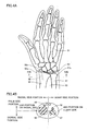
- FIGs. 4A and 4B a structure of a hand of a human body will be described and definition of terms used herein will be provided.
- radius 56 and ulna 57 are located in wrist 52, extending between hand 51 and forearm 53.
- Radius 56 and ulna 57 are located parallel to each other from the elbow to wrist 52, and end portions of both of the radius and the ulna are located in wrist 52.
- the respective end portions of radius 56 and ulna 57 have protrusions referred to as radial styloid process 56a and ulnar styloid process 57a respectively.
- a radial artery 58 is located between radius 56 and the skin on the palm side of wrist 52.
- Wrist joint anterior surface stripe 52a is located on an outer surface on the palm side of wrist 52.
- the palm side of wrist 52 is referred to as the palm side portion
- the dorsal side thereof is referred to as the dorsal side portion
- radial 56 side thereof is referred to as the radial side portion
- ulnar 57 side thereof is referred to as the ulnar side portion.
- a portion located on the body surface of the radial side portion is referred to as an end portion on the radial side
- a portion located on the body surface of the ulnar side portion is referred to as an end portion on the ulnar side.
- a shape of a mount surface of the holding portion should be varied in order to allow a posture for measurement closer to natural for the subject.
- the palm side portion of the wrist faces the body in a natural posture. Therefore, the inventor assumed that the wrist is preferably positioned in a manner inclined somewhat diagonally with respect to the body during measurement, instead of the palm side portion of the wrist facing upward, considering a posture for measurement closer to natural.
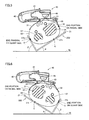
- Figs. 5 and 6 both show cross sections of the wrist viewed from a peripheral side toward a central side.
- wrist 52 when measurement is performed on the left wrist, wrist 52 is inclined toward the body, that is, in such a manner that the palm side thereof faces the body, so that the end portion on the radial side of wrist 52 is located above the end portion on the ulnar side of the same.
- wrist 52 is inclined such that the end portion on the radial side of wrist 52 is located above the end portion on the ulnar side of wrist 52, twisting of the brachium is mitigated and the subject can take a more natural posture.
- a holding portion 20D shown in Fig. 5 has support surface 21 receiving the dorsal side portion of wrist 52, and support surface 21 includes a first support region 27a receiving the radial side portion of wrist 52 and a second support region 27b receiving the ulnar side portion of wrist 52.
- support surface 21, first support region 27a, and second support region 27b are designed taking into account individual difference in a size of the wrist of the subject, and they refer to regions intended to support wrist 52 when the subject actually places his/her wrist 52 on holding portion 20D respectively.
- first support region 27a and second support region 27b both have planar shape, and come in contact with the radial side portion and the ulnar side portion of wrist 52 at points C and D respectively.
- the support surface in first support region 27a is inclined more gently than the support surface in second support region 27b. That is, when an angle ⁇ between a horizontal surface 70 and the support surface in first support region 27a is compared with an angle ⁇ between horizontal surface 70 and the support surface in second support region 27b, angle ⁇ is larger than angle ⁇ .
- first support region 27a extends above second support region 27b. That is, in order to receive a wrist having an oval cross sectional shape, first support region 27a is formed to have a length larger than second support region 27b. As a result, first support region 27a extends higher than second support region 27b.
- support surface 21 is formed asymmetrically around vertical centerline 91 including the central portion of support surface 21 in a cross section along a direction in which first support region 27a and second support region 27b are aligned (that is, shown cross section).
- support surface 21 is formed to have an asymmetrical shape so that the end portion on the radial side of left wrist 52 having an oval cross sectional shape is located above the end portion on the ulnar side thereof.
- holding portion 20D By structuring holding portion 20D in the above-described manner, when the left arm is placed in holding portion 20D, a wrist 52 position can be guided such that the end portion on the radial side of wrist 52 is located above the end portion on the ulnar side thereof. Therefore, a posture for measurement closer to natural for the subject can be allowed, and the pulse wave can be measured in a stable manner with high accuracy.
- radial artery 58 is located in the upper portion of placed wrist 52. Accordingly, positioning of sensor unit 40 is facilitated, and pressure-sensing portion 46 can readily be set right above radial artery 58.
- wrist 52 when measurement is performed on right wrist 52 as well, wrist 52 is inclined toward the body, that is, in such a manner that the palm side faces the body, so that the end portion on the radial side of wrist 52 is located above the end portion on the ulnar side of wrist 52. In this manner, when wrist 52 is inclined such that the end portion on the radial side of wrist 52 is located above the end portion on the ulnar side of wrist 52, twisting of the brachium is mitigated and the subject can take a more natural posture.
- FIG. 6 One exemplary shape of the holding portion allowing such a wrist position is as shown in Fig. 6.
- a holding portion 20E of a shape shown in Fig. 6 is structured symmetrically to holding portion 20A for the left arm described above. Since its structure and an effect therefrom are substantially the same as in holding portion 20D, description thereof will not be repeated.
- the pulse wave can be measured in a stable manner with high accuracy without causing pain to the subject.
- the structure of the holding portion of the wrist securing device for a pulse wave measuring apparatus allowing such a posture for measurement is not limited to the structure as those shown in Figs. 5 and 6.
- the wrist securing device for a pulse wave measuring apparatus allowing the above-described posture for measurement as well as the pulse wave measuring apparatus equipped with the same will be described.
- a pulse wave measuring apparatus 1A in a first embodiment mainly includes sensor unit 40, a wrist securing device 10A for a pulse wave measuring apparatus serving as a living body securing device, and fastening bands 31, 32.
- Sensor unit 40 is connected to wrist securing device 10A for a pulse wave measuring apparatus by fastening bands 31 and 32.
- the fastening band is implemented by first band portion 31 having one end attached to sensor unit 40 and the other end attached to wrist securing device 10A for a pulse wave measuring apparatus and by second band portion 32 having one end attached to sensor unit 40 and the other end detachably attached to wrist securing device 10A for a pulse wave measuring apparatus.
- each band is moderately flexible.
- sensor unit 40 and wrist securing device 10A for a pulse wave measuring apparatus are connected to each other by a signal cable 47 and an air tube 48.
- Wrist securing device 10A for a pulse wave measuring apparatus is placed on a flat base such as a desk during use.
- Wrist securing device 10A for a pulse wave measuring apparatus includes securing base main body 11 mounted on a mount surface 80 (see Fig. 9) and a holding portion 20A provided in an upper portion of securing base main body 11.
- a mount surface 80 see Fig. 9
- a holding portion 20A provided in an upper portion of securing base main body 11.
- an operation button or an output terminal is provided in front face 11 a of securing base main body 11.
- concave portion 12 capable of receiving an arm from wrist to elbow of the subject and a concave portion 11b to which holding portion 20A is fitted are provided.
- Concave portion 12 is structured to have a shape fitting to the arm from the wrist to the elbow of the subject, for example.
- a buffer material such as a cushion material made from sponge, for example, is adhered to the surface of concave portion 12.
- a structure solely having a buffer material adhered without a concave portion in the upper portion of securing base main body 11 may be adopted.
- Holding portion 20A is detachably attached to concave portion 11b provided in the upper portion of securing base main body 11. Fastening of holding portion 20A to securing base main body 11 is achieved by a hook and loop fastener 11d adhered to concave portion 11b of securing base main body 11 and a hook and loop fastener 25a adhered to a lower surface of a bottom portion 25 of holding portion 20A (see Fig. 9). In fastening holding portion 20A to securing base main body 11, an engagement protrusion 24 provided in holding portion 20A is fitted into an engagement recess 11c provided in the securing base main body, so as to achieve positioning.
- holding portion 20A has support surface 21 receiving the wrist in its upper portion.
- Support surface 21 is curved so as to fit to the wrist.
- Support surface 21 includes first support region 27a receiving the radial side portion of the wrist and second support region 27b receiving the ulnar side portion thereof.
- a concave portion 23a receiving the dorsal side portion corresponding to the ulnar styloid process of the left wrist when the left arm is placed on holding portion 20A is provided.
- a marker line 28 is provided in an up-down direction. An end of marker line 28 partially enters support surface 21, so that marker line 28 is visually recognized when holding portion 20A is viewed from above.
- engagement protrusion 24 fitted to securing base main body 11 described above is provided in a prescribed position of holding portion 20A.
- first support region 27a is structured to incline more gently than the support surface in second support region 27b.
- first support region 27a extends above second support region 27b.
- support surface 21 is formed asymmetrically around vertical centerline 91 including the central portion of support surface 21 in a cross section along a direction in which first support region 27a and second support region 27b are aligned (that is, shown cross section).
- sensor unit 40 includes casing body 41 having a pressure-sensing portion 46 (see Fig. 10) and base body 42 supporting casing body 41.
- Casing body 41 is structured such that it can slide on a rail provided in base body 42 in a longitudinal direction of fastening bands 31 and 32. In other words, casing body 41 freely slides between a position closing opening 43 provided in base body 42 (waiting position) and a position not closing the same (housed position).
- Fig. 7 shows casing body 41 in a housed position. When casing body 41 is slid, casing body 41 is moved with engagement release button 45 provided on a side surface of casing body 41 being pressed.
- Opening 43 is provided such that pressure-sensing portion 46 arranged inside casing body 41 can be pressed against the wrist on which measurement is performed.
- pressure-sensing portion 46 is lowered through opening 43, pressure-sensing portion 46 is pressed against the wrist so as to allow measurement of the pulse wave.
- display portion 44 for displaying whether or not pressure-sensing portion 46 is in an appropriate position during measurement is provided on the upper surface of sensor unit 40.
- first band portion 31 and second band portion 32 serving as the fastening bands are attached to prescribed positions in base body 42 respectively, with opening 43 of base body 42 of sensor unit 40 lying therebetween.
- a hook and loop fastener 32a (see Fig. 10) is adhered on an inner side of a tip end of the other end of second band portion 32.
- an opening 13a is provided in concave portion 11b provided in the upper portion of securing base main body 11.
- First band portion 31 is drawn out of opening 13a.
- an opening 13b is formed in a side surface of securing base main body 11, through which a portion of first band portion 31 is exposed in its non-attached state (a state in which the wrist is not secured by the living body securing device).
- a hook and loop fastener (not shown) is adhered to a prescribed region in the side surface adjacent to opening 13b of securing base main body 11.
- a hook and loop fastener 31a is adhered also to a surface of a portion exposed through opening 13b.
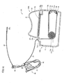
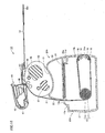
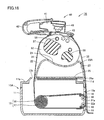
- a constant-load spring 15 serving as the pulling means is arranged inside securing base main body 11.
- the constant-load spring refers to a spring formed by winding a long-length leaf spring 17 bent with a constant curvature around a shaft 16, and restoring force produced when a tip end of leaf spring 17 is linearly pulled is constantly applied thereto regardless of a pulled length.
- First band portion 31 passing through opening 13a has the other end fixed and adhered to the tip end of leaf spring 17. Accordingly, while first band portion 31 is being pulled, the other end of first band portion 31 is constantly pulled by constant-load spring 15 with a constant pull strength.
- First band portion 31 is guided by a plurality of rollers 18 in securing base main body 11. Therefore, smooth pull-out and pull-in of first band portion 31 from securing base main body 11 is achieved.
- the arm from the elbow to the wrist is placed on concave portion 12 provided on the upper surface of securing base main body 11.
- wrist joint anterior surface stripe 52a located on the body surface on the palm side of the wrist is brought to a position corresponding to positioning marker line 28 provided on the side surface 22 of holding portion 20A.
- wrist 52 of the subject is held by holding portion 20A of securing base main body 11 in a stable manner, with the end portion on the radial side of wrist 52 being located above the end portion on the ulnar side thereof.
- first band portion 31 is pulled out from securing base main body 11 by a prescribed length, and sensor unit 40 is brought to a position right above wrist 52 of the subject.
- sensor unit 40 is positioned and arranged such that the center of opening 43 in base body 42 is located approximately above radial artery 58.
- first band portion 3 1 As the other end of first band portion 3 1 is fixed and adhered to one end of constant-load spring 15 arranged inside securing base main body 11, a constant pull strength produced by pulling out first band portion 31 from securing base main body 11 is applied to the other end of first band portion 31. Accordingly, when grasping of first band portion 31 is released, an excessive portion of first band portion 31 is pulled back into securing base main body 11 by constant-load spring 15, so that first band portion 31 fits to wrist 52 and securing base main body 11 without loosening.
- sensor unit 40 should lightly be held on wrist 52 so as to avoid displacement of sensor unit 40 that has been positioned and arranged in advance.
- second band portion 32 is attached on the side surface of securing base main body 11 on the side opposite to the side surface from which first band portion 31 is pulled out.
- a hook and loop fastener (not shown) adhered on the side surface of securing base main body 11 and hook and loop fastener 31 adhered to first band portion 31 as well as hook and loop fastener 32a adhered to the inner side of the tip end of the other end of second band portion 32 are used.
- casing body 41 of sensor unit 40 is slid as shown in Fig. 14, so as to be arranged at a position closing opening 43 in base body 42 (waiting position). Then, an air bag arranged above pressure-sensing portion 46 is expanded using a pressurization pump arranged in securing base main body 11 through air tube 48 (see Fig. 7), whereby pressure-sensing portion 46 is lowered through opening 43 toward wrist 52 and pressed against wrist 52. In this manner, the pulse wave is measured with pressure-sensing means provided in pressure-sensing portion 46.
- concave portion 23 a is provided in a position facing the dorsal side portion corresponding to the ulnar styloid process of the left wrist (see Fig. 8).
- concave portion 23a provided in holding portion 20A receives the dorsal side portion corresponding to the ulnar styloid process of the left wrist.
- holding portion 20A of wrist securing device 10A for a pulse wave measuring apparatus in the present embodiment is devised so as to receive also the right arm instead of the left arm.
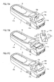
- a structure allowing reception of the right arm instead of the left arm will be described with reference to Figs. 16 and 17A-17C.
- holding portion 20A is formed symmetrically with respect to a longitudinal direction in the drawing around centerline 92.
- holding portion 20A includes a left wrist receiving region 29a receiving the left wrist and a right wrist receiving region 29b receiving the right wrist, that are respectively provided in positions axially symmetrical around centerline 92.
- support surface 21 of holding portion 20A includes a concave portion 23b receiving the dorsal side portion corresponding to the ulnar styloid process of the right wrist when the right arm is placed on holding portion 20A, in a position axially symmetrical to concave portion 23 a around centerline 92.
- holding portion 20A is attached to securing base main body 11 after it is turned by 180° in a plane parallel to the upper surface of securing base main body 11. In this manner, a first state allowing the use of left wrist receiving region 29a and a second state allowing the use of right wrist receiving region 29b are switched.
- holding portion 20A is removed from securing base main body 11, and turned in a direction shown with an arrow E as shown in Fig. 17B.
- holding portion 20A is attached to securing base main body 11 as shown in Fig. 17C, so as to achieve the second state allowing the use of right wrist receiving region 29b.
- wrist securing device 10A for a pulse wave measuring apparatus in the present embodiment can be switched between the use for the right arm and the use for the left arm with a very simple operation, thereby attaining excellent usability.
- wrist 52 position is guided such that the end portion on the radial side of wrist 52 is located above the end portion on the ulnar side thereof even while pulse wave measuring apparatus 1A is attached to the right arm of the subject. Therefore, a posture for measurement closer to natural for the subject can be achieved, thereby allowing measurement of the pulse wave in a stable manner with high accuracy.
- a holding portion 20B of a wrist securing device 10B for a pulse wave measuring apparatus in a second embodiment is different from holding portion 20A of wrist securing device 10A for a pulse wave measuring apparatus in the first embodiment described above in a structure of support surface 21 receiving the dorsal side portion corresponding to the ulnar styloid process of wrist 52.
- pulse wave measuring apparatus 1B has a structure otherwise the same as pulse wave measuring apparatus 1A in the first embodiment described above, the same reference characters denote the same or corresponding components and description thereof will not repeated.
- buffer material 26 is located in a position facing the dorsal side portion corresponding to the ulnar styloid process of the wrist.
- a sponge-like cushion material formed with synthetic fibers or a rubber material may be employed as buffer material 26.
- a holding portion 20C of a wrist securing device 10C for a pulse wave measuring apparatus in a third embodiment is different from holding portion 20A of wrist securing device 10A for a pulse wave measuring apparatus in the first embodiment described above in a structure for attachment to the securing base main body.
- pulse wave measuring apparatus 1 C has a structure otherwise the same as pulse wave measuring apparatus 1A in the first embodiment described above, the same reference characters denote the same or corresponding components and description thereof will not repeated.
- holding portion 20C is attached to an upper portion of securing base main body 11 in a swingable manner by means of a swing shaft 62, instead of being attached to securing base main body 11 in a detachable manner.
- swing of holding portion 20C is restricted to be within a certain range by abutment of the lower surface of holding portion 20C on the bottom surface of a concave portion 11e provided in the upper portion of securing base main body 11.
- Holding portion 20C includes a first base portion 61a and a second base portion 61b extending in different directions from swing shaft 62.
- a pivot member 63a is pivotably attached to an end portion of first base portion 61a
- a pivot member 63b is pivotably attached to an end portion of second base portion 61b.
- concave portion 23a receiving the dorsal side portion corresponding to the ulnar styloid process of the left wrist is provided in a prescribed position in first base portion 6 1a
- concave portion 23b receiving the dorsal side portion corresponding to the ulnar styloid process of the right wrist is provided in a prescribed position in second base portion 61b.
- Fig. 20A shows a first state in which the left wrist rests on holding portion 20C.
- the lower surface of first base portion 61a of holding portion 20C abuts on the bottom surface of concave portion 11e provided in securing base main body 11, and swing of holding portion 20C is restricted by a not-shown stopper.
- Support surface 21 including left wrist receiving region 29a receiving left wrist 52 is implemented by the upper surface of first base portion 61a and the upper surface of pivot member 63a.
- Support surface 21 has first support region 27a receiving the radial side portion of wrist 52 and second support region 27b receiving the ulnar side portion of wrist 52.
- Support surface 21 has a shape receiving wrist 52 in an inclined position such that the end portion on the radial side of wrist 52 is located above the end portion on the ulnar side thereof.
- Fig. 20B shows a second state in which the right wrist rests on holding portion 20C.
- the lower surface of second base portion 61b of holding portion 20C abuts on the bottom surface of concave portion 11e provided in securing base main body 11, and swing of holding portion 20C is restricted by a not-shown stopper.
- Support surface 21 including right wrist receiving region 29b receiving right wrist 52 is implemented by the upper surface of second base portion 61b and the upper surface of pivot member 63b.
- Support surface 21 has first support region 27a receiving the radial side portion of wrist 52 and second support region 27b receiving the ulnar side portion of wrist 52.
- Support surface 21 has a shape receiving wrist 52 in an inclined position such that the end portion on the radial side of wrist 52 is located above the end portion on the ulnar side thereof.
- the first state shown in Fig. 20A and the second state shown in Fig. 20B are switched by an operation of the not-shown stopper and swing of holding portion 20C in a direction shown with arrow F around swing shaft 62.
- the first state allowing the use of left wrist receiving region 29a and the second state allowing the use of right wrist receiving region 29b are switched.
- the wrist securing device for a pulse wave measuring apparatus can be switched between the use for the right arm and the use for the left arm with a very simple operation, thereby attaining excellent usability.
Landscapes
- Health & Medical Sciences (AREA)
- Life Sciences & Earth Sciences (AREA)
- Cardiology (AREA)
- Engineering & Computer Science (AREA)
- Heart & Thoracic Surgery (AREA)
- Physiology (AREA)
- Biophysics (AREA)
- Pathology (AREA)
- Vascular Medicine (AREA)
- Biomedical Technology (AREA)
- Physics & Mathematics (AREA)
- Medical Informatics (AREA)
- Molecular Biology (AREA)
- Surgery (AREA)
- Animal Behavior & Ethology (AREA)
- General Health & Medical Sciences (AREA)
- Public Health (AREA)
- Veterinary Medicine (AREA)
- Measuring Pulse, Heart Rate, Blood Pressure Or Blood Flow (AREA)
Applications Claiming Priority (2)
| Application Number | Priority Date | Filing Date | Title |
|---|---|---|---|
| JP2003324917A JP4306381B2 (ja) | 2003-09-17 | 2003-09-17 | 脈波測定装置用手首固定具および脈波測定装置 |
| JP2003324917 | 2003-09-17 |
Publications (1)
| Publication Number | Publication Date |
|---|---|
| EP1516580A1 true EP1516580A1 (de) | 2005-03-23 |
Family
ID=34191321
Family Applications (1)
| Application Number | Title | Priority Date | Filing Date |
|---|---|---|---|
| EP04021910A Withdrawn EP1516580A1 (de) | 2003-09-17 | 2004-09-14 | Handgelenk-Haltevorrichtung für Pulswellenmessgerät |
Country Status (4)
| Country | Link |
|---|---|
| US (1) | US20050065442A1 (de) |
| EP (1) | EP1516580A1 (de) |
| JP (1) | JP4306381B2 (de) |
| CN (1) | CN1596824A (de) |
Cited By (1)
| Publication number | Priority date | Publication date | Assignee | Title |
|---|---|---|---|---|
| DE112010003588B4 (de) | 2009-09-08 | 2018-07-19 | Korea Institute Of Industrial Technology | Vorrichtung zum Messen von biometrischen Informationen |
Families Citing this family (31)
| Publication number | Priority date | Publication date | Assignee | Title |
|---|---|---|---|---|
| CN100450433C (zh) * | 2005-11-15 | 2009-01-14 | 北京中医药大学 | 一种脉象检测装置 |
| JP4626593B2 (ja) * | 2006-09-07 | 2011-02-09 | オムロンヘルスケア株式会社 | 脈波測定装置用手首保持台およびこれを備えた脈波測定装置 |
| JP4820961B2 (ja) * | 2008-05-16 | 2011-11-24 | 株式会社最新松本技研 | 脈拍異常検出装置 |
| KR101073929B1 (ko) * | 2009-09-08 | 2011-10-17 | 한국생산기술연구원 | 맥파측정장치 |
| KR101029784B1 (ko) | 2009-09-08 | 2011-04-19 | 한국생산기술연구원 | 손 거치대가 구비된 생체정보 측정장치 |
| DE112010003582T5 (de) | 2009-09-08 | 2012-08-16 | Korea Institute Of Industrial Technology | Vorrichtung zum Messen von biometrischen Informationen mit einer Handablage |
| CN102018501A (zh) * | 2009-09-21 | 2011-04-20 | 上海道生医疗科技有限公司 | 脉诊仪 |
| JP2012139286A (ja) * | 2010-12-28 | 2012-07-26 | Omron Healthcare Co Ltd | 血圧測定装置 |
| CN103565428B (zh) * | 2012-07-18 | 2015-12-09 | 株式会社日立制作所 | 脉搏检测装置及脉搏检测方法 |
| JP6129626B2 (ja) * | 2013-04-12 | 2017-05-17 | 古野電気株式会社 | 超音波骨診断装置 |
| CN103300835B (zh) * | 2013-05-28 | 2015-06-24 | 北京航空航天大学 | 一种高精度人体脉动测量系统 |
| CN104287709B (zh) * | 2014-09-11 | 2017-03-29 | 西安力邦医疗电子有限公司 | 血压测量定位装置 |
| JP6287894B2 (ja) * | 2015-02-27 | 2018-03-07 | オムロンヘルスケア株式会社 | 血圧測定用カフおよび血圧計 |
| JP6480769B2 (ja) * | 2015-03-18 | 2019-03-13 | キヤノン株式会社 | 撮影装置、撮影システム及び撮影装置で用いられる支持部材 |
| EP3269299B1 (de) * | 2015-04-08 | 2019-05-22 | Nipro Corporation | Blutdruckmesser |
| JP6597083B2 (ja) * | 2015-09-07 | 2019-10-30 | オムロンヘルスケア株式会社 | 脈波検出装置 |
| JP2017051276A (ja) * | 2015-09-07 | 2017-03-16 | オムロンヘルスケア株式会社 | 脈波検出装置 |
| JP2017070630A (ja) * | 2015-10-09 | 2017-04-13 | 株式会社デンソー | 血圧測定装置 |
| JP6682971B2 (ja) * | 2016-04-13 | 2020-04-15 | オムロンヘルスケア株式会社 | 脈波検出装置及び生体情報測定装置 |
| CN106913319B (zh) * | 2017-03-23 | 2020-04-24 | 武汉大学 | 一种仿生按压的三段式定位脉象检测装置及方法 |
| CN107440700B (zh) * | 2017-07-03 | 2023-08-01 | 浙江善时生物药械(商丘)有限公司 | 一种用于手腕连续血压测量器的稳压保护装置 |
| CN108309351B (zh) * | 2018-03-07 | 2024-06-04 | 北京悦琦创通科技有限公司 | 骨密度测量部位标记装置 |
| JP2019201986A (ja) * | 2018-05-24 | 2019-11-28 | オムロンヘルスケア株式会社 | 血圧測定装置 |
| JP2019201984A (ja) * | 2018-05-24 | 2019-11-28 | オムロンヘルスケア株式会社 | 血圧測定装置 |
| CN108937879A (zh) * | 2018-06-14 | 2018-12-07 | 博脉有限公司 | 一种诊脉仪及诊脉设备 |
| USD925041S1 (en) * | 2018-11-20 | 2021-07-13 | Amorv (Ip) Company Limited | Wrist electronic device |
| CN109481035B (zh) * | 2018-12-19 | 2024-11-29 | 智美康民(珠海)健康科技有限公司 | 用于脉诊仪的手腕固定装置 |
| JP2020120794A (ja) * | 2019-01-29 | 2020-08-13 | 京セラ株式会社 | 電子機器 |
| CN111904398A (zh) * | 2020-09-01 | 2020-11-10 | 长沙开山斧智能科技有限公司 | 一种桡动脉检测装置及其检测方法 |
| CN114668374B (zh) * | 2022-03-29 | 2024-08-13 | 青岛市中医医院(青岛市海慈医院、青岛市康复医学研究所) | 基于束缚腕部的护理呼吸科脉搏测量装置 |
| CN115137320A (zh) * | 2022-07-02 | 2022-10-04 | 北京天益佳科技有限公司 | 一种定位寸关尺位置的方法和将所获取信息输出的方法 |
Citations (4)
| Publication number | Priority date | Publication date | Assignee | Title |
|---|---|---|---|---|
| JPH1133007A (ja) * | 1997-07-14 | 1999-02-09 | Nippon Colin Co Ltd | 圧脈波検出用手首固定装置 |
| EP1177762A1 (de) * | 1999-04-21 | 2002-02-06 | Jie Kan | Vorrichtung und verfahren zur nichtinvasiven blutdruckmessung |
| EP1360930A1 (de) * | 2002-05-09 | 2003-11-12 | Omron Corporation | Pulswellenmonitor |
| EP1440658A1 (de) * | 2003-01-24 | 2004-07-28 | Omron Healthcare Co., Ltd. | Pulswellen Messgerät |
Family Cites Families (13)
| Publication number | Priority date | Publication date | Assignee | Title |
|---|---|---|---|---|
| US4993422A (en) * | 1986-05-02 | 1991-02-19 | The Hon Group | Apparatus for measuring blood pressure |
| JPH0428562Y2 (de) * | 1988-02-23 | 1992-07-10 | ||
| US5240007A (en) * | 1991-05-14 | 1993-08-31 | Ivac Corporation | Apparatus and method for moving a tissue stress sensor for applanating an artery |
| US5271405A (en) * | 1991-05-14 | 1993-12-21 | Boyer Stanley J | Wrist mount apparatus for use in blood pressure tonometry |
| JPH0511906U (ja) * | 1991-07-29 | 1993-02-19 | コーリン電子株式会社 | 圧脈波検出用センサの装着用シート |
| US5617867A (en) * | 1994-11-23 | 1997-04-08 | Ivac Medical Systems, Inc. | Tonometer mounting device |
| DE69829152T2 (de) * | 1997-03-25 | 2006-05-11 | Seiko Epson Corp. | Vorrichtung zur Messung von Pulswellen |
| US6558335B1 (en) * | 2000-11-22 | 2003-05-06 | Medwave, Inc | Wrist-mounted blood pressure measurement device |
| JP4363157B2 (ja) * | 2002-11-29 | 2009-11-11 | オムロンヘルスケア株式会社 | 脈波測定装置 |
| JP3858824B2 (ja) * | 2003-01-10 | 2006-12-20 | オムロンヘルスケア株式会社 | 脈波測定装置 |
| JP4306382B2 (ja) * | 2003-01-23 | 2009-07-29 | オムロンヘルスケア株式会社 | 脈波測定装置 |
| JP4166665B2 (ja) * | 2003-10-24 | 2008-10-15 | 日本精密測器株式会社 | 手首用血圧計及びカフスプリング |
| US20060111637A1 (en) * | 2004-11-23 | 2006-05-25 | Jacober Jeffrey M | Wrist-mount blood pressure monitor with auditory feature |
-
2003
- 2003-09-17 JP JP2003324917A patent/JP4306381B2/ja not_active Expired - Lifetime
-
2004
- 2004-09-14 EP EP04021910A patent/EP1516580A1/de not_active Withdrawn
- 2004-09-16 US US10/942,082 patent/US20050065442A1/en not_active Abandoned
- 2004-09-17 CN CNA2004100797123A patent/CN1596824A/zh active Pending
Patent Citations (4)
| Publication number | Priority date | Publication date | Assignee | Title |
|---|---|---|---|---|
| JPH1133007A (ja) * | 1997-07-14 | 1999-02-09 | Nippon Colin Co Ltd | 圧脈波検出用手首固定装置 |
| EP1177762A1 (de) * | 1999-04-21 | 2002-02-06 | Jie Kan | Vorrichtung und verfahren zur nichtinvasiven blutdruckmessung |
| EP1360930A1 (de) * | 2002-05-09 | 2003-11-12 | Omron Corporation | Pulswellenmonitor |
| EP1440658A1 (de) * | 2003-01-24 | 2004-07-28 | Omron Healthcare Co., Ltd. | Pulswellen Messgerät |
Non-Patent Citations (1)
| Title |
|---|
| PATENT ABSTRACTS OF JAPAN vol. 1999, no. 05 31 May 1999 (1999-05-31) * |
Cited By (1)
| Publication number | Priority date | Publication date | Assignee | Title |
|---|---|---|---|---|
| DE112010003588B4 (de) | 2009-09-08 | 2018-07-19 | Korea Institute Of Industrial Technology | Vorrichtung zum Messen von biometrischen Informationen |
Also Published As
| Publication number | Publication date |
|---|---|
| CN1596824A (zh) | 2005-03-23 |
| JP4306381B2 (ja) | 2009-07-29 |
| US20050065442A1 (en) | 2005-03-24 |
| JP2005087483A (ja) | 2005-04-07 |
Similar Documents
| Publication | Publication Date | Title |
|---|---|---|
| EP1516580A1 (de) | Handgelenk-Haltevorrichtung für Pulswellenmessgerät | |
| US5511546A (en) | Finger apparatus for measuring continuous cutaneous blood pressure and electrocardiogram electrode | |
| US20100168531A1 (en) | Rapidly deployable sensor design for enhanced noninvasive vital sign monitoring | |
| JP4441132B2 (ja) | 血圧モニタリング方法および装置 | |
| US7359742B2 (en) | Sensor assembly | |
| US7374540B2 (en) | Non-invasive probe for detecting medical conditions | |
| US6516289B2 (en) | Physiological measuring system comprising a garment and sensing apparatus incorporated in the garment | |
| US4993422A (en) | Apparatus for measuring blood pressure | |
| TWI301755B (en) | Blood pressure measuring apparatus | |
| JPH0668727U (ja) | パルスオキシメータ用プローブ | |
| JPWO1998042254A1 (ja) | 脈波検出装置、拍動検出装置および圧力検出装置 | |
| JP2003510120A (ja) | フィンガーホルダを用いて血液に関する信号の非侵襲的測定を行なうための光学的装置 | |
| JPH04227241A (ja) | トランスデューサヘッド | |
| KR102320959B1 (ko) | 손가락형 산소포화도 측정기용 가드 | |
| WO2010073913A1 (ja) | 生体情報測定用プローブ | |
| US8463367B2 (en) | Apparatus for measuring biological information and earphone having the same | |
| CA1298990C (en) | Apparatus for measuring blood pressure | |
| WO2024184896A1 (en) | Optical digit probe for noninvasive measurement of physiological parameters | |
| JP5209889B2 (ja) | 医用測定器具および生体情報測定装置 | |
| TWI566743B (zh) | Fiber type continuous detection of blood pressure sensor and wear device | |
| TWI228408B (en) | Method and device for monitoring blood pressure | |
| CN215017470U (zh) | 一种用于加固指夹式血氧仪的防挣脱手套 | |
| JP2775048B2 (ja) | 聴診器保持具及びその使用方法 | |
| JP3835450B2 (ja) | 脈波検出装置および拍動検出装置 | |
| EP4601543B1 (de) | System und verfahren zur positionierung eines sensorpatches auf einem benutzer |
Legal Events
| Date | Code | Title | Description |
|---|---|---|---|
| PUAI | Public reference made under article 153(3) epc to a published international application that has entered the european phase |
Free format text: ORIGINAL CODE: 0009012 |
|
| AK | Designated contracting states |
Kind code of ref document: A1 Designated state(s): AT BE BG CH CY CZ DE DK EE ES FI FR GB GR HU IE IT LI LU MC NL PL PT RO SE SI SK TR |
|
| AX | Request for extension of the european patent |
Extension state: AL HR LT LV MK |
|
| RIN1 | Information on inventor provided before grant (corrected) |
Inventor name: ITONAGA, KAZUNOBU C/O OMRON HEALTHCARE CO. LTD. Inventor name: HASHIMOTO, MASAO C/O OMRON HEALTHCARE CO. LTD. |
|
| 17P | Request for examination filed |
Effective date: 20050826 |
|
| AKX | Designation fees paid |
Designated state(s): DE ES FR GB IT |
|
| STAA | Information on the status of an ep patent application or granted ep patent |
Free format text: STATUS: THE APPLICATION HAS BEEN WITHDRAWN |
|
| 18W | Application withdrawn |
Effective date: 20090715 |