EP1515872B1 - Haltevorrichtung für ein telefon - Google Patents
Haltevorrichtung für ein telefon Download PDFInfo
- Publication number
- EP1515872B1 EP1515872B1 EP03740252A EP03740252A EP1515872B1 EP 1515872 B1 EP1515872 B1 EP 1515872B1 EP 03740252 A EP03740252 A EP 03740252A EP 03740252 A EP03740252 A EP 03740252A EP 1515872 B1 EP1515872 B1 EP 1515872B1
- Authority
- EP
- European Patent Office
- Prior art keywords
- drive unit
- telephone
- drive
- holding device
- cover
- Prior art date
- Legal status (The legal status is an assumption and is not a legal conclusion. Google has not performed a legal analysis and makes no representation as to the accuracy of the status listed.)
- Expired - Lifetime
Links
- 238000007599 discharging Methods 0.000 claims 1
- 238000000034 method Methods 0.000 description 7
- 238000004146 energy storage Methods 0.000 description 3
- 238000013016 damping Methods 0.000 description 2
- 238000012544 monitoring process Methods 0.000 description 2
- 239000004744 fabric Substances 0.000 description 1
- 238000009434 installation Methods 0.000 description 1
- 239000010985 leather Substances 0.000 description 1
- 238000003825 pressing Methods 0.000 description 1
Images


Classifications
-
- B—PERFORMING OPERATIONS; TRANSPORTING
- B60—VEHICLES IN GENERAL
- B60R—VEHICLES, VEHICLE FITTINGS, OR VEHICLE PARTS, NOT OTHERWISE PROVIDED FOR
- B60R11/00—Arrangements for holding or mounting articles, not otherwise provided for
- B60R11/02—Arrangements for holding or mounting articles, not otherwise provided for for radio sets, television sets, telephones, or the like; Arrangement of controls thereof
- B60R11/0241—Arrangements for holding or mounting articles, not otherwise provided for for radio sets, television sets, telephones, or the like; Arrangement of controls thereof for telephones
-
- B—PERFORMING OPERATIONS; TRANSPORTING
- B60—VEHICLES IN GENERAL
- B60R—VEHICLES, VEHICLE FITTINGS, OR VEHICLE PARTS, NOT OTHERWISE PROVIDED FOR
- B60R11/00—Arrangements for holding or mounting articles, not otherwise provided for
- B60R2011/0001—Arrangements for holding or mounting articles, not otherwise provided for characterised by position
- B60R2011/0003—Arrangements for holding or mounting articles, not otherwise provided for characterised by position inside the vehicle
- B60R2011/0005—Dashboard
-
- B—PERFORMING OPERATIONS; TRANSPORTING
- B60—VEHICLES IN GENERAL
- B60R—VEHICLES, VEHICLE FITTINGS, OR VEHICLE PARTS, NOT OTHERWISE PROVIDED FOR
- B60R11/00—Arrangements for holding or mounting articles, not otherwise provided for
- B60R2011/0001—Arrangements for holding or mounting articles, not otherwise provided for characterised by position
- B60R2011/0003—Arrangements for holding or mounting articles, not otherwise provided for characterised by position inside the vehicle
- B60R2011/0007—Mid-console
-
- B—PERFORMING OPERATIONS; TRANSPORTING
- B60—VEHICLES IN GENERAL
- B60R—VEHICLES, VEHICLE FITTINGS, OR VEHICLE PARTS, NOT OTHERWISE PROVIDED FOR
- B60R11/00—Arrangements for holding or mounting articles, not otherwise provided for
- B60R2011/0042—Arrangements for holding or mounting articles, not otherwise provided for characterised by mounting means
- B60R2011/008—Adjustable or movable supports
- B60R2011/0085—Adjustable or movable supports with adjustment by rotation in their operational position
- B60R2011/0087—Adjustable or movable supports with adjustment by rotation in their operational position around two axes
-
- B—PERFORMING OPERATIONS; TRANSPORTING
- B60—VEHICLES IN GENERAL
- B60R—VEHICLES, VEHICLE FITTINGS, OR VEHICLE PARTS, NOT OTHERWISE PROVIDED FOR
- B60R11/00—Arrangements for holding or mounting articles, not otherwise provided for
- B60R2011/0042—Arrangements for holding or mounting articles, not otherwise provided for characterised by mounting means
- B60R2011/008—Adjustable or movable supports
- B60R2011/0092—Adjustable or movable supports with motorization
-
- B—PERFORMING OPERATIONS; TRANSPORTING
- B60—VEHICLES IN GENERAL
- B60R—VEHICLES, VEHICLE FITTINGS, OR VEHICLE PARTS, NOT OTHERWISE PROVIDED FOR
- B60R11/00—Arrangements for holding or mounting articles, not otherwise provided for
- B60R2011/0094—Arrangements for holding or mounting articles, not otherwise provided for characterised by means for covering after user, e.g. boxes, shutters or the like
Definitions
- the invention relates to a holding device for a telephone according to the preamble of claim 1, see DE 100 32 657 A.
- From DE 197 55 621 A1 discloses a receiving device for a Mobile phone known. There the mobile phone is on one Carriage slidably mounted. This one is from an electric motor driven, the sled into a shaft and out of the shaft.
- the disadvantage here is that the phone in the carriage ergonomically disadvantageous and thus is poorly usable.
- DE 198 17 345 A1 shows a vehicle console with a manual swivel phone holder.
- the phone is in recording position covered by a two-part cover.
- the disadvantage here is that the operation of this console little is comfortable because the cover and the phone for pivoting must be operated separately.
- the object of the present invention is a holding device to create a phone that is as comfortable as possible is operable, the phone protects while maintaining high reliability having.
- the holding device the phone have a high value appearance and aesthetic be designed attractively.
- the holding device has a drive device with two separately trained drives on.
- the first drive is driving a holding arm supporting the telephone
- the second drive drives a lid that picks up the phone Storage compartment closes.
- the phone is in the stowage position safely stowed in the storage compartment and against theft and / or pollution protected.
- the lid closes this Storage compartment safe and can be aesthetically pleasing on its outside be designed, for. B. a leather and / or Fabric cover and / or have a wooden surface.
- By the two Drives can be powered automatically by the phone Stowed position in the use position and driven back be, so that results in a comfortable operation. moreover has the drive device through the two separately formed Drives redundancy and thus operational safety.
- the drive device is a control device having to control the first and the second drive is formed.
- About the control device Can the movement when moving the phone from the stowed position to the use position and back to be controlled.
- the operability of the holding device can be simplified, z. B. may be provided a one-button operation. The means that in the stowage and in the use position one button or button press is enough to drive the device to control the phone.
- the separate drives each have different drive principles. This increases the reliability of the system. So can the first drive as an electric drive and the second drive designed as a mechanical drive with energy storage be. In a direction of movement, z. B. in the process from stowage to use position or back the electric drive charge the energy storage.
- the mechanical energy storage is a method of Phone and / or the lid even in case of power failure possible. Since the phone has its own power supply, can be reached in case of an emergency availability the phone may be required. A drive can be self-locking be formed, so even in case of power failure moving the phone or the lid through the second Drive or manually possible.
- the drive device a locking device for locking the lid having.
- the phone in stowed position the phone can be safe and protected against theft.
- the holding arm mechanical Recordings and electrical connections for the phone having. So is a simple electrical connection of the phone z. B. to a speakerphone possible. Also one Stable mechanical support on the support arm can by the Mounts can be achieved.
- the phone can work as a fixed phone or as a mobile phone, z. B. GSM phone or portable phone be. It is also possible instead of the phone or additionally a display or a handheld PC or a Keyboard to be attached to the support arm.
- the holding device can be advantageous in vehicles, preferably be used in passenger cars. There is one Installation of the holding device in the cockpit area or in the Center console provided.
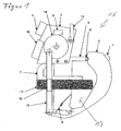
- FIG. 1 shows a holding device 16. It comprises a holding arm 1, on which a telephone 11 is mounted, a cover 2, a drive device 3 with spring motor, spring 9 and electric motor 10, a mounting frame 4 and a control device 5.
- the control device 5 has sensors 6.
- the arm 1 is shown with the phone in stowed position.
- the phone 11 is received in a storage compartment 17 which is closed by the lid 2.
- the lid 2 is held by a locking device 8 with rotary latch lock in this closed position.
- a mechanical drive with spring 9 and damper is connected to the cover 2 and acts on the cover 2 in the opening direction.
- the damper is designed as a viscous brake and dampens the opening movement of the lid 2.
- a arranged on the outside of the lid 2 switch 7 is actuated.
- the switch 7 is connected to the locking device 8 and the control device 5. He unlocks the locking device 8 whereupon the lid is acted upon by the spring 9 and its weight distribution in the opening direction.
- the mechanical drive is decoupled from the electric drive.
- control device 5 Via the sensors 6, the control device 5 recognizes the open position of the lid 2 shown in FIG . 2 and controls the electric motor 10 for extending the holding arm 1. After reaching the use position, which is shown in Figure 3, the control device 5 switches off the electric motor 10.
- the phone 11 from the arm 1 are taken. Similarly, while driving a passenger car the phone 11 via a speakerphone to be used.
- the control device 5 monitors by means of the sensors 6 the extension movement of the phone 11 z. B. by monitoring the take-up current of the electric motor 10. Will the extension movement impeded, z. B. by pinching, reverses the Control device 5 the drive 10 by a few millimeters and then switch off. After completion of the obstacle can by renewed actuation of the button 7 of the extension process continues become.
- the closing process is initiated by pressing the button 7.
- the control device is designed such that over the lever 12 and the connecting rod 13 while the lid 2 initially is maximally opened by the electric motor 10. Contemporaneous the electric motor 10 drives the holding arm 1 in the direction Stowed. The lid 2 remains open as long Position until the arm 1 is retracted as far as possible. Thereafter, the electric motor 10 acts on the cover 2 in the closing direction and charges the spring accumulator 9.
- the electric motor 10 acts on the eccentric disc 14 on the rotary latch lock 8 and locked this.
- the sensor 6 detects the end point of this movement, reports this to the control device 5, which then the drive 10 turns off. Also during the closing process is from the Control device 5 by monitoring the power consumption of Drive motor 10 monitors a possible pinching.
Landscapes
- Engineering & Computer Science (AREA)
- Mechanical Engineering (AREA)
- Fittings On The Vehicle Exterior For Carrying Loads, And Devices For Holding Or Mounting Articles (AREA)
- Telephone Set Structure (AREA)
Description
- Fig. 1
- Eine Haltevorrichtung mit einem Telefon in Verstauposition und einem geschlossenen Deckel,
- Fig. 2
- Die Haltevorrichtung mit geöffnetem Deckel,
- Fig. 3
- Die Haltevorrichtung mit Telefon in Gebrauchsposition und geöffnetem Deckel.
Claims (9)
- Haltevorrichtung für ein Telefon,
mit einer Antriebsvorrichtung (3), die das Telefon (11) zwischen einer in einem Staufach angeordneten Verstauposition und einer Gebrauchsposition verfährt, wobei die Antriebsvorrichtung (3) zwei separate Antriebe aufweist, wobei der erste Antrieb (10) als elektrischer Antrieb ausgebildet ist, der einen das Telefon (11) halternden Haltearm (1) und der zweite Antrieb (9) als mechanischer Antrieb mit einem Energiespeicher ausgebildet ist, der einen das Staufach (17) verschließenden Deckel (2) antreibt,
dadurch gekennzeichnet, dass der erste Antrieb (10) mit dem zweiten Antrieb (9) so gekoppelt ist, dass beim Verfahren des Telefons (11) von der Verstauposition in die Gebrauchsposition zuerst der zweite Antrieb (9) unter Entladung des Energiespeichers den Deckel (2) öffnet und nachdem der Deckel weitgehend geöffnet ist, der erste Antrieb (10) den Haltearm (1) zum Verbringen des Telefons (11) von der verstauposition in die Gebrauchsposition antreibt. - Haltevorrichtung nach Anspruch 1,
dadurch gekennzeichnet, dass die Antriebsvorrichtung (3) eine Steuervorrichtung (5) aufweist, die zum Steuern des ersten Antriebs (10) und des zweiten Antriebes (9) ausgebildet ist. - Haltevorrichtung nach Anspruch 1 oder 2,
dadurch gekennzeichnet, dass der erste Antrieb (10) einen Elektromotor und der zweite Antrieb (9) einen Federmotor aufweist. - Haltevorrichtung nach Anspruch 1 oder 3,
dadurch gekennzeichnet, dass der erste Antrieb (10) mit dem zweiten Antrieb (9) so gekoppelt ist, dass beim Verfahren des Telefons (11) von der Gebrauchsposition in die Verstauposition der erste Antrieb (10) den Haltearm (1) zum Verbringen des Telefons (11) von der Gebrauchsposition in die Verstauposition antreibt und dass nachdem die Verstauposition erreicht ist der erste Antrieb den Deckel (2) schließt und dabei den Energiespeicher des zweiten Antriebs lädt. - Haltevorrichtung nach einem der Ansprüche 1 bis 4,
dadurch gekennzeichnet, dass die Steuervorrichtung (6) einen elektrischen Bedientaster (7) aufweist, der bei manueller Betätigung ein signal zum Verfahren des Telefons (11) in Verstauposition und/oder in Gebrauchsposition generiert. - Haltevorrichtung nach einem der Ansprüche 1 bis 5,
dadurch gekennzeichnet, dass die Antriebsvorrichtung (3) eine Verriegelungsvorrichtung (8) zum Verriegeln des Deckels (2) in Verstauposition aufweist. - Haltevorrichtung nach einem der Ansprüche 1 bis 6,
dadurch gekennzeichnet, dass der erste Antrieb (10) selbsthemmungsfrei ausgebildet ist, so dass auch bei Ausfall des ersten Antriebs (10) der zweite Antrieb (9) den Deckel (2) öffnet. - Haltevorrichtung nach einem der Ansprüche 1 bis 7,
dadurch gekennzeichnet, dass die Steuervorrichtung (6) einen oder mehrere Sensoren (5) aufweist, die zum Erkennen von Positionen des Haltearmes und/oder des Deckels und/oder von Überlast eines Antriebs (10, 9) ausgebildet ist bzw. sind. - Haltevorrichtung nach einem der Ansprüche 1 bis 8,
dadurch gekennzeichnet, dass der Haltearm (1) eine elektrische Steckverbindung aufweist, die zum elektrischen Anschluss des Telefons (11) ausgebildet ist.
Applications Claiming Priority (3)
| Application Number | Priority Date | Filing Date | Title |
|---|---|---|---|
| DE2002127922 DE10227922A1 (de) | 2002-06-21 | 2002-06-21 | Haltevorrichtung für ein Telefon |
| DE10227922 | 2002-06-21 | ||
| PCT/EP2003/006301 WO2004000608A1 (de) | 2002-06-21 | 2003-06-14 | Haltevorrichtung für ein telefon |
Publications (2)
| Publication Number | Publication Date |
|---|---|
| EP1515872A1 EP1515872A1 (de) | 2005-03-23 |
| EP1515872B1 true EP1515872B1 (de) | 2005-11-09 |
Family
ID=29719372
Family Applications (1)
| Application Number | Title | Priority Date | Filing Date |
|---|---|---|---|
| EP03740252A Expired - Lifetime EP1515872B1 (de) | 2002-06-21 | 2003-06-14 | Haltevorrichtung für ein telefon |
Country Status (4)
| Country | Link |
|---|---|
| EP (1) | EP1515872B1 (de) |
| JP (1) | JP2005534550A (de) |
| DE (2) | DE10227922A1 (de) |
| WO (1) | WO2004000608A1 (de) |
Families Citing this family (3)
| Publication number | Priority date | Publication date | Assignee | Title |
|---|---|---|---|---|
| US20070155738A1 (en) | 2005-05-20 | 2007-07-05 | Alantos Pharmaceuticals, Inc. | Heterobicyclic metalloprotease inhibitors |
| DE102007032667B4 (de) | 2007-07-13 | 2009-07-23 | Beqasirius Ag | Freisprecheinrichtung |
| JP5797064B2 (ja) * | 2011-08-26 | 2015-10-21 | アルパイン株式会社 | 表示装置 |
Family Cites Families (3)
| Publication number | Priority date | Publication date | Assignee | Title |
|---|---|---|---|---|
| DE19817345B4 (de) * | 1998-04-18 | 2007-12-27 | Volkswagen Ag | Fahrzeugkonsole mit einer verschwenkbaren Halterung für ein Autotelefon |
| DE19959307B4 (de) * | 1999-10-11 | 2004-11-04 | Wüllner, Ingo | Navigationsvorrichtung für Fahrzeuge |
| DE10032657C2 (de) * | 2000-07-05 | 2002-08-14 | Daimler Chrysler Ag | Mittelkonsole in einem Kraftfahrzeuginnenraum |
-
2002
- 2002-06-21 DE DE2002127922 patent/DE10227922A1/de not_active Withdrawn
-
2003
- 2003-06-14 DE DE50301631T patent/DE50301631D1/de not_active Expired - Lifetime
- 2003-06-14 WO PCT/EP2003/006301 patent/WO2004000608A1/de not_active Ceased
- 2003-06-14 EP EP03740252A patent/EP1515872B1/de not_active Expired - Lifetime
- 2003-06-14 JP JP2004514723A patent/JP2005534550A/ja not_active Abandoned
Also Published As
| Publication number | Publication date |
|---|---|
| DE10227922A1 (de) | 2004-01-08 |
| JP2005534550A (ja) | 2005-11-17 |
| DE50301631D1 (de) | 2005-12-15 |
| EP1515872A1 (de) | 2005-03-23 |
| WO2004000608A1 (de) | 2003-12-31 |
Similar Documents
| Publication | Publication Date | Title |
|---|---|---|
| DE102017202114B4 (de) | Kraftfahrzeug | |
| EP3612696A1 (de) | Türgriffanordnung für ein kraftfahrzeug | |
| EP2080694A2 (de) | Luftleitvorrichtung eines Fahrzeugs | |
| DE19731325A1 (de) | Griffanordnung für die Tür eines Fahrzeugs | |
| DE102007002700A1 (de) | Kraftfahrzeug mit einer eine Türöffnung verschließenden Fahrzeugtür | |
| EP1447275B1 (de) | Kraftfahrzeug mit einer Schutzvorrichtung für einen Laderaum des Kraftfahrzeuges | |
| EP2491210A1 (de) | Griffvorrichtung mit schalenlager | |
| DE102021109277A1 (de) | Verriegelungsmechanismus für eine verschlussplatte mit mehreren verriegelungen | |
| EP1515872B1 (de) | Haltevorrichtung für ein telefon | |
| EP3341673B1 (de) | Hub-/schwenkvorrichtung für einen lukendeckel eines geschützten fahrzeugs, lukendeckelanordnung und geschütztes fahrzeug | |
| DE102017000799A1 (de) | Verkleidungsanordnung zur Verkleidung eines Karosserieelements eines Fahrzeugs, sowie Fahrzeug mit einer solchen Verkleidungsanordnung | |
| EP1530666A1 (de) | Kraftfahrzeug mit einer vorrichtung zur steuerung der verstellbewegung eines schliessteiles | |
| DE19747703A1 (de) | Kraftfahrzeug mit einer Dachhaltegriffeinrichtung und einem Kopfairbag im seitlichen Dachbereich | |
| EP1084886B1 (de) | Cabriolet-Fahrzeug | |
| DE102013012604A1 (de) | Fahrzeug mit einer Rücksitzanordnung | |
| EP2003015A2 (de) | Verstellbare Seitenarmlehne | |
| EP3342610B1 (de) | Kofferraumklappe für ein fahrzeug | |
| DE102005031722B4 (de) | Abdeckvorrichtung für einen Laderaum eines Fahrzeugs | |
| DE10009370A1 (de) | Anordnung zum Verschließen und Öffnen einer Verdeckklappe | |
| DE4034358C1 (en) | Pivotable holder for car telephone - has earpiece receptacle on coupling member on ends of levers mounted on fixed rotary bearings | |
| DE10225887A1 (de) | Kraftfahrzeug mit schwenkbar heckseitig angeordneter Klappe | |
| DE29804387U1 (de) | Schiebedach | |
| DE102007039804A1 (de) | Heckklappengriffsystem "saubere Hand" | |
| DE102013002810A1 (de) | Fahrzeug mit einer Rücksitzanordnung | |
| DE102007047349A1 (de) | Verladevorrichtung |
Legal Events
| Date | Code | Title | Description |
|---|---|---|---|
| PUAI | Public reference made under article 153(3) epc to a published international application that has entered the european phase |
Free format text: ORIGINAL CODE: 0009012 |
|
| 17P | Request for examination filed |
Effective date: 20041210 |
|
| AK | Designated contracting states |
Kind code of ref document: A1 Designated state(s): AT BE BG CH CY CZ DE DK EE ES FI FR GB GR HU IE IT LI LU MC NL PT RO SE SI SK TR |
|
| GRAP | Despatch of communication of intention to grant a patent |
Free format text: ORIGINAL CODE: EPIDOSNIGR1 |
|
| RBV | Designated contracting states (corrected) |
Designated state(s): DE FR GB GR IT |
|
| RBV | Designated contracting states (corrected) |
Designated state(s): DE FR GB IT |
|
| GRAS | Grant fee paid |
Free format text: ORIGINAL CODE: EPIDOSNIGR3 |
|
| GRAA | (expected) grant |
Free format text: ORIGINAL CODE: 0009210 |
|
| AK | Designated contracting states |
Kind code of ref document: B1 Designated state(s): DE FR GB IT |
|
| PG25 | Lapsed in a contracting state [announced via postgrant information from national office to epo] |
Ref country code: IT Free format text: LAPSE BECAUSE OF FAILURE TO SUBMIT A TRANSLATION OF THE DESCRIPTION OR TO PAY THE FEE WITHIN THE PRESCRIBED TIME-LIMIT;WARNING: LAPSES OF ITALIAN PATENTS WITH EFFECTIVE DATE BEFORE 2007 MAY HAVE OCCURRED AT ANY TIME BEFORE 2007. THE CORRECT EFFECTIVE DATE MAY BE DIFFERENT FROM THE ONE RECORDED. Effective date: 20051109 Ref country code: GB Free format text: LAPSE BECAUSE OF FAILURE TO SUBMIT A TRANSLATION OF THE DESCRIPTION OR TO PAY THE FEE WITHIN THE PRESCRIBED TIME-LIMIT Effective date: 20051109 |
|
| REG | Reference to a national code |
Ref country code: GB Ref legal event code: FG4D Free format text: NOT ENGLISH |
|
| REF | Corresponds to: |
Ref document number: 50301631 Country of ref document: DE Date of ref document: 20051215 Kind code of ref document: P |
|
| GBV | Gb: ep patent (uk) treated as always having been void in accordance with gb section 77(7)/1977 [no translation filed] |
Effective date: 20051109 |
|
| PLBE | No opposition filed within time limit |
Free format text: ORIGINAL CODE: 0009261 |
|
| STAA | Information on the status of an ep patent application or granted ep patent |
Free format text: STATUS: NO OPPOSITION FILED WITHIN TIME LIMIT |
|
| 26N | No opposition filed |
Effective date: 20060810 |
|
| EN | Fr: translation not filed | ||
| PG25 | Lapsed in a contracting state [announced via postgrant information from national office to epo] |
Ref country code: FR Free format text: LAPSE BECAUSE OF FAILURE TO SUBMIT A TRANSLATION OF THE DESCRIPTION OR TO PAY THE FEE WITHIN THE PRESCRIBED TIME-LIMIT Effective date: 20061229 |
|
| PG25 | Lapsed in a contracting state [announced via postgrant information from national office to epo] |
Ref country code: FR Free format text: LAPSE BECAUSE OF FAILURE TO SUBMIT A TRANSLATION OF THE DESCRIPTION OR TO PAY THE FEE WITHIN THE PRESCRIBED TIME-LIMIT Effective date: 20051109 |
|
| PGFP | Annual fee paid to national office [announced via postgrant information from national office to epo] |
Ref country code: DE Payment date: 20150831 Year of fee payment: 13 |
|
| REG | Reference to a national code |
Ref country code: DE Ref legal event code: R119 Ref document number: 50301631 Country of ref document: DE |
|
| PG25 | Lapsed in a contracting state [announced via postgrant information from national office to epo] |
Ref country code: DE Free format text: LAPSE BECAUSE OF NON-PAYMENT OF DUE FEES Effective date: 20170103 |