EP1515403B1 - Dispositif de traitement de câble - Google Patents
Dispositif de traitement de câble Download PDFInfo
- Publication number
- EP1515403B1 EP1515403B1 EP04405534A EP04405534A EP1515403B1 EP 1515403 B1 EP1515403 B1 EP 1515403B1 EP 04405534 A EP04405534 A EP 04405534A EP 04405534 A EP04405534 A EP 04405534A EP 1515403 B1 EP1515403 B1 EP 1515403B1
- Authority
- EP
- European Patent Office
- Prior art keywords
- cable
- gripper
- processing
- pull
- holding
- Prior art date
- Legal status (The legal status is an assumption and is not a legal conclusion. Google has not performed a legal analysis and makes no representation as to the accuracy of the status listed.)
- Active
Links
Images


Classifications
-
- H—ELECTRICITY
- H01—ELECTRIC ELEMENTS
- H01R—ELECTRICALLY-CONDUCTIVE CONNECTIONS; STRUCTURAL ASSOCIATIONS OF A PLURALITY OF MUTUALLY-INSULATED ELECTRICAL CONNECTING ELEMENTS; COUPLING DEVICES; CURRENT COLLECTORS
- H01R43/00—Apparatus or processes specially adapted for manufacturing, assembling, maintaining, or repairing of line connectors or current collectors or for joining electric conductors
- H01R43/04—Apparatus or processes specially adapted for manufacturing, assembling, maintaining, or repairing of line connectors or current collectors or for joining electric conductors for forming connections by deformation, e.g. crimping tool
- H01R43/048—Crimping apparatus or processes
- H01R43/052—Crimping apparatus or processes with wire-feeding mechanism
-
- H—ELECTRICITY
- H01—ELECTRIC ELEMENTS
- H01R—ELECTRICALLY-CONDUCTIVE CONNECTIONS; STRUCTURAL ASSOCIATIONS OF A PLURALITY OF MUTUALLY-INSULATED ELECTRICAL CONNECTING ELEMENTS; COUPLING DEVICES; CURRENT COLLECTORS
- H01R43/00—Apparatus or processes specially adapted for manufacturing, assembling, maintaining, or repairing of line connectors or current collectors or for joining electric conductors
- H01R43/04—Apparatus or processes specially adapted for manufacturing, assembling, maintaining, or repairing of line connectors or current collectors or for joining electric conductors for forming connections by deformation, e.g. crimping tool
- H01R43/048—Crimping apparatus or processes
- H01R43/0488—Crimping apparatus or processes with crimp height adjusting means
-
- H—ELECTRICITY
- H01—ELECTRIC ELEMENTS
- H01R—ELECTRICALLY-CONDUCTIVE CONNECTIONS; STRUCTURAL ASSOCIATIONS OF A PLURALITY OF MUTUALLY-INSULATED ELECTRICAL CONNECTING ELEMENTS; COUPLING DEVICES; CURRENT COLLECTORS
- H01R43/00—Apparatus or processes specially adapted for manufacturing, assembling, maintaining, or repairing of line connectors or current collectors or for joining electric conductors
- H01R43/28—Apparatus or processes specially adapted for manufacturing, assembling, maintaining, or repairing of line connectors or current collectors or for joining electric conductors for wire processing before connecting to contact members, not provided for in groups H01R43/02 - H01R43/26
-
- Y—GENERAL TAGGING OF NEW TECHNOLOGICAL DEVELOPMENTS; GENERAL TAGGING OF CROSS-SECTIONAL TECHNOLOGIES SPANNING OVER SEVERAL SECTIONS OF THE IPC; TECHNICAL SUBJECTS COVERED BY FORMER USPC CROSS-REFERENCE ART COLLECTIONS [XRACs] AND DIGESTS
- Y10—TECHNICAL SUBJECTS COVERED BY FORMER USPC
- Y10T—TECHNICAL SUBJECTS COVERED BY FORMER US CLASSIFICATION
- Y10T29/00—Metal working
- Y10T29/49—Method of mechanical manufacture
- Y10T29/49002—Electrical device making
- Y10T29/49004—Electrical device making including measuring or testing of device or component part
-
- Y—GENERAL TAGGING OF NEW TECHNOLOGICAL DEVELOPMENTS; GENERAL TAGGING OF CROSS-SECTIONAL TECHNOLOGIES SPANNING OVER SEVERAL SECTIONS OF THE IPC; TECHNICAL SUBJECTS COVERED BY FORMER USPC CROSS-REFERENCE ART COLLECTIONS [XRACs] AND DIGESTS
- Y10—TECHNICAL SUBJECTS COVERED BY FORMER USPC
- Y10T—TECHNICAL SUBJECTS COVERED BY FORMER US CLASSIFICATION
- Y10T29/00—Metal working
- Y10T29/49—Method of mechanical manufacture
- Y10T29/49002—Electrical device making
- Y10T29/49117—Conductor or circuit manufacturing
- Y10T29/49174—Assembling terminal to elongated conductor
-
- Y—GENERAL TAGGING OF NEW TECHNOLOGICAL DEVELOPMENTS; GENERAL TAGGING OF CROSS-SECTIONAL TECHNOLOGIES SPANNING OVER SEVERAL SECTIONS OF THE IPC; TECHNICAL SUBJECTS COVERED BY FORMER USPC CROSS-REFERENCE ART COLLECTIONS [XRACs] AND DIGESTS
- Y10—TECHNICAL SUBJECTS COVERED BY FORMER USPC
- Y10T—TECHNICAL SUBJECTS COVERED BY FORMER US CLASSIFICATION
- Y10T29/00—Metal working
- Y10T29/49—Method of mechanical manufacture
- Y10T29/49002—Electrical device making
- Y10T29/49117—Conductor or circuit manufacturing
- Y10T29/49204—Contact or terminal manufacturing
-
- Y—GENERAL TAGGING OF NEW TECHNOLOGICAL DEVELOPMENTS; GENERAL TAGGING OF CROSS-SECTIONAL TECHNOLOGIES SPANNING OVER SEVERAL SECTIONS OF THE IPC; TECHNICAL SUBJECTS COVERED BY FORMER USPC CROSS-REFERENCE ART COLLECTIONS [XRACs] AND DIGESTS
- Y10—TECHNICAL SUBJECTS COVERED BY FORMER USPC
- Y10T—TECHNICAL SUBJECTS COVERED BY FORMER US CLASSIFICATION
- Y10T29/00—Metal working
- Y10T29/51—Plural diverse manufacturing apparatus including means for metal shaping or assembling
- Y10T29/5147—Plural diverse manufacturing apparatus including means for metal shaping or assembling including composite tool
- Y10T29/5148—Plural diverse manufacturing apparatus including means for metal shaping or assembling including composite tool including severing means
- Y10T29/5149—Plural diverse manufacturing apparatus including means for metal shaping or assembling including composite tool including severing means to sever electric terminal from supply strip
-
- Y—GENERAL TAGGING OF NEW TECHNOLOGICAL DEVELOPMENTS; GENERAL TAGGING OF CROSS-SECTIONAL TECHNOLOGIES SPANNING OVER SEVERAL SECTIONS OF THE IPC; TECHNICAL SUBJECTS COVERED BY FORMER USPC CROSS-REFERENCE ART COLLECTIONS [XRACs] AND DIGESTS
- Y10—TECHNICAL SUBJECTS COVERED BY FORMER USPC
- Y10T—TECHNICAL SUBJECTS COVERED BY FORMER US CLASSIFICATION
- Y10T29/00—Metal working
- Y10T29/51—Plural diverse manufacturing apparatus including means for metal shaping or assembling
- Y10T29/5147—Plural diverse manufacturing apparatus including means for metal shaping or assembling including composite tool
- Y10T29/5148—Plural diverse manufacturing apparatus including means for metal shaping or assembling including composite tool including severing means
- Y10T29/515—Plural diverse manufacturing apparatus including means for metal shaping or assembling including composite tool including severing means to trim electric component
- Y10T29/5151—Means comprising hand-manipulatable implement
-
- Y—GENERAL TAGGING OF NEW TECHNOLOGICAL DEVELOPMENTS; GENERAL TAGGING OF CROSS-SECTIONAL TECHNOLOGIES SPANNING OVER SEVERAL SECTIONS OF THE IPC; TECHNICAL SUBJECTS COVERED BY FORMER USPC CROSS-REFERENCE ART COLLECTIONS [XRACs] AND DIGESTS
- Y10—TECHNICAL SUBJECTS COVERED BY FORMER USPC
- Y10T—TECHNICAL SUBJECTS COVERED BY FORMER US CLASSIFICATION
- Y10T29/00—Metal working
- Y10T29/51—Plural diverse manufacturing apparatus including means for metal shaping or assembling
- Y10T29/5193—Electrical connector or terminal
-
- Y—GENERAL TAGGING OF NEW TECHNOLOGICAL DEVELOPMENTS; GENERAL TAGGING OF CROSS-SECTIONAL TECHNOLOGIES SPANNING OVER SEVERAL SECTIONS OF THE IPC; TECHNICAL SUBJECTS COVERED BY FORMER USPC CROSS-REFERENCE ART COLLECTIONS [XRACs] AND DIGESTS
- Y10—TECHNICAL SUBJECTS COVERED BY FORMER USPC
- Y10T—TECHNICAL SUBJECTS COVERED BY FORMER US CLASSIFICATION
- Y10T29/00—Metal working
- Y10T29/53—Means to assemble or disassemble
- Y10T29/5313—Means to assemble electrical device
- Y10T29/532—Conductor
- Y10T29/53209—Terminal or connector
- Y10T29/53213—Assembled to wire-type conductor
- Y10T29/53217—Means to simultaneously assemble multiple, independent conductors to terminal
-
- Y—GENERAL TAGGING OF NEW TECHNOLOGICAL DEVELOPMENTS; GENERAL TAGGING OF CROSS-SECTIONAL TECHNOLOGIES SPANNING OVER SEVERAL SECTIONS OF THE IPC; TECHNICAL SUBJECTS COVERED BY FORMER USPC CROSS-REFERENCE ART COLLECTIONS [XRACs] AND DIGESTS
- Y10—TECHNICAL SUBJECTS COVERED BY FORMER USPC
- Y10T—TECHNICAL SUBJECTS COVERED BY FORMER US CLASSIFICATION
- Y10T29/00—Metal working
- Y10T29/53—Means to assemble or disassemble
- Y10T29/5313—Means to assemble electrical device
- Y10T29/532—Conductor
- Y10T29/53209—Terminal or connector
- Y10T29/53213—Assembled to wire-type conductor
- Y10T29/53235—Means to fasten by deformation
Definitions
- the invention relates to a method for operating a cable processing device with processing stations for packaging a cable, wherein at least one gripper feeds the cable to the processing stations.
- Known means for testing a crimp connection consist of a holding device for holding the crimp contact and a pulling device for applying the cable connected to the crimp contact by means of insulation crimp and Leitercrimp cable with a force in the cable longitudinal axis.
- the testing device can be operated manually or by motor, wherein the measured by means of force sensors traction is displayed. If the crimped connection does not or only partly withstand a predetermined pull-out force, the cable is manually removed.
- a disadvantage of the known testing facilities is that they can not be integrated or only with great effort into an automated cable processing process.
- a crimping device has become known with a first crimping station and a second crimping station, wherein each crimping station Tool table with tool stations and a crimping press are provided.
- a cable is advanced by means of a belt drive, wherein the leading end of the cable is taken over by a arranged on a first pivot arm first gripper which supplies the stripped cable end of the first crimping station.
- the first pivot arm moves back into the axis of the tape drive. Thereafter, the tape drive advances the cable further until the desired length of the cable section is reached.
- a separating and stripping station separates the cable section from the cable and removes the insulation at the cable ends.
- the trailing cable end of the cable section is taken over by a second gripper arranged on a second pivot arm, which feeds the trailing cable end of the second crimping station for placement with a crimp contact.
- the invention aims to remedy this situation.
- the invention as defined in claim 1 solves the problem of avoiding the disadvantages of the known device and to provide a cable processing device by means of which the testing of a cable end connection within an automated cable processing process is feasible.
- the advantages achieved by the invention are to be seen essentially in the fact that existing modules of the cable processing device for testing the cable end connection produced in the automated cable processing process can be used.
- grippers arranged on pivoting arms or grippers arranged on transfer devices are used to feed the cable to the processing stations.
- the gripper is moved not only in the circle or in the transfer direction but also linearly in the swivel arm longitudinal axis or transversely to the transfer direction.
- the horizontal movement of the gripper which extends horizontally into the depth of the cable processing device, is necessary, for example, for supplying cables to different crimp contacts or for feeding cables with grommets or for supplying cables to recessed processing stations.
- the linear movement of the gripper is not only used for feeding the cable to the processing stations, but also for the automated testing of the cable end connection.
- the cable end connection is fed to a holding device and held by this.
- the gripper holds the cable or holds the cable and acts on the cable with a pull-out force in the cable longitudinal axis by means of a linear movement away from the holding device.
- the cable processing device can be constructed simpler and operate more productive and better quality.
- first pivot arm 4 can be placed in a pivoting movement symbolized by an arrow P1 and / or in a linear movement symbolized by an arrow P2.
- separation / stripping knives 7 the cable can be separated and / or stripped.
- the cable processing machine 1 has a second pivot arm 8 with a second gripper 9.
- the second pivot arm 8 can be placed in a symbolized by an arrow P3 pivoting movement and / or in a symbolized by an arrow P4 linear motion.
- the first pivot arm 4 serves as a feeder by means of rotary motion P1 and linear movement P2 side of the cable longitudinal axis arranged processing stations 10 (for example, crimping presses and / or Tüllenbe Anlagener) with leading cable ends 3.1.
- the second pivot arm 8, which is set in motion by means of second drives 12, serves processing stations 10 (for example crimp presses and / or grommets) arranged laterally of the longitudinal cable axis P3 and linear movement P4 with trailing cable ends 3.2.
- the cable 3 After processing the leading cable end 3.1, the cable 3 is transported by means of a conveyor belt 11.
- the second gripper 9 summarizes the trailing cable end 3.2, then the cable 3 is separated and the trailing cable end 3.2 stripped and fed to the processing stations 10. After processing the trailing end of the cable 3.2, the cable 3 enters a tray thirteenth
- Denoted by 20 is a holding device which serves to test the cable end connection produced in the automated cable processing process (for example, crimp connection between crimp contact 15 and cable 3). The testing of other cable end connections such as Lötverbidnungen is also possible.
- the holding device 20 is arranged in the swivel range of the gripper 5.9.
- the crimp contact 15 is fed by means of grippers 5.9 of the holding device 20 and held by this.
- the gripper 5.9 grips the cable end 3.1.3.2 or holds the cable end 3.1.3.2 firmly and acts on the cable 3 with a pull-out force AK in the cable longitudinal axis by means of a linear movement P2, P4 away from the Holding device 20.
- the pull-out force AK exerted on the cable 3 is measured, for example, by means of at least one force sensor disposed on the holding device 20 or by means of the motor current of the motor 6.20.
- the control of the cable processing device specifies the pull-out force and detects the measured pull-out force AK, for example, for statistical or control purposes.
- the cable 3 with crimp contact 15 zuibide gripper 5.9 performs with limited current from a linear movement.
- the current limit corresponds to the pull-out force AK. Failure to reach the pull-out force AK or the current limit means that the crimp connection has not withstood the required pull-out force AK, the wire crimp 15.1 is faulty.
- the cutter head of the separating / stripping knives 7 can also serve as a holding device, wherein the holding plates for holding the cable end contact by means of the knife drive are movable.
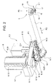
- Fig. 2 shows details of the first pivot arm 4 with the first gripper 5.
- the structure of the second pivot arm 8 with second gripper 9 is identical to the structure of the first pivot arm 4 with gripper 5.
- the first drives 6 consist of a drive 6.1 for the pivoting movement P1 and from a drive 6.2 for the linear movement P2 of the swivel arm 4.
- the drive 6.1 has a driving gear 6.11 drivable by means of a motor 6.10, wherein a rotary encoder 6.12 detects the pinion movement.
- the rotary motion of the pinion gear 6.11 is by means of belt 6.13 on a Pulley 6.14 transferred, which is part of a turntable 6.15, on which the drive 6.2 is arranged for the linear movement P2 of the swing arm 4.
- the first pivot arm 4 is rotatably mounted on a bracket 14 about an axis 14.1, wherein a spring force acts on the pivot arm 4 in the counterclockwise direction.
- a spring force acts on the pivot arm 4 in the counterclockwise direction.
- the leading cable end 3.1 is held by means of a first gripper jaw 16 and a second gripper jaw 17 of the gripper 5.
- the rotatably mounted on an axis 18 jaws 16,17 are opened and closed by means of gear 19.
- FIG. 3 shows the drive 6.2 for the linear movement P2 of the swivel arm 4.
- the swivel arm 4 is guided by means of a arranged on the turntable 6.15 linear guide 6.23, wherein a prism-shaped bearing 6.21 a linear guide 14.3 of the swing arm 4 leads.
- a pinion 6.22 of the arranged on the turntable 6.15 6.20 engine engages in a arranged on the linear guide 14.3 rack 14.4, wherein the rotational movement of the pinion 6.22 is converted into the linear movement P2.
- the holding device 20 can also in a cable processing device with arranged in series processing stations and linearly movable gripper units, such as with the EP 1 073 163 B1 have been disclosed.
- the gripper can move linearly in the transfer direction and linearly transversely to the transfer direction. For example, arranged at the end of the row of processing stations Holding device 20 is fed to the crimp contact by means of grippers and a linear movement in the transfer direction and a linear movement transversely thereto and held by this.
- the gripper grips the cable end and acts on the cable with a force in the cable longitudinal axis by means of a linear movement away from the holding device 20.
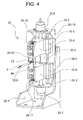
- Fig. 4 shows the holding device 20 and Fig. 5 shows details of the holding device 20 for holding the cable end connection or the crimp contact 15 with the cable 3.
- a arranged on a support 20.15 of a housing 20.1 slide 20.2 leads a lower slide 20.3 with boom 20.4 and an upper slide 20.5 with boom 20.6.
- the lower carriage 20.3 is driven by a lower drive 20.7 and the upper carriage 20.5 is driven by an upper drive 20.8.
- the drives 20.7,20.8 may be, for example, electric or pneumatic drives.
- At the lower arm 20.4 is a lower plate 20.9 and the upper arm 20.6 is an upper plate 20.10 is provided, wherein the holding plates 20.9,20.10 can perform an opening movement or a closing movement by means of the counter-movable carriage 20.3,20.5.
- the holding plates 20.9,20.10 are formed at the free ends of a V-shape and hold after a closing movement the crimp contact 15 with cable 3 fixed.
- the pull-out force AK engages the holding plates 20.9, 20.10 and is transmitted to a lower force sensor 20.11 or to an upper force sensor 20.12.
- Fig. 5 shows the case that the cable end connection or crimp connection of the predetermined pull-out force AK has not withstood.
- the pull-out force AK measured by means of the force sensors 20.11,20.12 or the current of the drive 6.20 has not been reached, the Leiterimpimp 15.1 is faulty.
- opening the holding plates 20.9,20.10 symbolized by the arrow P6
- falls symbolized by the arrow P7 of the crimp contact 15 via a discharge plate 20.13 in a container, not shown.
- Fig. 2 shows how the gripper 5 holds the cable 3 or holds for the loading of the cable 3 with the pull-out force AK.
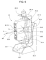
- Figs. 4 to 6 show how the cable end contact or crimp contact 15 is held during the pull-out test.
- the 6 shows a holding device 20 in which the pull-out force AK is measured by means of a force sensor 20.14.
- the force sensor 20.14 is arranged between the housing 20.1 and the carrier 20.15, wherein the pull-out force AK is transmitted to the carrier 20.15 and from there to the force sensor 20.14 and from there to the housing 20.1.
- the arms 20.4,20.6 may also have a plurality of retaining plates 20.9,20.10, wherein the free ends of the holding plate pairs (lower and upper plate) differ depending on festzuhaltendem Jardinenditch.
- the V-shaped ends may vary in shape and size or may be different, with the ends of the retaining plates 20.9, 20.10 guiding the cable 3 in the closing movement, comparable to the V-shaped ends.
Landscapes
- Engineering & Computer Science (AREA)
- Manufacturing & Machinery (AREA)
- Manufacturing Of Electrical Connectors (AREA)
Claims (7)
- Procédé pour faire fonctionner un dispositif de traitement de câble (1) comportant des stations de traitement (7, 10) pour préparer un câble (3), au moins un organe de préhension (5, 9) qui sert de dispositif d'amenée amenant le câble (3) dans les stations de traitement (7, 10),
caractérisé en ce que le mouvement linéaire (P2, P4) de l'organe de préhension (5, 9) qui est produit à l'aide d'un entraînement linéaire (6.2) est utilisé pour amener le câble (3) dans les stations de traitement (7, 10) et pour tester la liaison d'extrémité de câble réalisée par lesdites stations de traitement (7, 10), cette liaison d'extrémité de câble étant amenée vers des plaques de retenue (20.9, 20.10) d'un dispositif de retenue (20) à l'aide de l'organe de préhension (5, 9), lequel organe de préhension (5, 9) saisit le câble (3) et le contraint à l'aide du mouvement linéaire (P2, P4) avec une force d'arrachement (AK) dans le sens longitudinal de l'axe. - Procédé selon la revendication 1, caractérisé en ce que la force d'arrachement (AK) est apte à être mesurée à l'aide d'au moins un capteur de force (20.11, 20.12, 20.14).
- Procédé selon la revendication 1 ou 2, caractérisé en ce que la force d'arrachement (AK) est apte à être définie à l'aide du courant d'un moteur (6.20) qui produit le mouvement linéaire (P2, P4).
- Dispositif de traitement de câble (1) comportant des stations de traitement (7, 10) pour préparer un câble (3), au moins un organe de préhension (5, 9) qui sert de dispositif d'amenée amenant le câble (3) dans les stations de traitement (7, 10) en vue de la réalisation d'une liaison d'extrémité de câble, pour la mise en oeuvre du procédé selon la revendication 1,
caractérisé en ce qu'il est prévu un dispositif de retenue (20) comportant des plaques de retenue (20.9, 20.10) vers lesquelles l'organe de préhension (5, 9) amène un contact (15) de la liaison d'extrémité de câble, pour l'immobiliser, et l'organe de préhension (5, 9) saisit ensuite le câble (3) et le contraint (3) à l'aide d'un mouvement linéaire (P2, P4) d'un entraînement linéaire (6.2) avec une force d'arrachement (AK) dans l'axe longitudinal du câble. - Dispositif de traitement de câble selon la revendication 4, caractérisé en ce que le dispositif de retenue (20) destiné à immobiliser le contact (15) de la liaison d'extrémité de câble comporte des plaques de retenue (20.9, 20.10) qui sont aptes à s'ouvrir et à se fermer grâce à des chariots (20.3, 20.5) mobiles en sens inverse et pourvus d'un bras (20.4, 20.6).
- Dispositif de traitement de câble selon la revendication 5, caractérisé en ce que les plaques de retenue (20.9, 20.10) ont la forme d'un V, à leur extrémité libre, et immobilisent le contact de sertissage (15) avec le câble (3) après un mouvement de fermeture.
- Dispositif de traitement de câble selon l'une des revendications 4 à 6 précédentes, caractérisé en ce que la force d'arrachement (AK) agit au niveau des plaques de retenue (20.9, 20.10) et est apte à être transmise à au moins un capteur de force (20.11, 20.12, 20.14).
Priority Applications (2)
| Application Number | Priority Date | Filing Date | Title |
|---|---|---|---|
| EP04405534A EP1515403B1 (fr) | 2003-09-10 | 2004-08-26 | Dispositif de traitement de câble |
| US10/938,024 US7603768B2 (en) | 2003-09-10 | 2004-09-09 | Inspection apparatus for wire-processing machine |
Applications Claiming Priority (3)
| Application Number | Priority Date | Filing Date | Title |
|---|---|---|---|
| EP03405664 | 2003-09-10 | ||
| EP03405664 | 2003-09-10 | ||
| EP04405534A EP1515403B1 (fr) | 2003-09-10 | 2004-08-26 | Dispositif de traitement de câble |
Publications (3)
| Publication Number | Publication Date |
|---|---|
| EP1515403A2 EP1515403A2 (fr) | 2005-03-16 |
| EP1515403A3 EP1515403A3 (fr) | 2006-05-17 |
| EP1515403B1 true EP1515403B1 (fr) | 2007-10-24 |
Family
ID=34137617
Family Applications (1)
| Application Number | Title | Priority Date | Filing Date |
|---|---|---|---|
| EP04405534A Active EP1515403B1 (fr) | 2003-09-10 | 2004-08-26 | Dispositif de traitement de câble |
Country Status (2)
| Country | Link |
|---|---|
| US (1) | US7603768B2 (fr) |
| EP (1) | EP1515403B1 (fr) |
Families Citing this family (26)
| Publication number | Priority date | Publication date | Assignee | Title |
|---|---|---|---|---|
| EP1515403B1 (fr) | 2003-09-10 | 2007-10-24 | komax Holding AG | Dispositif de traitement de câble |
| DE502004005315D1 (de) * | 2003-09-10 | 2007-12-06 | Komax Holding Ag | Kabelbearbeitungseinrichtung |
| EP1764883B1 (fr) * | 2005-09-19 | 2009-10-21 | komax Holding AG | Système de traitement de câble au moyen d'au moins deux outils |
| EP1786072B1 (fr) * | 2005-11-10 | 2008-07-16 | komax Holding AG | Dispositif de traitement de câble et méthode d'utilisation |
| DE502006001117D1 (de) | 2005-11-10 | 2008-08-28 | Komax Holding Ag | Kabelbearbeitungseinrichtung und Verfahren für den Betrieb einer solchen Kabelbearbeitungseinrichtung |
| JP4413872B2 (ja) * | 2006-01-25 | 2010-02-10 | 矢崎総業株式会社 | 電線端末処理装置における電線セット装置 |
| DE102007018555B4 (de) * | 2007-04-18 | 2009-02-19 | Schäfer Werkzeug- und Sondermaschinenbau GmbH | Kabelbearbeitungseinrichtung |
| CH700897B1 (de) * | 2009-04-24 | 2014-02-14 | Schleuniger Holding Ag | Einrichtung und Verfahren zum Zusammenführen von Leitern zur Herstellung einer Doppelcrimpverbindung. |
| JP5323137B2 (ja) * | 2011-06-14 | 2013-10-23 | ヤマハ発動機株式会社 | 段取り方法、部品実装方法および部品実装システム |
| CN102637988B (zh) * | 2012-04-05 | 2013-11-13 | 东莞市三信精密机械有限公司 | 线缆连接器自动加工焊接组装机 |
| CN102931565B (zh) * | 2012-10-19 | 2014-11-26 | 东莞市三信精密机械有限公司 | 全自动线缆加工设备 |
| RS60560B1 (sr) | 2012-12-03 | 2020-08-31 | Komax Holding Ag | Postavka i postupak za izradu krimpovanog spoja |
| JP5672322B2 (ja) * | 2013-03-14 | 2015-02-18 | 株式会社安川電機 | ロボット装置 |
| CN103166087A (zh) * | 2013-03-21 | 2013-06-19 | 协讯电子(吉安)有限公司 | 一种适用于电缆与连接器的自动焊锡装置平台 |
| CN103166085A (zh) * | 2013-03-21 | 2013-06-19 | 协讯电子(吉安)有限公司 | 一种适用于电源连接器的自动化加锡装置 |
| ITPD20130242A1 (it) * | 2013-09-04 | 2015-03-05 | K M I Trade Societa Resp Limitata | Dispositivo di intestazione delle estremita' libere dei fili da ripresa |
| RS60594B1 (sr) * | 2014-11-18 | 2020-08-31 | Komax Holding Ag | Uređaj za obradu kablova |
| RS58126B1 (sr) * | 2015-07-20 | 2019-02-28 | Komax Holding Ag | Uređaj za obradu kabla |
| US11069462B2 (en) * | 2016-12-15 | 2021-07-20 | The Boeing Company | Automated wire processing system and methods |
| EP3340400B1 (fr) * | 2016-12-22 | 2019-09-11 | Komax Holding Ag | Dispositif et procédé de manipulation d'un conducteur interne |
| US10522960B2 (en) | 2017-05-03 | 2019-12-31 | Te Connectivity Corporation | Crimp quality monitoring method and system for use with a hydraulic crimping apparatus |
| RS61021B1 (sr) | 2017-07-25 | 2020-12-31 | Komax Holding Ag | Uređaj za zamenu alata za krimpovanje, sistem krimp prese i postupak zamene prvog alata za krimpovanje postavljenog u položaj za obradu u krimp presi drugim alatom za krimpovanje |
| EP3447859B1 (fr) * | 2017-08-21 | 2020-10-07 | Aptiv Technologies Limited | Appareil de coupe-fil pour couper un fil et sertir les extrémités |
| EP3522311B1 (fr) * | 2018-02-01 | 2021-05-19 | Aptiv Technologies Limited | Système et procédé d'assemblage assisté |
| CN112106264B (zh) * | 2018-04-24 | 2023-03-24 | 施洛伊尼格股份公司 | 换刀装置,加工机,更换刀具的方法 |
| EP3561970B1 (fr) * | 2018-04-26 | 2023-07-19 | Komax Holding Ag | Dispositif de retenue de l'extrémité de câble destiné à retenir une extrémité de câble et procédé de son positionnement |
Family Cites Families (34)
| Publication number | Priority date | Publication date | Assignee | Title |
|---|---|---|---|---|
| US4852433A (en) * | 1987-05-18 | 1989-08-01 | Mechtrix Corporation | Interlocking blade pair for stripping insulated electrical conductors |
| US4819533A (en) * | 1987-08-11 | 1989-04-11 | Artos Engineering Company | Wire processing apparatus having pushbar and conveyor mechanisms |
| GB8816325D0 (en) * | 1988-07-08 | 1988-08-10 | Amp Great Britain | Wire processing apparatus |
| US4873901A (en) * | 1988-09-16 | 1989-10-17 | Artos Engineering Company | Apparatus for cutting and stripping insulation from wire segments having different gauge conductors |
| US5067379A (en) * | 1989-03-20 | 1991-11-26 | Mechtrix Corporation | Electronic display system for wire stripping machine |
| US5058260A (en) * | 1989-09-18 | 1991-10-22 | Amp Incorporated | Wire processing apparatus |
| US5092026A (en) * | 1989-09-22 | 1992-03-03 | Molex Incorporated | Crimp height monitor |
| US5271254A (en) * | 1989-12-05 | 1993-12-21 | The Whitaker Corporation | Crimped connector quality control method apparatus |
| US5025549A (en) * | 1990-08-31 | 1991-06-25 | Amp Incorporated | Lead making machine having improved wire feeding system |
| US5491994A (en) * | 1991-12-11 | 1996-02-20 | Diamond Die & Mold Company | Crimp height monitor |
| JPH071223A (ja) | 1993-05-06 | 1995-01-06 | Komax Holding Ag | ケーブル加工機械用の切断ストリップ機構 |
| JP2870362B2 (ja) * | 1993-06-11 | 1999-03-17 | 住友電装株式会社 | 連続端子圧着機 |
| US5402566A (en) * | 1994-04-04 | 1995-04-04 | The Whitaker Corporation | Method and machine for attaching an electrical connector to a coaxial cable |
| US5522130A (en) * | 1994-10-13 | 1996-06-04 | Artos Engineering Company | Laser positioning system for wire cutting and stripping apparatus |
| US5937505A (en) * | 1995-03-02 | 1999-08-17 | The Whitaker Corporation | Method of evaluating a crimped electrical connection |
| EP1670109B1 (fr) | 1995-11-06 | 2010-04-28 | Schleuniger Holding AG | Dispositif de dénudage |
| US7257878B2 (en) * | 1995-11-06 | 2007-08-21 | Beat Locher | Continuous cable processing apparatus |
| JP3156841B2 (ja) * | 1996-06-12 | 2001-04-16 | 矢崎総業株式会社 | 端子圧着装置の制御方法 |
| JPH1050449A (ja) * | 1996-07-31 | 1998-02-20 | Yazaki Corp | 端子圧着装置 |
| AU4234397A (en) * | 1996-08-30 | 1998-03-19 | Whitaker Corporation, The | Wire feed and positioning unit |
| US5797299A (en) * | 1996-11-27 | 1998-08-25 | The Whitaker Corporation | Wire cutting and stripping mechanism |
| DE59806973D1 (de) * | 1997-06-12 | 2003-02-27 | Komax Holding Ag Dierikon | Verfahren und Einrichtung zur Herstellung einer Crimpverbindung |
| DE59806982D1 (de) * | 1997-09-11 | 2003-02-27 | Komax Holding Ag Dierikon | Verfahren zur Bestimmung der Qualität einer Crimpverbindung |
| EP0902509B1 (fr) * | 1997-09-11 | 2003-01-22 | Komax Holding Ag | Méthode pour déterminer la qualité d'une connexion sertie |
| DE19843156A1 (de) * | 1998-09-21 | 2000-04-20 | Sle Electronic Gmbh | Verfahren zur Qualitätssicherung von in einer Crimpvorrichtung hergestellten Crimpverbindungen sowie Crimpwerkzeug und Crimpvorrichtung |
| JP2000123950A (ja) * | 1998-10-13 | 2000-04-28 | Yazaki Corp | 自動切断圧着装置 |
| US6487885B2 (en) * | 2000-10-30 | 2002-12-03 | Komax Holding Ag | Method and apparatus for producing a crimped connection |
| JP3908915B2 (ja) * | 2001-03-02 | 2007-04-25 | 矢崎総業株式会社 | シールド電線の編組切断装置及び編組切断方法 |
| EP1341269B1 (fr) * | 2002-02-22 | 2006-10-11 | Komax Holding Ag | Presse de sertissage pour la réalisation de connexions de sertissage |
| DE50305314D1 (de) * | 2002-02-22 | 2006-11-23 | Komax Holding Ag | Crimppresse zur Herstellung einer Crimpverbindung |
| US6782607B2 (en) * | 2002-04-19 | 2004-08-31 | Tyco Electronics Corporation | Wire positioning device apparatus, methods and articles of manufacture |
| JP2004185852A (ja) * | 2002-11-29 | 2004-07-02 | Sumitomo Wiring Syst Ltd | ワイヤーハーネスの製造方法及び端子付電線の接続装置 |
| EP1515403B1 (fr) | 2003-09-10 | 2007-10-24 | komax Holding AG | Dispositif de traitement de câble |
| DE502004005315D1 (de) * | 2003-09-10 | 2007-12-06 | Komax Holding Ag | Kabelbearbeitungseinrichtung |
-
2004
- 2004-08-26 EP EP04405534A patent/EP1515403B1/fr active Active
- 2004-09-09 US US10/938,024 patent/US7603768B2/en not_active Expired - Fee Related
Also Published As
| Publication number | Publication date |
|---|---|
| EP1515403A3 (fr) | 2006-05-17 |
| EP1515403A2 (fr) | 2005-03-16 |
| US7603768B2 (en) | 2009-10-20 |
| US20050050722A1 (en) | 2005-03-10 |
Similar Documents
| Publication | Publication Date | Title |
|---|---|---|
| EP1515403B1 (fr) | Dispositif de traitement de câble | |
| EP1032095B1 (fr) | Méthode et appareil pour usiner et tordre un paire de conducteurs | |
| US4653159A (en) | Flexible automated manufacturing system | |
| EP0117273B1 (fr) | Appareil pour fixer automatiquement des connecteurs à des fins de câbles | |
| EP3257117B1 (fr) | Machine de sertissage | |
| EP0440955B1 (fr) | Dispositif pour le montage automatique de câbles électriques avec pièces de connexion dans des boîtiers de prise | |
| EP2565992B1 (fr) | Dispositif et procédé d'amenée d'extrémités de câble vers des unités de confection | |
| EP1786072B1 (fr) | Dispositif de traitement de câble et méthode d'utilisation | |
| CH663308A5 (de) | Vorrichtung zum herstellen und verarbeiten von drahtstuecken. | |
| EP1447888A1 (fr) | Pince pour un dispositif pour traiter des câbles | |
| EP1775804B1 (fr) | Dispositif pour la production d'un câblage électrique | |
| DE102010017981B4 (de) | Einrichtung und Verfahren zum Zusammenführen von Leitern | |
| CH660819A5 (de) | Vorrichtung zur automatischen fertigung von ankern fuer elektrische kleinmotoren sowie ein verfahren zum betrieb derselben. | |
| EP0182592A2 (fr) | Système de fabrication automatique flexible | |
| DE102016109151B3 (de) | Verdrilleinrichtung | |
| EP2779327B1 (fr) | Pince rotative pour câble et méthode de guidage d'un conducteur électrique | |
| EP1764884A1 (fr) | Presse de sertissage | |
| CN215144204U (zh) | 线束折弯装置 | |
| EP1251605B1 (fr) | Appareil et méthode pour l'insertion de bout de câble dans des boítiers de connecteurs | |
| EP0708508A1 (fr) | Procédé et dispositif pour équiper des boîtiers de connecteurs | |
| EP0844704A2 (fr) | Méthode de fabrication de lignes torsadées confectionnées ainsi que dispositif de mise en oeuvre de la méthode | |
| EP0994539B1 (fr) | Dispositif pour l'assemblage d'un câble | |
| EP1403983B1 (fr) | Dispositif de traitement de câbles avec un dispositif de pivotement pour l'alimentation de postes de travail en extrémités de càbles | |
| DE3330687C2 (fr) | ||
| DE3811435A1 (de) | Verbinderblockzufuehrstation und kabelbaumauswurfstation |
Legal Events
| Date | Code | Title | Description |
|---|---|---|---|
| PUAI | Public reference made under article 153(3) epc to a published international application that has entered the european phase |
Free format text: ORIGINAL CODE: 0009012 |
|
| AK | Designated contracting states |
Kind code of ref document: A2 Designated state(s): AT BE BG CH CY CZ DE DK EE ES FI FR GB GR HU IE IT LI LU MC NL PL PT RO SE SI SK TR |
|
| AX | Request for extension of the european patent |
Extension state: AL HR LT LV MK |
|
| PUAL | Search report despatched |
Free format text: ORIGINAL CODE: 0009013 |
|
| AK | Designated contracting states |
Kind code of ref document: A3 Designated state(s): AT BE BG CH CY CZ DE DK EE ES FI FR GB GR HU IE IT LI LU MC NL PL PT RO SE SI SK TR |
|
| AX | Request for extension of the european patent |
Extension state: AL HR LT LV MK |
|
| 17P | Request for examination filed |
Effective date: 20061028 |
|
| 17Q | First examination report despatched |
Effective date: 20061214 |
|
| AKX | Designation fees paid |
Designated state(s): CH DE FR GB IT LI |
|
| GRAP | Despatch of communication of intention to grant a patent |
Free format text: ORIGINAL CODE: EPIDOSNIGR1 |
|
| GRAS | Grant fee paid |
Free format text: ORIGINAL CODE: EPIDOSNIGR3 |
|
| GRAA | (expected) grant |
Free format text: ORIGINAL CODE: 0009210 |
|
| AK | Designated contracting states |
Kind code of ref document: B1 Designated state(s): CH DE FR GB IT LI |
|
| REG | Reference to a national code |
Ref country code: GB Ref legal event code: FG4D Free format text: NOT ENGLISH |
|
| REG | Reference to a national code |
Ref country code: CH Ref legal event code: EP |
|
| REF | Corresponds to: |
Ref document number: 502004005315 Country of ref document: DE Date of ref document: 20071206 Kind code of ref document: P |
|
| GBT | Gb: translation of ep patent filed (gb section 77(6)(a)/1977) |
Effective date: 20071205 |
|
| REG | Reference to a national code |
Ref country code: CH Ref legal event code: NV Representative=s name: INVENTIO AKTIENGESELLSCHAFT |
|
| ET | Fr: translation filed | ||
| PLBE | No opposition filed within time limit |
Free format text: ORIGINAL CODE: 0009261 |
|
| STAA | Information on the status of an ep patent application or granted ep patent |
Free format text: STATUS: NO OPPOSITION FILED WITHIN TIME LIMIT |
|
| 26N | No opposition filed |
Effective date: 20080725 |
|
| PGFP | Annual fee paid to national office [announced via postgrant information from national office to epo] |
Ref country code: GB Payment date: 20080821 Year of fee payment: 5 |
|
| GBPC | Gb: european patent ceased through non-payment of renewal fee |
Effective date: 20090826 |
|
| PG25 | Lapsed in a contracting state [announced via postgrant information from national office to epo] |
Ref country code: GB Free format text: LAPSE BECAUSE OF NON-PAYMENT OF DUE FEES Effective date: 20090826 |
|
| REG | Reference to a national code |
Ref country code: FR Ref legal event code: PLFP Year of fee payment: 13 |
|
| REG | Reference to a national code |
Ref country code: FR Ref legal event code: PLFP Year of fee payment: 14 |
|
| PGFP | Annual fee paid to national office [announced via postgrant information from national office to epo] |
Ref country code: FR Payment date: 20170822 Year of fee payment: 14 Ref country code: IT Payment date: 20170828 Year of fee payment: 14 Ref country code: DE Payment date: 20170822 Year of fee payment: 14 |
|
| REG | Reference to a national code |
Ref country code: DE Ref legal event code: R119 Ref document number: 502004005315 Country of ref document: DE |
|
| PG25 | Lapsed in a contracting state [announced via postgrant information from national office to epo] |
Ref country code: IT Free format text: LAPSE BECAUSE OF NON-PAYMENT OF DUE FEES Effective date: 20180826 Ref country code: DE Free format text: LAPSE BECAUSE OF NON-PAYMENT OF DUE FEES Effective date: 20190301 |
|
| PG25 | Lapsed in a contracting state [announced via postgrant information from national office to epo] |
Ref country code: FR Free format text: LAPSE BECAUSE OF NON-PAYMENT OF DUE FEES Effective date: 20180831 |
|
| PGFP | Annual fee paid to national office [announced via postgrant information from national office to epo] |
Ref country code: CH Payment date: 20230902 Year of fee payment: 20 |