EP1515185B1 - Herstellungsverfahren für Rollen für Film- oder Bandverarbeitungsmaschinen - Google Patents
Herstellungsverfahren für Rollen für Film- oder Bandverarbeitungsmaschinen Download PDFInfo
- Publication number
- EP1515185B1 EP1515185B1 EP04021346A EP04021346A EP1515185B1 EP 1515185 B1 EP1515185 B1 EP 1515185B1 EP 04021346 A EP04021346 A EP 04021346A EP 04021346 A EP04021346 A EP 04021346A EP 1515185 B1 EP1515185 B1 EP 1515185B1
- Authority
- EP
- European Patent Office
- Prior art keywords
- roller
- convex portions
- film
- tape
- manufacturing
- Prior art date
- Legal status (The legal status is an assumption and is not a legal conclusion. Google has not performed a legal analysis and makes no representation as to the accuracy of the status listed.)
- Expired - Lifetime
Links
Images




Classifications
-
- B—PERFORMING OPERATIONS; TRANSPORTING
- B24—GRINDING; POLISHING
- B24B—MACHINES, DEVICES, OR PROCESSES FOR GRINDING OR POLISHING; DRESSING OR CONDITIONING OF ABRADING SURFACES; FEEDING OF GRINDING, POLISHING, OR LAPPING AGENTS
- B24B1/00—Processes of grinding or polishing; Use of auxiliary equipment in connection with such processes
-
- B—PERFORMING OPERATIONS; TRANSPORTING
- B65—CONVEYING; PACKING; STORING; HANDLING THIN OR FILAMENTARY MATERIAL
- B65H—HANDLING THIN OR FILAMENTARY MATERIAL, e.g. SHEETS, WEBS, CABLES
- B65H27/00—Special constructions, e.g. surface features, of feed or guide rollers for webs
-
- B—PERFORMING OPERATIONS; TRANSPORTING
- B65—CONVEYING; PACKING; STORING; HANDLING THIN OR FILAMENTARY MATERIAL
- B65H—HANDLING THIN OR FILAMENTARY MATERIAL, e.g. SHEETS, WEBS, CABLES
- B65H2404/00—Parts for transporting or guiding the handled material
- B65H2404/10—Rollers
- B65H2404/18—Rollers composed of several layers
- B65H2404/182—Rollers composed of several layers with emery paper like coating (gripping, anti-slip)
-
- Y—GENERAL TAGGING OF NEW TECHNOLOGICAL DEVELOPMENTS; GENERAL TAGGING OF CROSS-SECTIONAL TECHNOLOGIES SPANNING OVER SEVERAL SECTIONS OF THE IPC; TECHNICAL SUBJECTS COVERED BY FORMER USPC CROSS-REFERENCE ART COLLECTIONS [XRACs] AND DIGESTS
- Y10—TECHNICAL SUBJECTS COVERED BY FORMER USPC
- Y10T—TECHNICAL SUBJECTS COVERED BY FORMER US CLASSIFICATION
- Y10T29/00—Metal working
- Y10T29/49—Method of mechanical manufacture
- Y10T29/49544—Roller making
- Y10T29/4956—Fabricating and shaping roller work contacting surface element
-
- Y—GENERAL TAGGING OF NEW TECHNOLOGICAL DEVELOPMENTS; GENERAL TAGGING OF CROSS-SECTIONAL TECHNOLOGIES SPANNING OVER SEVERAL SECTIONS OF THE IPC; TECHNICAL SUBJECTS COVERED BY FORMER USPC CROSS-REFERENCE ART COLLECTIONS [XRACs] AND DIGESTS
- Y10—TECHNICAL SUBJECTS COVERED BY FORMER USPC
- Y10T—TECHNICAL SUBJECTS COVERED BY FORMER US CLASSIFICATION
- Y10T29/00—Metal working
- Y10T29/49—Method of mechanical manufacture
- Y10T29/49544—Roller making
- Y10T29/4956—Fabricating and shaping roller work contacting surface element
- Y10T29/49563—Fabricating and shaping roller work contacting surface element with coating or casting about a core
Definitions
- the present invention relates to a manufacturing method of rollers to be installed on machines for printing film such as photographic film, retorted food pouch sealing films and plastic films, or tape such as fabric tape, paper tape and rubber tape and the like wound on a winding cylinder, or for applying bond and, in particular, relates to a manufacturing method of rollers to be installed on film or tape handling machines for smoothly feeding or changing a feeding direction of film or tape, preventing any shear or shift in a printing of film or tape from happening, and attaining a stable feeding speed, when the rollers are used as feed rollers or guide rollers sliding on the film web and contacting with the film web.
- rollers to be installed on machines for printing film or tape wound around winding cylinders, or applying bond to the film or tape have been manufactured, as shown in Fig 9, by applying a plating 23 on a circumference face of base material 22 of the roller 21 and finishing the circumstance face sliding on the film and tape so as to attain a mirror like condition having no unevenness on its circumstance face.
- EP 0 994 394 A2 discloses a method of manufacturing a mirror-surface cylinder.
- a method of manufacturing a web conveying roller which seeks to provide a roller where air can be vented from between the roller surface and the web.
- the method comprises the steps of applying a layer of nickel onto a metal roller, blasting the surface of the nickel layer with steel shot to create on the surface a deep texture with a pattern of well rounded down features and very sharp up features, grinding the blasted surface to remove the sharp up features and thereby produce plateaus on the surface, and electroplating the surface with a thin layer of chromium after the grinding step to increase the durability of the surface.
- the problem to be solved with the invention is how to feed the film or tape or the like wound around the winding cylinder to the machine through a feeding roller or a guide roller at a constant speed without any shifting or out of its feeding position on the winding cylinder.
- the inventor of the invention invented a manufacturing method of a roller by forming a lot of minute concave portions and convex portions on a circumferential surface of a base material consisting of cylindrical metal such as stainless steel and the like, grinding to remove summits of the convex portions of the concave portions and convex portions, and plating for rising a surface hardness with the thickness of plating determined so as to remain shapes of the concave portions and convex portions, forming a surface coating on the circumferential face of the roller, and grinding summits of convex portions of the plated concave-convex face in order to form minute flat or curved sliding faces of the convex portions.
- the first object of the invention is to feed film or tape wound around a winding cylinder to a machine through a feeding roller or a guide roller without any shifting or out of position of the film or tape on the rollers and the winding cylinder.
- the second object of the invention is to feed at a constant speed film or tape without shifting or out of position on the roller by making a lot of concave portions and convex portions on a circumferential outer face of the roller, as well as forming a flat or curved portions of the convex portions after the circumferential outer face is finally machined, in order to make a contacting area between the outer face and the film or tape and a frictional resistance, respectively small.
- the invention relates to a manufacturing method for the roller to be installed on a machine handling film or tape wound around a winding cylinder, such as printing machines and bag making machines. It is noted that the feed roller above-mentioned includes a press roller having the same function as that of the feed roller.
- the roller according to the invention is made of a base material of metal such as stainless steel and the like, a lot of minute concave and convex portions are formed on an outer circumferential face of cylindrical metal such as stainless steel and the like, summits of the convex portions of the many minute concave-convex portions are ground and removed, a plating process and a coating process for hardening the outer face is applied to the base cylindrical metal at a depth leaving such profiles of concave portions and convex portions, and summits of the convex portions of the concave-convex portions plated and coated are ground forming flat or curved sliding face on the convex portions.
- the invention relates to a manufacturing method of rollers for film or tape or the like by making the final machined face of the convex portions flat or curved sliding ones, lessening the contacting area between the final machined face and the film or tape or the like, and lessening the frictional resistance between the face and film or the like, making a feeding of film or tape or the like to the machine or a changing of its feeding direction able to do without any shifting or out of position of film or tape or the like on the metal cylinder or rollers and attaining a constant speed of feeding or moving of the film or the like.
- the first step of the manufacturing method of the roller according to the invention is a buff grinding step in which the surface of the base material 1 consisting of metal such as stainless steel and the like is ground by a buff so as to control the surface condition (see Fig 1).
- the second step of the manufacturing method of the roller according to the invention is a concave-convex face forming step in which a lot of minute concave portions 2 and convex portions 3 are formed on the surface of the base material 1 buff-ground in the first step by means of a physical means or chemical means (see Fig 2).
- the physical means used in the second step so as to form the concave portions 2 and convex portions 3 is, for example, a shot blasting process using whetstone striking the surface of the base material 1 with a predetermined pressure.
- a shot blasting machine sprays sand grains onto the surface of the base material 1 forming a number of minute concave portions 2 and convex portions 3 on the surface of the base material 1.
- the sizes of the concave portions 2 and the convex portions 3 are predetermined according to characters of the film or tape to be transferred along the concave-convex portions. It is not necessary particularly to restrict the sizes and preferably in general the sand blasting process employing grain sizes of No. 10 - 2000 is used so as to form the concave portions 2 and the convex portions 3 of sizes less than 10 micrometer.
- the manufacturing method of the invention can employ dry type shot blasting process and wet type shot blasting process.
- the chemical means for forming a lot of minute concave portions 2 and convex portions 3 on the base material 1 are a chemical etching process forming these concave portions 2 and convex portions 3 by etching the base material with chemical agent, a wet plating, and a micro-porous plating, these chemical means can be employed to the manufacturing method according to the invention.
- the third step of the manufacturing method is a grinding one grinding and removing the summits 3a of many convex portions 3 formed on the base material 1 in the second step (see Fig 3).
- the fourth step 4 of the invention consists of an applying of plating and coating on the surface of base material 1 after the tops or summits 3a of convex portions 3 are ground and removed in the third step, as shown in Fig 4, so as to leave the shapes or profiles of the concave portions 2 and convex portions 3 and additionally form a surface coating 4 thereon.
- the plating operation mentioned above is preferably hard type chrome plating.
- tops 4a of the convex portions 3 of the concave-convex portions 2 and 3 formed on the surface coating 4 processed in the plating step of the fourth step are ground by means of thread buff and whetstone.
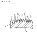
- the fifth step is a surface grinding and finishing one, in which the convex portions 3 formed on surface of the roller 6 are machined to form flat type sliding faces 5 (see Fig 5). It is noted that instead of the flat type sliding faces 5, curved shape sliding faces 5a (see Fig 6) are formed on the convex portions 3.
- bosses 8 for revolving the roller 6 are inserted and fixed at both ends of the roller 6 after the manufacturing steps above are carried out, and the roller machine 9 is obtained.
- the roller machine 9 is used as a feed roller 6a and a guide roller 6b installed between a machine M, for example, of a printer and a winding cylinder 10 on which film or tape 7 or the like is wound.
- rollers of the invention are used as a feed roller 6a and a guide roller 6b of the machine M, because that a lot of minute concave portions 2 and convex portions 3 are continuously formed on the base material 1 of the roller, surfaces of the concave portions 2 and convex portions 3 are plated and coated, and surfaces of tops of the convex portions 3 are flatly finished obtaining the sliding face 5 (see Fig 5), or surfaces of tops of the convex portions 3 are curved in a shape of the sliding face 5a (see Fig 6), a film or tape 7 contacts only the small area of the sliding faces 5, 5a, comparing to that of the conventional mirror like contact, resulting in a small frictional resistance between the film or tape 7 or the sliding faces 5, 5a.
- the air within the concave portions 2 functions as a cushion and the film or tape 7 fails to enter into the concave portions 2, resulting in the good slidability and good separatability between the film or tape 7 and the roller surface.
- the film or tape 7 is fed and changes its feeding direction smoothly when the film web slides on the sliding faces 5, 5a of the roller 6, resulting in no shift of the film or tape 7 along the surface of the roller 6 or winding cylinder and a constant speed transferring of the film or tape or the like.
- roller 6 when the roller 6 is used after it is manufactured by these five steps, it is possible to feed and change smoothly the transferring direction of the film or tape or the like 7 without scratching of the film or tape or the like 7.
- the manufacturing method of the roller of the invention has characteristics, so the invention has the effect detailed below.
- the roller manufactured in accordance with the invention When the roller manufactured in accordance with the invention is used as a feed roller or a guide roller of the machine handling film webs and the like, a contacting area between the film web and the sliding face of the convex portions formed on the surface of the roller becomes very small end as a result a frictional resistance between them lessen. So, the film web sliding along the surface of the roller and contacting with the convex portions on the surface fails to shift or move out of position on the roller smoothly at a constant speed. As a result, the film web or the like is machined precisely, so that the machining work can be done effectively.
Landscapes
- Engineering & Computer Science (AREA)
- Mechanical Engineering (AREA)
- Rolls And Other Rotary Bodies (AREA)
- Registering, Tensioning, Guiding Webs, And Rollers Therefor (AREA)
- Shaping Of Tube Ends By Bending Or Straightening (AREA)
- Reduction Rolling/Reduction Stand/Operation Of Reduction Machine (AREA)
- Processing And Handling Of Plastics And Other Materials For Molding In General (AREA)
- Casting Or Compression Moulding Of Plastics Or The Like (AREA)
Claims (3)
- Verfahren zum Herstellen einer Walze (6), die in einer Maschine (9) zu installieren ist, die einen Film oder ein Band (7) oder dergleichen verarbeitet, wobei das Verfahren Folgendes aufweist: einen ersten Schritt des Polierschleifens einer Oberfläche eines Grundmaterials (1) einer Metallwalze, einen zweiten Schritt des Ausbildens mehrerer winziger konkaver Abschnitte (2) und konvexer Abschnitte (3) in der Oberfläche des Grundmaterials (1), einen dritten Schritt des Schleifens und Entfernens von Kuppen (3a) konvexer Abschnitte der mehreren winzigen konkaven Abschnitte (2) und konvexen Abschnitte (3), die jeweils durch den zweiten Schritt entstanden sind, und einen vierten Schritt des Plattierens und Beschichtens des Grundmaterials (1) der Walze, um die Formen der konkaven Abschnitte (2) und konvexen Abschnitte (3) beizubehalten.
- Herstellungsverfahren nach Anspruch 1, des Weiteren mit einem fünften Schritt des Schleifens von Enden der konvexen Abschnitte (3) der konkaven Abschnitte (2) und konvexen Abschnitte (3), die durch den vierten Schritt plattiert und beschichtet wurden, und des Ausbildens flacher Gleitflächen (5) oder gekrümmter Gleitflächen (5a) auf den Kuppen (3a) der konvexen Abschnitte (3).
- Herstellungsverfahren nach Anspruch 1 oder 2, wobei in dem zweiten Schritt die mehreren winzigen konkaven Abschnitte (2) und konvexen Abschnitte (3) auf der Oberfläche des Grundmaterials (1) der Metallwalze (6) mittels Kugelstrahlen oder Maschinenschleifen oder Maschinenschneiden oder Elektrolytschleifen oder chemischem Schleifen oder Nassgalvanisierung oder Mikroporengalvanisierung ausgebildet werden.
Applications Claiming Priority (2)
| Application Number | Priority Date | Filing Date | Title |
|---|---|---|---|
| JP2003316521A JP4064899B2 (ja) | 2003-09-09 | 2003-09-09 | フィルム基材またはテープ基材の加工機械に設置するローラーの製造方法 |
| JP2003316521 | 2003-09-09 |
Publications (2)
| Publication Number | Publication Date |
|---|---|
| EP1515185A1 EP1515185A1 (de) | 2005-03-16 |
| EP1515185B1 true EP1515185B1 (de) | 2007-11-14 |
Family
ID=34131955
Family Applications (1)
| Application Number | Title | Priority Date | Filing Date |
|---|---|---|---|
| EP04021346A Expired - Lifetime EP1515185B1 (de) | 2003-09-09 | 2004-09-08 | Herstellungsverfahren für Rollen für Film- oder Bandverarbeitungsmaschinen |
Country Status (5)
| Country | Link |
|---|---|
| US (1) | US6971946B2 (de) |
| EP (1) | EP1515185B1 (de) |
| JP (1) | JP4064899B2 (de) |
| AT (1) | ATE378148T1 (de) |
| DE (1) | DE602004010019T2 (de) |
Families Citing this family (9)
| Publication number | Priority date | Publication date | Assignee | Title |
|---|---|---|---|---|
| US20070137037A1 (en) * | 2005-12-19 | 2007-06-21 | Noble Craig A | Controlled surface modification as an intermediate step in the surface texturing of work rolls |
| US20070137038A1 (en) * | 2005-12-19 | 2007-06-21 | Barr Rodney S | Work rolls having an engineered surface texture prepared by controlled surface modification after chrome coating |
| JP2007258240A (ja) * | 2006-03-20 | 2007-10-04 | Tokyo Electron Ltd | 表面処理方法 |
| KR20070117348A (ko) * | 2006-06-08 | 2007-12-12 | 에스케이씨하스디스플레이필름(주) | 프리즘시트 제조용 금형 및 그 제조방법 |
| WO2014013922A1 (ja) * | 2012-07-19 | 2014-01-23 | 日産化学工業株式会社 | 防汚性を有する凹凸形状の表面を有する構造体及びその製造方法 |
| EP2910506B1 (de) * | 2012-10-19 | 2018-07-18 | Sato Holdings Kabushiki Kaisha | Walze mit elastischem körper |
| KR101747587B1 (ko) | 2013-03-15 | 2017-06-14 | 노벨리스 인크. | 감쇄된 광택 마감을 갖는 압연 표면 |
| ES2673602T3 (es) * | 2014-10-13 | 2018-06-25 | Fabio Perini S.P.A. | Rodillo para procesar un material en banda continuo y dispositivo que comprende dicho rodillo |
| US9682838B2 (en) * | 2015-03-19 | 2017-06-20 | Pearl Technologies, Inc. | Stationary idler roll with low coefficient of friction |
Citations (2)
| Publication number | Priority date | Publication date | Assignee | Title |
|---|---|---|---|---|
| EP0373482A2 (de) * | 1988-12-12 | 1990-06-20 | EASTMAN KODAK COMPANY (a New Jersey corporation) | Bahnführungsrolle aus Aluminium und Verfahren zu deren Herstellung |
| EP0373481A2 (de) * | 1988-12-12 | 1990-06-20 | Eastman Kodak Company | Bahnführungsrolle und Verfahren zu dessen Herstellung |
Family Cites Families (11)
| Publication number | Priority date | Publication date | Assignee | Title |
|---|---|---|---|---|
| US1952655A (en) * | 1930-10-09 | 1934-03-27 | L D Wright | Polishing device for printing press rollers |
| US3435500A (en) * | 1964-10-14 | 1969-04-01 | Xerox Corp | Pressure roll and method of manufacturing |
| US3451112A (en) * | 1966-12-07 | 1969-06-24 | Bingham Co Samuel | Rubber covered steel mill rollers |
| US3635158A (en) * | 1969-10-06 | 1972-01-18 | William D Budinger | Roller for printing press |
| US3728776A (en) * | 1971-04-19 | 1973-04-24 | L Defazio | Epoxy coating of refurbished balls |
| DE2917550A1 (de) * | 1979-04-30 | 1980-11-06 | Agfa Gevaert Ag | Fotografische sofortbildkamera |
| US4340450A (en) * | 1980-07-09 | 1982-07-20 | Shinku Laboratory Co., Ltd. | Method for plating rollers and apparatus for mounting rollers utilized in the method |
| IT1144107B (it) * | 1981-02-24 | 1986-10-29 | Olivetti & Co Spa | Copiatrice elettrofotografica |
| JPH0698851B2 (ja) * | 1988-06-15 | 1994-12-07 | 新日本製鐵株式会社 | 平版印刷機の湿し水給水ローラ |
| JP2000122310A (ja) * | 1998-10-14 | 2000-04-28 | Nisshin Unyu Kogyo Kk | 複写機等感光ドラム用鏡面管の製造方法 |
| JP2002174861A (ja) * | 2000-12-06 | 2002-06-21 | Anritsu Corp | 感光フィルムの支持ローラ及びその製造方法 |
-
2003
- 2003-09-09 JP JP2003316521A patent/JP4064899B2/ja not_active Expired - Lifetime
-
2004
- 2004-09-02 US US10/931,966 patent/US6971946B2/en not_active Expired - Lifetime
- 2004-09-08 DE DE602004010019T patent/DE602004010019T2/de not_active Expired - Lifetime
- 2004-09-08 AT AT04021346T patent/ATE378148T1/de not_active IP Right Cessation
- 2004-09-08 EP EP04021346A patent/EP1515185B1/de not_active Expired - Lifetime
Patent Citations (2)
| Publication number | Priority date | Publication date | Assignee | Title |
|---|---|---|---|---|
| EP0373482A2 (de) * | 1988-12-12 | 1990-06-20 | EASTMAN KODAK COMPANY (a New Jersey corporation) | Bahnführungsrolle aus Aluminium und Verfahren zu deren Herstellung |
| EP0373481A2 (de) * | 1988-12-12 | 1990-06-20 | Eastman Kodak Company | Bahnführungsrolle und Verfahren zu dessen Herstellung |
Also Published As
| Publication number | Publication date |
|---|---|
| JP4064899B2 (ja) | 2008-03-19 |
| DE602004010019T2 (de) | 2008-09-11 |
| JP2005081388A (ja) | 2005-03-31 |
| US6971946B2 (en) | 2005-12-06 |
| US20050050729A1 (en) | 2005-03-10 |
| EP1515185A1 (de) | 2005-03-16 |
| DE602004010019D1 (de) | 2007-12-27 |
| ATE378148T1 (de) | 2007-11-15 |
Similar Documents
| Publication | Publication Date | Title |
|---|---|---|
| EP0373481B1 (de) | Bahnführungsrolle und Verfahren zu dessen Herstellung | |
| US5366525A (en) | Manufacture of abrasive tape | |
| US6971946B2 (en) | Manufacturing method of roller of film or tape handling machine | |
| US20080276861A1 (en) | Coating rod and producing method therefor | |
| JP7106416B2 (ja) | エンボス成形用シリコーンゴムローラー、それを用いたプラスチックフィルムの製造方法および製造装置、ならびに表面保護フィルム | |
| RU2717763C2 (ru) | Абразивный продукт и способ его изготовления | |
| JP4936992B2 (ja) | 紙送り用ロールの製法 | |
| US4977656A (en) | Nickel coated shot blasted web conveying roller | |
| US4875262A (en) | Process for manufacturing a grain chill roller | |
| US4970768A (en) | Shot blasted web conveying roller | |
| EP0373480A2 (de) | Bahnführungsrolle aus Stahl und Verfahren zu deren Herstellung | |
| JP2683123B2 (ja) | アルミニウムローラ及びその製造方法 | |
| EP1309423B1 (de) | Endbearbeitung von metallischen oberflächen | |
| KR20140037365A (ko) | 초고속 용사방식을 이용한 그라비어 인쇄 롤의 제조방법 및 그라비어 인쇄 롤 | |
| US5316536A (en) | Photoreceptor drum substrate and a method of manufacturing the same | |
| JP2004249186A (ja) | 塗布方法およびコーティングフィルムの製造方法 | |
| EP1038818A2 (de) | Antriebsrad zum Fördern eines Blattes | |
| EP0553429A1 (de) | Transportrolle mit gestrahlter Oberfläche | |
| US20040144304A1 (en) | Rod for coating machine and method for producing the same | |
| JP4193513B2 (ja) | ラッピング加工装置 | |
| JPH0722773B2 (ja) | セラミックス被膜を有する金属ストリップ搬送用ロールの表面加工方法 | |
| CN111971148A (zh) | 用于研磨的方法和设备以及产品和所述产品的用途 | |
| JPH0731750U (ja) | スリッター装置 | |
| JPH0610741B2 (ja) | 写真印画紙用支持体樹脂被覆層のマツト型づけ加工方法 | |
| JPH02158392A (ja) | 印刷インキ転写体及びその製造方法並びにその成形機 |
Legal Events
| Date | Code | Title | Description |
|---|---|---|---|
| PUAI | Public reference made under article 153(3) epc to a published international application that has entered the european phase |
Free format text: ORIGINAL CODE: 0009012 |
|
| AK | Designated contracting states |
Kind code of ref document: A1 Designated state(s): AT BE BG CH CY CZ DE DK EE ES FI FR GB GR HU IE IT LI LU MC NL PL PT RO SE SI SK TR |
|
| AX | Request for extension of the european patent |
Extension state: AL HR LT LV MK |
|
| 17P | Request for examination filed |
Effective date: 20050824 |
|
| RIC1 | Information provided on ipc code assigned before grant |
Ipc: 7G 03B 1/32 B Ipc: 7B 65H 27/00 B Ipc: 7B 24B 1/00 A |
|
| AKX | Designation fees paid |
Designated state(s): AT BE BG CH CY CZ DE DK EE ES FI FR GB GR HU IE IT LI LU MC NL PL PT RO SE SI SK TR |
|
| GRAP | Despatch of communication of intention to grant a patent |
Free format text: ORIGINAL CODE: EPIDOSNIGR1 |
|
| GRAS | Grant fee paid |
Free format text: ORIGINAL CODE: EPIDOSNIGR3 |
|
| RAP1 | Party data changed (applicant data changed or rights of an application transferred) |
Owner name: CHIYODA DAIICHIKOGYO KABUSHIKIKAISHA |
|
| GRAA | (expected) grant |
Free format text: ORIGINAL CODE: 0009210 |
|
| AK | Designated contracting states |
Kind code of ref document: B1 Designated state(s): AT BE BG CH CY CZ DE DK EE ES FI FR GB GR HU IE IT LI LU MC NL PL PT RO SE SI SK TR |
|
| REG | Reference to a national code |
Ref country code: GB Ref legal event code: FG4D |
|
| REG | Reference to a national code |
Ref country code: CH Ref legal event code: EP |
|
| REG | Reference to a national code |
Ref country code: IE Ref legal event code: FG4D |
|
| REF | Corresponds to: |
Ref document number: 602004010019 Country of ref document: DE Date of ref document: 20071227 Kind code of ref document: P |
|
| REG | Reference to a national code |
Ref country code: CH Ref legal event code: NV Representative=s name: WERNER BRUDERER PATENTANWALT |
|
| PG25 | Lapsed in a contracting state [announced via postgrant information from national office to epo] |
Ref country code: NL Free format text: LAPSE BECAUSE OF FAILURE TO SUBMIT A TRANSLATION OF THE DESCRIPTION OR TO PAY THE FEE WITHIN THE PRESCRIBED TIME-LIMIT Effective date: 20071114 Ref country code: SE Free format text: LAPSE BECAUSE OF FAILURE TO SUBMIT A TRANSLATION OF THE DESCRIPTION OR TO PAY THE FEE WITHIN THE PRESCRIBED TIME-LIMIT Effective date: 20080214 Ref country code: ES Free format text: LAPSE BECAUSE OF FAILURE TO SUBMIT A TRANSLATION OF THE DESCRIPTION OR TO PAY THE FEE WITHIN THE PRESCRIBED TIME-LIMIT Effective date: 20080225 |
|
| NLV1 | Nl: lapsed or annulled due to failure to fulfill the requirements of art. 29p and 29m of the patents act | ||
| ET | Fr: translation filed | ||
| PG25 | Lapsed in a contracting state [announced via postgrant information from national office to epo] |
Ref country code: SI Free format text: LAPSE BECAUSE OF FAILURE TO SUBMIT A TRANSLATION OF THE DESCRIPTION OR TO PAY THE FEE WITHIN THE PRESCRIBED TIME-LIMIT Effective date: 20071114 Ref country code: BG Free format text: LAPSE BECAUSE OF FAILURE TO SUBMIT A TRANSLATION OF THE DESCRIPTION OR TO PAY THE FEE WITHIN THE PRESCRIBED TIME-LIMIT Effective date: 20080214 Ref country code: PL Free format text: LAPSE BECAUSE OF FAILURE TO SUBMIT A TRANSLATION OF THE DESCRIPTION OR TO PAY THE FEE WITHIN THE PRESCRIBED TIME-LIMIT Effective date: 20071114 Ref country code: FI Free format text: LAPSE BECAUSE OF FAILURE TO SUBMIT A TRANSLATION OF THE DESCRIPTION OR TO PAY THE FEE WITHIN THE PRESCRIBED TIME-LIMIT Effective date: 20071114 |
|
| PG25 | Lapsed in a contracting state [announced via postgrant information from national office to epo] |
Ref country code: AT Free format text: LAPSE BECAUSE OF FAILURE TO SUBMIT A TRANSLATION OF THE DESCRIPTION OR TO PAY THE FEE WITHIN THE PRESCRIBED TIME-LIMIT Effective date: 20071114 |
|
| PG25 | Lapsed in a contracting state [announced via postgrant information from national office to epo] |
Ref country code: CZ Free format text: LAPSE BECAUSE OF FAILURE TO SUBMIT A TRANSLATION OF THE DESCRIPTION OR TO PAY THE FEE WITHIN THE PRESCRIBED TIME-LIMIT Effective date: 20071114 Ref country code: DK Free format text: LAPSE BECAUSE OF FAILURE TO SUBMIT A TRANSLATION OF THE DESCRIPTION OR TO PAY THE FEE WITHIN THE PRESCRIBED TIME-LIMIT Effective date: 20071114 |
|
| PG25 | Lapsed in a contracting state [announced via postgrant information from national office to epo] |
Ref country code: SK Free format text: LAPSE BECAUSE OF FAILURE TO SUBMIT A TRANSLATION OF THE DESCRIPTION OR TO PAY THE FEE WITHIN THE PRESCRIBED TIME-LIMIT Effective date: 20071114 Ref country code: BE Free format text: LAPSE BECAUSE OF FAILURE TO SUBMIT A TRANSLATION OF THE DESCRIPTION OR TO PAY THE FEE WITHIN THE PRESCRIBED TIME-LIMIT Effective date: 20071114 Ref country code: RO Free format text: LAPSE BECAUSE OF FAILURE TO SUBMIT A TRANSLATION OF THE DESCRIPTION OR TO PAY THE FEE WITHIN THE PRESCRIBED TIME-LIMIT Effective date: 20071114 |
|
| PLBE | No opposition filed within time limit |
Free format text: ORIGINAL CODE: 0009261 |
|
| STAA | Information on the status of an ep patent application or granted ep patent |
Free format text: STATUS: NO OPPOSITION FILED WITHIN TIME LIMIT |
|
| PG25 | Lapsed in a contracting state [announced via postgrant information from national office to epo] |
Ref country code: PT Free format text: LAPSE BECAUSE OF FAILURE TO SUBMIT A TRANSLATION OF THE DESCRIPTION OR TO PAY THE FEE WITHIN THE PRESCRIBED TIME-LIMIT Effective date: 20080414 |
|
| 26N | No opposition filed |
Effective date: 20080815 |
|
| PG25 | Lapsed in a contracting state [announced via postgrant information from national office to epo] |
Ref country code: GR Free format text: LAPSE BECAUSE OF FAILURE TO SUBMIT A TRANSLATION OF THE DESCRIPTION OR TO PAY THE FEE WITHIN THE PRESCRIBED TIME-LIMIT Effective date: 20080215 |
|
| PG25 | Lapsed in a contracting state [announced via postgrant information from national office to epo] |
Ref country code: EE Free format text: LAPSE BECAUSE OF FAILURE TO SUBMIT A TRANSLATION OF THE DESCRIPTION OR TO PAY THE FEE WITHIN THE PRESCRIBED TIME-LIMIT Effective date: 20071114 Ref country code: MC Free format text: LAPSE BECAUSE OF NON-PAYMENT OF DUE FEES Effective date: 20080930 |
|
| PG25 | Lapsed in a contracting state [announced via postgrant information from national office to epo] |
Ref country code: CY Free format text: LAPSE BECAUSE OF FAILURE TO SUBMIT A TRANSLATION OF THE DESCRIPTION OR TO PAY THE FEE WITHIN THE PRESCRIBED TIME-LIMIT Effective date: 20071114 Ref country code: IE Free format text: LAPSE BECAUSE OF NON-PAYMENT OF DUE FEES Effective date: 20080908 |
|
| REG | Reference to a national code |
Ref country code: CH Ref legal event code: NV Representative=s name: FREI PATENTANWALTSBUERO AG |
|
| PG25 | Lapsed in a contracting state [announced via postgrant information from national office to epo] |
Ref country code: HU Free format text: LAPSE BECAUSE OF FAILURE TO SUBMIT A TRANSLATION OF THE DESCRIPTION OR TO PAY THE FEE WITHIN THE PRESCRIBED TIME-LIMIT Effective date: 20080515 Ref country code: LU Free format text: LAPSE BECAUSE OF NON-PAYMENT OF DUE FEES Effective date: 20080908 |
|
| PG25 | Lapsed in a contracting state [announced via postgrant information from national office to epo] |
Ref country code: TR Free format text: LAPSE BECAUSE OF FAILURE TO SUBMIT A TRANSLATION OF THE DESCRIPTION OR TO PAY THE FEE WITHIN THE PRESCRIBED TIME-LIMIT Effective date: 20071114 |
|
| REG | Reference to a national code |
Ref country code: DE Ref legal event code: R082 Ref document number: 602004010019 Country of ref document: DE Representative=s name: MEISSNER, BOLTE & PARTNER GBR, DE Ref country code: DE Ref legal event code: R082 Ref document number: 602004010019 Country of ref document: DE Representative=s name: MEISSNER BOLTE PATENTANWAELTE RECHTSANWAELTE P, DE |
|
| REG | Reference to a national code |
Ref country code: DE Ref legal event code: R082 Ref document number: 602004010019 Country of ref document: DE Representative=s name: MEISSNER, BOLTE & PARTNER GBR, DE |
|
| REG | Reference to a national code |
Ref country code: FR Ref legal event code: PLFP Year of fee payment: 13 |
|
| REG | Reference to a national code |
Ref country code: FR Ref legal event code: PLFP Year of fee payment: 14 |
|
| REG | Reference to a national code |
Ref country code: FR Ref legal event code: PLFP Year of fee payment: 15 |
|
| REG | Reference to a national code |
Ref country code: CH Ref legal event code: PCAR Free format text: NEW ADDRESS: POSTFACH, 8032 ZUERICH (CH) |
|
| PGFP | Annual fee paid to national office [announced via postgrant information from national office to epo] |
Ref country code: IT Payment date: 20230920 Year of fee payment: 20 Ref country code: GB Payment date: 20230926 Year of fee payment: 20 |
|
| PGFP | Annual fee paid to national office [announced via postgrant information from national office to epo] |
Ref country code: FR Payment date: 20230926 Year of fee payment: 20 Ref country code: DE Payment date: 20230929 Year of fee payment: 20 |
|
| PGFP | Annual fee paid to national office [announced via postgrant information from national office to epo] |
Ref country code: CH Payment date: 20231002 Year of fee payment: 20 |
|
| REG | Reference to a national code |
Ref country code: DE Ref legal event code: R071 Ref document number: 602004010019 Country of ref document: DE |
|
| REG | Reference to a national code |
Ref country code: CH Ref legal event code: PL |
|
| REG | Reference to a national code |
Ref country code: GB Ref legal event code: PE20 Expiry date: 20240907 |
|
| PG25 | Lapsed in a contracting state [announced via postgrant information from national office to epo] |
Ref country code: GB Free format text: LAPSE BECAUSE OF EXPIRATION OF PROTECTION Effective date: 20240907 |
|
| PG25 | Lapsed in a contracting state [announced via postgrant information from national office to epo] |
Ref country code: GB Free format text: LAPSE BECAUSE OF EXPIRATION OF PROTECTION Effective date: 20240907 |