EP1514702A1 - Fahrzeugrad mit einem Notlaufstützkörper - Google Patents
Fahrzeugrad mit einem Notlaufstützkörper Download PDFInfo
- Publication number
- EP1514702A1 EP1514702A1 EP03020391A EP03020391A EP1514702A1 EP 1514702 A1 EP1514702 A1 EP 1514702A1 EP 03020391 A EP03020391 A EP 03020391A EP 03020391 A EP03020391 A EP 03020391A EP 1514702 A1 EP1514702 A1 EP 1514702A1
- Authority
- EP
- European Patent Office
- Prior art keywords
- openings
- ellipse
- vehicle wheel
- annular body
- emergency running
- Prior art date
- Legal status (The legal status is an assumption and is not a legal conclusion. Google has not performed a legal analysis and makes no representation as to the accuracy of the status listed.)
- Granted
Links
- 238000005452 bending Methods 0.000 claims abstract 2
- 238000004519 manufacturing process Methods 0.000 claims description 10
- 238000005096 rolling process Methods 0.000 claims 1
- 238000000034 method Methods 0.000 abstract description 5
- 230000015556 catabolic process Effects 0.000 description 5
- 238000009826 distribution Methods 0.000 description 3
- 230000037237 body shape Effects 0.000 description 1
- 230000006378 damage Effects 0.000 description 1
- 230000001771 impaired effect Effects 0.000 description 1
- 238000003698 laser cutting Methods 0.000 description 1
- BASFCYQUMIYNBI-UHFFFAOYSA-N platinum Chemical compound [Pt] BASFCYQUMIYNBI-UHFFFAOYSA-N 0.000 description 1
Images

Classifications
-
- B—PERFORMING OPERATIONS; TRANSPORTING
- B60—VEHICLES IN GENERAL
- B60C—VEHICLE TYRES; TYRE INFLATION; TYRE CHANGING; CONNECTING VALVES TO INFLATABLE ELASTIC BODIES IN GENERAL; DEVICES OR ARRANGEMENTS RELATED TO TYRES
- B60C17/00—Tyres characterised by means enabling restricted operation in damaged or deflated condition; Accessories therefor
- B60C17/04—Tyres characterised by means enabling restricted operation in damaged or deflated condition; Accessories therefor utilising additional non-inflatable supports which become load-supporting in emergency
- B60C17/06—Tyres characterised by means enabling restricted operation in damaged or deflated condition; Accessories therefor utilising additional non-inflatable supports which become load-supporting in emergency resilient
-
- B—PERFORMING OPERATIONS; TRANSPORTING
- B21—MECHANICAL METAL-WORKING WITHOUT ESSENTIALLY REMOVING MATERIAL; PUNCHING METAL
- B21D—WORKING OR PROCESSING OF SHEET METAL OR METAL TUBES, RODS OR PROFILES WITHOUT ESSENTIALLY REMOVING MATERIAL; PUNCHING METAL
- B21D53/00—Making other particular articles
- B21D53/16—Making other particular articles rings, e.g. barrel hoops
Definitions
- the invention relates to a vehicle wheel with a pneumatic tire mounted on a wheel rim and a Notlaufstütz redesign, which is designed as a cup-shaped annular body and itself with its two axially outer edge regions via annular support elements on the Wheel rim supported.
- a major disadvantage of tubeless pneumatic tires is the possible occurrence of a Leakage, causing the tire pressure to drop and the tire to collapse. at A high vehicle speed can be the sudden escape of air in the tire lead to dangerous situations in which the driver takes control of his vehicle loses. Furthermore, the tire can be damaged in a pressure loss that the vehicle rim cuts into the inner liner and overlying layers.
- DE 197 07 090 A1 discloses a vehicle wheel with a supported within the pneumatic tire cavity on the rim runflat support body, which is formed from a cup-shaped annular body.
- the runflat support body is supported by one or more support elements on the rim.
- the support elements go over into the cup-shaped annular body and are either part of the same or consist of a different material compared to the cup-shaped annular body.
- a cup-shaped annular body is disposed within the pneumatic tire cavity.
- the two axially outer edge regions of the emergency running support based on two elastic annular support elements on the rim from.
- the support elements have in radial and axial direction different elasticity parameters and are with the metallic emergency running support materially connected.
- the emergency running support is as a slotted ring body with an opening slot extending in the axial direction trained, whereby the mounting on the rim is made possible. Of the Emergency running support is pulled apart in the area of the opening slot and then screwed into the tire cavity. The opening slot is then over one or more flanges connected.
- a disadvantage of the emergency running bodies is that the filling of a tire with an emergency running a relatively long time to complete, since the compressed air from Cavity of the emergency running support body in the cavity between the emergency running support body and Must reach the inside of the tire. It should be noted that the emergency running support in the event of a breakdown has to absorb a high load and the strength of the emergency running support body can not be lowered.
- the invention is based on the object, an emergency running support for a pneumatic tire to create, which allows a fast filling of the pneumatic tire with compressed air and at the same time not significantly the strength properties of the emergency running support impaired.
- annular body has openings in the form of an ellipse.
- the Openings in the form of ellipses can be used in the event of a breakdown optimally absorb and give the emergency running support thereby a high Fatigue strength.
- Another key advantage of the openings in the form of ellipses lies in the production of the emergency running support. During the forming process of the metallic Ring body occur voltage peaks at the openings in the ring body.
- the main axes the openings in the form of an ellipse substantially in the circumferential direction of Emergency running support are aligned.
- the greatest strains in the circumferential direction of the annular body In the manufacture of the ring body occur the greatest strains in the circumferential direction of the annular body.
- the orientation of the Main axis of the ellipse in the circumferential direction of the ring body results in the forming process an optimal stress distribution in the bearing.
- the Openings in the form of an ellipse in the inner width region of the annular body are arranged.
- the internal width range exposed to a particularly high stress which is why the openings in the form of a Ellipse are preferably arranged in this area.
- the length the major axis of the opening is in the form of an ellipse between 5 and 20 mm. This Length range is in terms of the lowest possible strength reduction than to look optimal.
- the Ratio of major axis to minor axis of the aperture in the form of an ellipse between 1.1 and 1.6.
- FIG. 1 shows a vehicle wheel with emergency running support 1 according to the invention Radial section.
- the runflat support 1, which is rotationally symmetric, is in the tire cavity 8 of the pneumatic tire 9 is arranged and supported by the two annular support elements 2a and 2b on a conventional vehicle rim 10 from.
- the emergency running support 1 consists essentially of the two support elements 2a and 2b and the cup-shaped Ring body 3.
- the openings in the ring body are located at positions 11, 12, 13 and 14. At the positions 11 and 12 are successively in the circumferential direction of Ring body each circular openings in the outer width range of Ring body 3. In the area of the radial constriction 4 are on the circumference of the Ring body distributes each openings in the form of ellipses in positions 13 and 14th arranged.
- the positions 13 and 14 are arranged in the inner width region.
- the openings allow an optimal and fast air exchange between the Tire cavity 8 and the cavity 15 of the Notlaufstütz stresses.
- the openings in the form of ellipses have the advantage that the strength of the Ring body for the breakdown is not significantly reduced. In the event of a breakdown relies the pneumatic tire directly on the emergency running support, resulting in a high mechanical Stress of the ring body takes place. At the openings in the ring body could through The compressive stress peaks that occur initially cause small cracks and eventually lead to the destruction of the emergency running support.
- the openings in the form of Ellipses have the distinct advantage that the emergency running support with these Openings in case of breakdown can take a higher load than that of ordinary circular openings is the case.
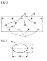
- Fig. 2 shows a plan view of a partial section of the board, from which the annular body is manufactured.
- the illustrated board 16 is in the manufacture of the ring body. 3 initially provided with the openings 17 and 18.
- the openings 17 have in the Supervision the shape of ellipses.
- In the outer width range of the board 16 are circular openings 18 are provided with a diameter of about 5 mm. It is conceivable to perform the openings 18 also in the form of ellipses, with respect to on the simplest possible production in this latitude circular openings are sufficient. Instead of the openings in the form of ellipses are also openings in Shape of oblong holes conceivable. All openings are made using a laser cutting process generated. Subsequently, the metallic board 16 is bent into an open ring and then welded at the free ends. With a conventional roll-push method the board 16 is then transformed so that it has the ring body shape shown in FIG with the two vaults.
- Fig. 3 shows a plan view of an opening in the form of an ellipse 17 with the corresponding main axis 19 and minor axis 20.
Landscapes
- Engineering & Computer Science (AREA)
- Mechanical Engineering (AREA)
- Tires In General (AREA)
- Motorcycle And Bicycle Frame (AREA)
Abstract
Description
Die DE 197 07 090 A1 offenbart ein Fahrzeugrad mit einem innerhalb des Luftreifenhohlraumes auf der Felge abgestützten Notlaufstützkörper, der aus einem schalenförmigen Ringkörper gebildet wird. Der Notlaufstützkörper wird über ein oder mehrere Stützelemente auf der Felge abgestützt. Die Stützelemente gehen dabei in den schalenförmigen Ringkörper über und sind entweder ein Teil desselben oder bestehen aus einem im Vergleich zum schalenförmigen Ringkörper anderen Werkstoff.
- Fig. 1
- ein Fahrzeugrad mit erfindungsgemäßem Notlaufstützkörper als Radialschnitt,
- Fig. 2
- eine Aufsicht eines Teilausschnittes der Platine, aus der der Ringkörper gefertigt wird und
- Fig. 3
- eine Aufsicht auf eine Öffnung in Form einer Ellipse.
- 1
- Notlaufstützkörper
- 2a,2b
- Stützelemente
- 3
- Ringkörper
- 4
- radiale Einschnürung des Ringkörpers
- 5,6
- nach radial außen gekrümmte Wölbungen des Ringkörpers
- 7
- axiale Mittelachse
- 8
- Reifenhohlraum
- 9
- Luftreifen
- 10
- Fahrzeugfelge
- 11
- Position der Öffnungen im linken Bereich des Ringkörpers
- 12
- Position der Öffnungen im rechten Bereich des Ringkörpers
- 13,14
- Position der Öffnungen im mittleren Bereich des Ringkörpers
- 15
- Hohlraum des Notlaufstützkörpers
- 16
- Platine
- 17
- Öffnungen in Form von Ellipsen
- 18
- kreisförmige Öffnungen
- 19
- Hauptachse
- 20
- Nebenachse
Claims (8)
- Fahrzeugrad mit einem auf einer Radfelge (10) befestigten Luftreifen (8) und einem Notlaufstützkörper (1), der als schalenförmiger Ringkörper (3) ausgebildet ist und sich mit seinen beiden axial äußeren Randbereichen (4,5) über ringförmige Stützelemente (2a,2b) auf der Radfelge (10) abstützt,
dadurch gekennzeichnet, dass
der Ringkörper (3) Öffnungen in Form einer Ellipse (17) aufweist. - Fahrzeugrad nach Anspruch 1,
dadurch gekennzeichnet, dass
die Hauptachsen (19) der Öffnungen in Form einer Ellipse (17) im Wesentlichen in Umfangsrichtung des Notlaufstützkörpers (1) ausgerichtet sind. - Fahrzeugrad nach Anspruch 1 oder 2,
dadurch gekennzeichnet, dass
die Öffnungen in Form einer Ellipse (17) im innenliegenden Breitenbereich des Ringkörpers (3) angeordnet sind. - Fahrzeugrad nach einem der Ansprüche 1 bis 3,
dadurch gekennzeichnet, dass
im außenliegenden Breitenbereich des Ringkörpers (3) kreisförmige Öffnungen (18) angeordnet sind. - Fahrzeugrad nach einem der Ansprüche 1 bis 4,
dadurch gekennzeichnet, dass
die Länge der Hauptachse (19) der Öffnung in Form einer Ellipse (17) zwischen 5 und 20 mm beträgt. - Fahrzeugrad nach einem der Ansprüche 1 bis 5, dadurch gekennzeichnet, dass das Verhältnis von Hauptachse (19) zu Nebenachse (20) der Öffnung in Form einer Ellipse (17) zwischen 1,1 und 1,6 beträgt.
- Verfahren zur Herstellung eines Notlaufstützkörpers (1) für Fahrzeugräder in Form eines schalenförmigen Ringkörpers (3), mit folgenden Schritten,Bereitstellen einer rechteckigen Platine (16),Einbringen von Öffnungen in Form von Ellipsen (19) in die Platine (16),Rundbiegen der Platine (16) zu einem offenen Ring,Verbinden der freien Enden des offenen Ringes undUmformen des Ringes mit einem Drück-Roll-Verfahren zu einem schalenförmigen Ringkörper (3) mit Wölbungen.
- Notlaufstützkörper (1), der als schalenförmiger Ringkörper (3) ausgebildet ist und in seinen beiden axial äußeren Randbereichen (4,5) ringförmige Stützelemente (2a,2b) aufweist,
dadurch gekennzeichnet, dass
der Ringkörper (3) Öffnungen in Form einer Ellipse (17) aufweist.
Priority Applications (3)
| Application Number | Priority Date | Filing Date | Title |
|---|---|---|---|
| DE50307894T DE50307894D1 (de) | 2003-09-10 | 2003-09-10 | Fahrzeugrad mit einem Notlaufstützkörper |
| AT03020391T ATE369260T1 (de) | 2003-09-10 | 2003-09-10 | Fahrzeugrad mit einem notlaufstützkörper |
| EP03020391A EP1514702B1 (de) | 2003-09-10 | 2003-09-10 | Fahrzeugrad mit einem Notlaufstützkörper |
Applications Claiming Priority (1)
| Application Number | Priority Date | Filing Date | Title |
|---|---|---|---|
| EP03020391A EP1514702B1 (de) | 2003-09-10 | 2003-09-10 | Fahrzeugrad mit einem Notlaufstützkörper |
Publications (2)
| Publication Number | Publication Date |
|---|---|
| EP1514702A1 true EP1514702A1 (de) | 2005-03-16 |
| EP1514702B1 EP1514702B1 (de) | 2007-08-08 |
Family
ID=34130170
Family Applications (1)
| Application Number | Title | Priority Date | Filing Date |
|---|---|---|---|
| EP03020391A Expired - Lifetime EP1514702B1 (de) | 2003-09-10 | 2003-09-10 | Fahrzeugrad mit einem Notlaufstützkörper |
Country Status (3)
| Country | Link |
|---|---|
| EP (1) | EP1514702B1 (de) |
| AT (1) | ATE369260T1 (de) |
| DE (1) | DE50307894D1 (de) |
Citations (5)
| Publication number | Priority date | Publication date | Assignee | Title |
|---|---|---|---|---|
| DE637158C (de) * | 1935-11-22 | 1936-10-23 | Hellmut Schultz | Gummischlauch fuer Fahrzeuge mit im Innern des Schlauches angeordneten Stuetzkoerpern |
| US4106543A (en) * | 1975-10-04 | 1978-08-15 | Honda Giken Kogyo Kabushiki Kaisha | Structure of sealing air valves for split rim type wheels |
| EP0508541A2 (de) * | 1991-04-11 | 1992-10-14 | Philips Patentverwaltung GmbH | Verfahren zum Herstellen eines ring- oder bogenförmigen Metallteils |
| DE4207781A1 (de) * | 1992-03-12 | 1993-09-23 | Berg Hans Gmbh & Co Kg | Verfahren zur herstellung eines stuetzrings |
| DE10208613C1 (de) * | 2002-02-27 | 2003-06-18 | Continental Ag | Fahrzeugrad mit einem Notlaufstützkörper |
-
2003
- 2003-09-10 DE DE50307894T patent/DE50307894D1/de not_active Expired - Fee Related
- 2003-09-10 AT AT03020391T patent/ATE369260T1/de not_active IP Right Cessation
- 2003-09-10 EP EP03020391A patent/EP1514702B1/de not_active Expired - Lifetime
Patent Citations (5)
| Publication number | Priority date | Publication date | Assignee | Title |
|---|---|---|---|---|
| DE637158C (de) * | 1935-11-22 | 1936-10-23 | Hellmut Schultz | Gummischlauch fuer Fahrzeuge mit im Innern des Schlauches angeordneten Stuetzkoerpern |
| US4106543A (en) * | 1975-10-04 | 1978-08-15 | Honda Giken Kogyo Kabushiki Kaisha | Structure of sealing air valves for split rim type wheels |
| EP0508541A2 (de) * | 1991-04-11 | 1992-10-14 | Philips Patentverwaltung GmbH | Verfahren zum Herstellen eines ring- oder bogenförmigen Metallteils |
| DE4207781A1 (de) * | 1992-03-12 | 1993-09-23 | Berg Hans Gmbh & Co Kg | Verfahren zur herstellung eines stuetzrings |
| DE10208613C1 (de) * | 2002-02-27 | 2003-06-18 | Continental Ag | Fahrzeugrad mit einem Notlaufstützkörper |
Also Published As
| Publication number | Publication date |
|---|---|
| DE50307894D1 (de) | 2007-09-20 |
| ATE369260T1 (de) | 2007-08-15 |
| EP1514702B1 (de) | 2007-08-08 |
Similar Documents
| Publication | Publication Date | Title |
|---|---|---|
| DE69315164T2 (de) | Luftreifen | |
| EP1023192A2 (de) | Fahrzeugrad mit einem notlaufstützkörper | |
| EP0143394A2 (de) | Speichenrad | |
| DE3711696A1 (de) | Wulstkern fuer einen fahrzeugluftreifen | |
| DE2649814A1 (de) | Reifen-felgen-anordnung und verfahren zu ihrer herstellung | |
| DE69805277T2 (de) | Notlaufvorrichtung für auto und verfahren zu seiner montage | |
| DE10304853A1 (de) | Verfahren zur Produktion einer Leichtmetallfelge für Automobile | |
| DE69820577T2 (de) | Rad mit Reifen und Komponenten | |
| DE2909057A1 (de) | Sicherheitstraeger fuer radfelgen | |
| DE10208613C1 (de) | Fahrzeugrad mit einem Notlaufstützkörper | |
| DE112004000169T5 (de) | Reifen-/Rad-Anordnung und Plattlaufstützelement | |
| EP2253486A1 (de) | Sicherheitsrad (varianten) | |
| DE2825394A1 (de) | Stuetzring fuer luftreifen | |
| DE10161365A1 (de) | Fahrzeugrad mit einem Notlaufstützkörper | |
| EP1514702B1 (de) | Fahrzeugrad mit einem Notlaufstützkörper | |
| DE102009017920A1 (de) | Gassackanordnung für ein Fahrzeuginsassen-Rückhaltesystem und Verfahren zum Herstellen einer Gassackanordnung | |
| DE60010332T2 (de) | An einer felge montierbare vorrichtung mit zentriermittel | |
| WO2006048155A1 (de) | Spurverstellrad und verfahren zur herstellung eines spurverstellrads | |
| EP1344657B1 (de) | Fahrzeugrad mit einem Notlaufstützkörper | |
| DE102004051482A1 (de) | Fahrzeugrad mit einem Notlaufstützkörper | |
| DE102004013517A1 (de) | Fahrzeugrad mit einem Notlaufstützkörper | |
| EP1740398B1 (de) | Fahrzeugluftreifen mit mehrteiligem kernprofil und verfahren zu dessen herstellung | |
| EP0153295B1 (de) | Luftbereiftes Fahrzeugrad | |
| DE10326341A1 (de) | Fahrzeugrad mit einem Notlaufstützkörper | |
| DE102004038950A1 (de) | Fahrzeugrad mit einem Notlaufstützkörper |
Legal Events
| Date | Code | Title | Description |
|---|---|---|---|
| PUAI | Public reference made under article 153(3) epc to a published international application that has entered the european phase |
Free format text: ORIGINAL CODE: 0009012 |
|
| AK | Designated contracting states |
Kind code of ref document: A1 Designated state(s): AT BE BG CH CY CZ DE DK EE ES FI FR GB GR HU IE IT LI LU MC NL PT RO SE SI SK TR |
|
| AX | Request for extension of the european patent |
Extension state: AL LT LV MK |
|
| 17P | Request for examination filed |
Effective date: 20050916 |
|
| AKX | Designation fees paid |
Designated state(s): AT BE BG CH CY CZ DE DK EE ES FI FR GB GR HU IE IT LI LU MC NL PT RO SE SI SK TR |
|
| GRAP | Despatch of communication of intention to grant a patent |
Free format text: ORIGINAL CODE: EPIDOSNIGR1 |
|
| GRAS | Grant fee paid |
Free format text: ORIGINAL CODE: EPIDOSNIGR3 |
|
| GRAA | (expected) grant |
Free format text: ORIGINAL CODE: 0009210 |
|
| AK | Designated contracting states |
Kind code of ref document: B1 Designated state(s): AT BE BG CH CY CZ DE DK EE ES FI FR GB GR HU IE IT LI LU MC NL PT RO SE SI SK TR |
|
| REG | Reference to a national code |
Ref country code: GB Ref legal event code: FG4D Free format text: NOT ENGLISH |
|
| PGFP | Annual fee paid to national office [announced via postgrant information from national office to epo] |
Ref country code: DE Payment date: 20070824 Year of fee payment: 5 |
|
| REG | Reference to a national code |
Ref country code: CH Ref legal event code: EP |
|
| REG | Reference to a national code |
Ref country code: IE Ref legal event code: FG4D Free format text: LANGUAGE OF EP DOCUMENT: GERMAN |
|
| REF | Corresponds to: |
Ref document number: 50307894 Country of ref document: DE Date of ref document: 20070920 Kind code of ref document: P |
|
| PG25 | Lapsed in a contracting state [announced via postgrant information from national office to epo] |
Ref country code: BG Free format text: LAPSE BECAUSE OF FAILURE TO SUBMIT A TRANSLATION OF THE DESCRIPTION OR TO PAY THE FEE WITHIN THE PRESCRIBED TIME-LIMIT Effective date: 20071108 Ref country code: ES Free format text: LAPSE BECAUSE OF FAILURE TO SUBMIT A TRANSLATION OF THE DESCRIPTION OR TO PAY THE FEE WITHIN THE PRESCRIBED TIME-LIMIT Effective date: 20071119 Ref country code: NL Free format text: LAPSE BECAUSE OF FAILURE TO SUBMIT A TRANSLATION OF THE DESCRIPTION OR TO PAY THE FEE WITHIN THE PRESCRIBED TIME-LIMIT Effective date: 20070808 Ref country code: FI Free format text: LAPSE BECAUSE OF FAILURE TO SUBMIT A TRANSLATION OF THE DESCRIPTION OR TO PAY THE FEE WITHIN THE PRESCRIBED TIME-LIMIT Effective date: 20070808 |
|
| NLV1 | Nl: lapsed or annulled due to failure to fulfill the requirements of art. 29p and 29m of the patents act | ||
| GBV | Gb: ep patent (uk) treated as always having been void in accordance with gb section 77(7)/1977 [no translation filed] |
Effective date: 20070808 |
|
| BERE | Be: lapsed |
Owner name: CONTINENTAL A.G. Effective date: 20070930 |
|
| REG | Reference to a national code |
Ref country code: IE Ref legal event code: FD4D |
|
| EN | Fr: translation not filed | ||
| PG25 | Lapsed in a contracting state [announced via postgrant information from national office to epo] |
Ref country code: MC Free format text: LAPSE BECAUSE OF NON-PAYMENT OF DUE FEES Effective date: 20070930 Ref country code: GR Free format text: LAPSE BECAUSE OF FAILURE TO SUBMIT A TRANSLATION OF THE DESCRIPTION OR TO PAY THE FEE WITHIN THE PRESCRIBED TIME-LIMIT Effective date: 20071109 Ref country code: DK Free format text: LAPSE BECAUSE OF FAILURE TO SUBMIT A TRANSLATION OF THE DESCRIPTION OR TO PAY THE FEE WITHIN THE PRESCRIBED TIME-LIMIT Effective date: 20070808 |
|
| REG | Reference to a national code |
Ref country code: CH Ref legal event code: PL |
|
| PG25 | Lapsed in a contracting state [announced via postgrant information from national office to epo] |
Ref country code: IE Free format text: LAPSE BECAUSE OF FAILURE TO SUBMIT A TRANSLATION OF THE DESCRIPTION OR TO PAY THE FEE WITHIN THE PRESCRIBED TIME-LIMIT Effective date: 20070808 Ref country code: SK Free format text: LAPSE BECAUSE OF FAILURE TO SUBMIT A TRANSLATION OF THE DESCRIPTION OR TO PAY THE FEE WITHIN THE PRESCRIBED TIME-LIMIT Effective date: 20070808 Ref country code: GB Free format text: LAPSE BECAUSE OF FAILURE TO SUBMIT A TRANSLATION OF THE DESCRIPTION OR TO PAY THE FEE WITHIN THE PRESCRIBED TIME-LIMIT Effective date: 20070808 Ref country code: CZ Free format text: LAPSE BECAUSE OF FAILURE TO SUBMIT A TRANSLATION OF THE DESCRIPTION OR TO PAY THE FEE WITHIN THE PRESCRIBED TIME-LIMIT Effective date: 20070808 Ref country code: PT Free format text: LAPSE BECAUSE OF FAILURE TO SUBMIT A TRANSLATION OF THE DESCRIPTION OR TO PAY THE FEE WITHIN THE PRESCRIBED TIME-LIMIT Effective date: 20080108 |
|
| PLBE | No opposition filed within time limit |
Free format text: ORIGINAL CODE: 0009261 |
|
| STAA | Information on the status of an ep patent application or granted ep patent |
Free format text: STATUS: NO OPPOSITION FILED WITHIN TIME LIMIT |
|
| PG25 | Lapsed in a contracting state [announced via postgrant information from national office to epo] |
Ref country code: SE Free format text: LAPSE BECAUSE OF FAILURE TO SUBMIT A TRANSLATION OF THE DESCRIPTION OR TO PAY THE FEE WITHIN THE PRESCRIBED TIME-LIMIT Effective date: 20071108 Ref country code: RO Free format text: LAPSE BECAUSE OF FAILURE TO SUBMIT A TRANSLATION OF THE DESCRIPTION OR TO PAY THE FEE WITHIN THE PRESCRIBED TIME-LIMIT Effective date: 20070808 |
|
| 26N | No opposition filed |
Effective date: 20080509 |
|
| PG25 | Lapsed in a contracting state [announced via postgrant information from national office to epo] |
Ref country code: CH Free format text: LAPSE BECAUSE OF NON-PAYMENT OF DUE FEES Effective date: 20070930 Ref country code: LI Free format text: LAPSE BECAUSE OF NON-PAYMENT OF DUE FEES Effective date: 20070930 |
|
| PG25 | Lapsed in a contracting state [announced via postgrant information from national office to epo] |
Ref country code: BE Free format text: LAPSE BECAUSE OF NON-PAYMENT OF DUE FEES Effective date: 20070930 |
|
| PG25 | Lapsed in a contracting state [announced via postgrant information from national office to epo] |
Ref country code: AT Free format text: LAPSE BECAUSE OF NON-PAYMENT OF DUE FEES Effective date: 20070910 |
|
| PG25 | Lapsed in a contracting state [announced via postgrant information from national office to epo] |
Ref country code: EE Free format text: LAPSE BECAUSE OF FAILURE TO SUBMIT A TRANSLATION OF THE DESCRIPTION OR TO PAY THE FEE WITHIN THE PRESCRIBED TIME-LIMIT Effective date: 20070808 |
|
| PG25 | Lapsed in a contracting state [announced via postgrant information from national office to epo] |
Ref country code: FR Free format text: LAPSE BECAUSE OF NON-PAYMENT OF DUE FEES Effective date: 20070930 |
|
| PG25 | Lapsed in a contracting state [announced via postgrant information from national office to epo] |
Ref country code: SI Free format text: LAPSE BECAUSE OF FAILURE TO SUBMIT A TRANSLATION OF THE DESCRIPTION OR TO PAY THE FEE WITHIN THE PRESCRIBED TIME-LIMIT Effective date: 20070808 |
|
| PG25 | Lapsed in a contracting state [announced via postgrant information from national office to epo] |
Ref country code: CY Free format text: LAPSE BECAUSE OF FAILURE TO SUBMIT A TRANSLATION OF THE DESCRIPTION OR TO PAY THE FEE WITHIN THE PRESCRIBED TIME-LIMIT Effective date: 20070808 |
|
| PG25 | Lapsed in a contracting state [announced via postgrant information from national office to epo] |
Ref country code: DE Free format text: LAPSE BECAUSE OF NON-PAYMENT OF DUE FEES Effective date: 20090401 Ref country code: LU Free format text: LAPSE BECAUSE OF NON-PAYMENT OF DUE FEES Effective date: 20070910 |
|
| PG25 | Lapsed in a contracting state [announced via postgrant information from national office to epo] |
Ref country code: HU Free format text: LAPSE BECAUSE OF FAILURE TO SUBMIT A TRANSLATION OF THE DESCRIPTION OR TO PAY THE FEE WITHIN THE PRESCRIBED TIME-LIMIT Effective date: 20080209 Ref country code: TR Free format text: LAPSE BECAUSE OF FAILURE TO SUBMIT A TRANSLATION OF THE DESCRIPTION OR TO PAY THE FEE WITHIN THE PRESCRIBED TIME-LIMIT Effective date: 20070808 |
|
| PG25 | Lapsed in a contracting state [announced via postgrant information from national office to epo] |
Ref country code: IT Free format text: LAPSE BECAUSE OF NON-PAYMENT OF DUE FEES Effective date: 20070930 |