EP1514702B1 - Fahrzeugrad mit einem Notlaufstützkörper - Google Patents
Fahrzeugrad mit einem Notlaufstützkörper Download PDFInfo
- Publication number
- EP1514702B1 EP1514702B1 EP03020391A EP03020391A EP1514702B1 EP 1514702 B1 EP1514702 B1 EP 1514702B1 EP 03020391 A EP03020391 A EP 03020391A EP 03020391 A EP03020391 A EP 03020391A EP 1514702 B1 EP1514702 B1 EP 1514702B1
- Authority
- EP
- European Patent Office
- Prior art keywords
- openings
- vehicle wheel
- support body
- annular body
- support
- Prior art date
- Legal status (The legal status is an assumption and is not a legal conclusion. Google has not performed a legal analysis and makes no representation as to the accuracy of the status listed.)
- Expired - Lifetime
Links
- 230000002093 peripheral effect Effects 0.000 claims 1
- 238000000034 method Methods 0.000 abstract description 4
- 238000005452 bending Methods 0.000 abstract 1
- 238000004519 manufacturing process Methods 0.000 description 6
- 230000015556 catabolic process Effects 0.000 description 5
- 230000037237 body shape Effects 0.000 description 1
- 230000006378 damage Effects 0.000 description 1
- 238000009826 distribution Methods 0.000 description 1
- 238000003698 laser cutting Methods 0.000 description 1
- BASFCYQUMIYNBI-UHFFFAOYSA-N platinum Chemical compound [Pt] BASFCYQUMIYNBI-UHFFFAOYSA-N 0.000 description 1
Images

Classifications
-
- B—PERFORMING OPERATIONS; TRANSPORTING
- B60—VEHICLES IN GENERAL
- B60C—VEHICLE TYRES; TYRE INFLATION; TYRE CHANGING; CONNECTING VALVES TO INFLATABLE ELASTIC BODIES IN GENERAL; DEVICES OR ARRANGEMENTS RELATED TO TYRES
- B60C17/00—Tyres characterised by means enabling restricted operation in damaged or deflated condition; Accessories therefor
- B60C17/04—Tyres characterised by means enabling restricted operation in damaged or deflated condition; Accessories therefor utilising additional non-inflatable supports which become load-supporting in emergency
- B60C17/06—Tyres characterised by means enabling restricted operation in damaged or deflated condition; Accessories therefor utilising additional non-inflatable supports which become load-supporting in emergency resilient
-
- B—PERFORMING OPERATIONS; TRANSPORTING
- B21—MECHANICAL METAL-WORKING WITHOUT ESSENTIALLY REMOVING MATERIAL; PUNCHING METAL
- B21D—WORKING OR PROCESSING OF SHEET METAL OR METAL TUBES, RODS OR PROFILES WITHOUT ESSENTIALLY REMOVING MATERIAL; PUNCHING METAL
- B21D53/00—Making other particular articles
- B21D53/16—Making other particular articles rings, e.g. barrel hoops
Definitions
- the invention relates to a vehicle with a wheel rim mounted on a pneumatic tire and a Notlaufstütz redesign, which is designed as a cup-shaped annular body and is supported with its two axially outer edge regions via annular support elements on the wheel rim.
- a major disadvantage of tubeless pneumatic tires is the possible occurrence of a leak, causing the tire to lose air pressure and collapse the tire.
- the sudden escape of the air in the tire can lead to dangerous situations in which the driver loses control of his vehicle.
- the tire can be damaged in a pressure loss that the vehicle rim cuts into the inner core and overlying layers.
- the DE 197 07 090 A1 discloses a vehicle wheel having a run-flat support body supported on the rim within the pneumatic tire cavity and formed of a cup-shaped ring body.
- the runflat support body is supported by one or more support elements on the rim.
- the support elements go over into the cup-shaped annular body and are either part of the same or consist of a different material compared to the cup-shaped annular body.
- a disadvantage of the emergency running support bodies is that the filling of a tire with an emergency running support body takes a relatively long time, since the compressed air has to pass from the cavity of the emergency running support body into the cavity between the emergency running support body and the inside of the tire. It should be noted that the emergency support body has to absorb a high load in the event of a breakdown and the strength of the emergency running support body may not be reduced.
- the invention is based on the object to provide an emergency running support for a pneumatic tire, which allows a quick filling of the pneumatic tire with compressed air and at the same time does not significantly affect the strength properties of the emergency running support.
- the emergency running support body allows a quick filling of the pneumatic tire with compressed air and at the same time the strength properties of the emergency running support are substantially maintained.
- the openings in the form of ellipses can optimally absorb the stresses occurring in the event of a breakdown and thereby give the emergency running support body a high fatigue strength.
- the main axes of the openings are aligned in the form of an ellipse substantially in the circumferential direction of the emergency running support body.
- the greatest strains occur in the circumferential direction of the ring body.
- the alignment of the main axis of the ellipse in the circumferential direction of the ring body results in the forming process an optimal stress distribution in the bearing.
- the openings are arranged in the form of an ellipse in the inner width region of the annular body.
- the internal width region is exposed to a particularly high stress, which is why the openings in the form of an ellipse are preferably arranged in this region.
- the length of the main axis of the opening in the form of an ellipse is between 5 and 20 mm. This length range is to be regarded as optimal in terms of the lowest possible strength reduction.
- the ratio of the main axis to the minor axis of the opening in the form of an ellipse is between 1.1 and 1.6. Such ellipse ratio can be easily realized for manufacturing reasons.
- FIG. 1 shows a vehicle wheel with emergency running support 1 according to the invention as a radial section.
- the emergency running support body 1 which is rotationally symmetrical, is arranged in the tire cavity 8 of the pneumatic tire 9 and is supported on the two annular support elements 2a and 2b on a conventional vehicle rim 10.
- the emergency running support body 1 consists essentially of the two support elements 2a and 2b and the cup-shaped annular body 3.
- the openings in the annular body are located at the positions 11, 12, 13 and 14. At the positions 11 and 12 are successively in the circumferential direction of the annular body each circular Openings in the outer width region of the annular body 3.
- openings in the form of ellipses in the positions 13 and 14 are distributed over the circumference of the annular body.
- the positions 13 and 14 are arranged in the inner width region. The openings allow for optimal and rapid air exchange between the tire cavity 8 and the cavity 15 of the Notlaufstütz stressess.
- the openings in the form of ellipses have the advantage that the strength of the annular body is not significantly reduced for the breakdown case.
- the pneumatic tire is supported directly on the emergency support body, whereby a high mechanical stress of the annular body takes place.
- stress peaks could occur due to the compressive stress, which initially lead to small cracks and finally to the destruction of the emergency running support.
- the openings in the form of Ellipses have the decisive advantage that the emergency running support with these openings can absorb a higher load in the event of a breakdown than is the case with ordinary circular openings.
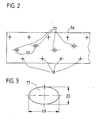
- Fig. 2 shows a plan view of a partial section of the board from which the ring body is made.
- the illustrated board 16 is initially provided with the openings 17 and 18 in the manufacture of the ring body 3.
- the openings 17 have the shape of ellipses in the plan view.
- circular openings 18 are provided with a diameter of about 5 mm. It is also conceivable to design the openings 18 in the form of ellipses, with circular openings being sufficient in view of the simplest possible production in this width range. Instead of the openings in the form of ellipses openings in the form of slots are also conceivable. All openings are created by a laser cutting process.
- the metallic board 16 is bent into an open ring and then welded at the free ends. With a conventional roll-push method, the board 16 is then transformed so that it receives the ring body shape shown in Fig. 1 with the two vaults.
- FIG. 3 shows a plan view of an opening in the form of an ellipse 17 with the corresponding main axis 19 and minor axis 20.
Landscapes
- Engineering & Computer Science (AREA)
- Mechanical Engineering (AREA)
- Tires In General (AREA)
- Motorcycle And Bicycle Frame (AREA)
Description
- Die Erfindung betrifft ein Fahrzeugrad mit einem auf einer Radfelge befestigten Luftreifen und einem Notlaufstützkörper, der als schalenförmiger Ringkörper ausgebildet ist und sich mit seinen beiden axial äußeren Randbereichen über ringförmige Stützelemente auf der Radfelge abstützt.
- Ein wesentlicher Nachteil von schlauchlosen Luftreifen ist das mögliche Auftreten einer Undichtigkeit, wodurch der Luftdruck im Reifen abfällt und der Reifen kollabiert. Bei einer hohen Fahrzeuggeschwindigkeit kann das plötzliche Entweichen der Luft im Reifen zu gefährlichen Situationen führen, in denen der Fahrer die Kontrolle über sein Fahrzeug verliert. Ferner kann der Reifen bei einem Druckverlust dadurch beschädigt werden, dass die Fahrzeugfelge sich in die Innenseele und darüber liegende Lagen einschneidet.
- Für Luftreifen sind verschiedene Notlaufstützkörper-Systeme bekannt.
DieDE 197 07 090 A1 offenbart ein Fahrzeugrad mit einem innerhalb des Luftreifenhohlraumes auf der Felge abgestützten Notlaufstützkörper, der aus einem schalenförmigen Ringkörper gebildet wird. Der Notlaufstützkörper wird über ein oder mehrere Stützelemente auf der Felge abgestützt. Die Stützelemente gehen dabei in den schalenförmigen Ringkörper über und sind entweder ein Teil desselben oder bestehen aus einem im Vergleich zum schalenförmigen Ringkörper anderen Werkstoff. - In der
DE 198 25 311 C1 ist ein anderes Notlaufstützkörpersystem offenbart, bei dem ein schalenförmiger Ringkörper innerhalb des Luftreifenhohlraumes angeordnet ist. Die beiden axial äußeren Randbereiche des Notlaufstützkörpers stützen sich über zwei elastische ringförmige Stützelemente auf der Felge ab. Die Stützelemente besitzen in radialer sowie axialer Richtung unterschiedliche Elastizitätskennwerte und sind mit dem metallischen Notlaufstützkörper stoffschlüssig verbunden. Der Notlaufstützkörper ist ferner als geschlitzter Ringkörper mit einem in axialer Richtung verlaufenden Öffnungsschlitz ausgebildet, wodurch die Montage auf die Felge ermöglicht wird. Der Notlaufstützkörper wird im Bereich des Öffnungsschlitzes auseinandergezogen und anschließend in den Reifenhohlraum hineingedreht. Der Öffnungsschlitz wird danach über einen oder mehrere Flansche verbunden. - Ein Nachteil der Notlaufstützkörper besteht darin, dass das Befüllen eines Reifens mit einem Notlaufstützkörper eine relativ lange Zeit in Anspruch nimmt, da die Druckluft vom Hohlraum des Notlaufstützkörpers in den Hohlraum zwischen Notlaufstützkörper und Reifeninnenseite gelangen muss. Dabei ist zu berücksichtigen, dass der Notlaufstützkörper im Pannenfall eine hohe Last aufzunehmen hat und die Festigkeit des Notlaufstützkörpers nicht herabgesetzt werden darf.
- Der Erfindung liegt die Aufgabe zu Grunde, einen Notlaufstützkörper für einen Luftreifen zu schaffen, der ein schnelles Befüllen des Luftreifens mit Druckluft ermöglicht und gleichzeitig nicht wesentlich die Festigkeitseigenschaften des Notlaufstützkörpers beeinträchtigt.
- Gelöst wird die Aufgabe gemäß den kennzeichnenden Merkmalen des Anspruchs 1.
- Ein Vorteil ist insbesondere darin zu sehen, dass der Notlaufstützkörper ein schnelles Befüllen des Luftreifens mit Druckluft ermöglicht und gleichzeitig die Festigkeitseigenschaften des Notlaufstützkörpers im Wesentlichen beibehalten werden. Die Öffnungen in Form von Ellipsen können die auftretenden Beanspruchungen im Pannenfall optimal aufnehmen und verleihen dem Notlaufstützkörper dadurch eine hohe Dauerfestigkeit.
- In einer vorteilhaften Weiterbildung der Erfindung ist vorgesehen, dass die Hauptachsen der Öffnungen in Form einer Ellipse im Wesentlichen in Umfangsrichtung des Notlaufstützkörpers ausgerichtet sind. Bei der Herstellung des Ringkörpers treten die größten Dehnungen in Umfangsrichtung des Ringkörpers auf. Die Ausrichtung der Hauptachse der Ellipse in Umfangsrichtung des Ringkörpers ergibt beim Umformprozeß eine optimale Spannungsverteilung in der Lochleibung.
- In einer weiteren vorteilhaften Weiterbildung der Erfindung ist vorgesehen, dass die Öffnungen in Form einer Ellipse im innenliegenden Breitenbereich des Ringkörpers angeordnet sind. Bei der Herstellung des Ringkörpers ist der innenliegende Breitenbereich einer besonders hohen Beanspruchung ausgesetzt, weshalb die Öffnungen in Form einer Ellipse vorzugsweise in diesem Bereich angeordnet sind.
- In einer weiteren vorteilhaften Weiterbildung der Erfindung ist vorgesehen, dass im außenliegenden Breitenbereich des Ringkörpers kreisförmige Öffnungen angeordnet sind. Im außenliegenden Breitenbereich des Ringkörpers sind die auftretenden Beanspruchungen geringer. Aus fertigungstechnischen Gründen ist es daher vorteilhaft, in diesem Bereich kreisförmige Öffnungen vorzusehen.
- In einer weiteren vorteilhaften Weiterbildung der Erfindung ist vorgesehen, dass die Länge der Hauptachse der Öffnung in Form einer Ellipse zwischen 5 und 20 mm beträgt. Dieser Längenbereich ist im Hinblick auf eine möglichst geringe Festigkeitsreduzierung als optimal anzusehen.
- In einer weiteren vorteilhaften Weiterbildung der Erfindung ist vorgesehen, dass das Verhältnis von Hauptachse zu Nebenachse der Öffnung in Form einer Ellipse zwischen 1,1 und 1,6 beträgt. Ein solches Ellipsenverhältnis lässt sich aus fertigungstechnischen Gründen einfach realisieren.
- Anhand eines Ausführungsbeispiels soll die Erfindung näher erläutert werden. Es zeigen:
- Fig. 1
- ein Fahrzeugrad mit erfindungsgemäßem Notlaufstützkörper als Radialschnitt,
- Fig. 2
- eine Aufsicht eines Teilausschnittes der Platine, aus der der Ringkörper gefertigt wird und
- Fig. 3
- eine Aufsicht auf eine Öffnung in Form einer Ellipse.
- Figur 1 zeigt ein Fahrzeugrad mit erfindungsgemäßem Notlaufstützkörper 1 als Radialschnitt. Der Notlaufstützkörper 1, der rotationssymetrisch ist, ist im Reifenhohlraum 8 des Luftreifens 9 angeordnet und stützt sich über die beiden ringförmigen Stützelemente 2a und 2b auf einer herkömmlichen Fahrzeugfelge 10 ab. Der Notlaufstützkörper 1 besteht im Wesentlichen aus den beiden Stützelementen 2a und 2b sowie dem schalenförmigen Ringkörper 3. Die Öffnungen im Ringkörper befinden sich an den Positionen 11, 12, 13 und 14. An den Positionen 11 und 12 liegen hintereinander in Umfangsrichtung des Ringkörpers jeweils kreisförmige Öffnungen im außenliegenden Breitenbereich des Ringkörpers 3. Im Bereich der radialen Einschnürung 4 sind auf den Umfang des Ringkörpers verteilt jeweils Öffnungen in Form von Ellipsen in den Positionen 13 und 14 angeordnet. Die Positionen 13 und 14 sind im innenliegenden Breitenbereich angeordnet. Die Öffnungen ermöglichen einen optimalen und schnellen Luftaustausch zwischen dem Reifenhohlraum 8 und dem Hohlraum 15 des Notlaufstützkörpers.
- Die Öffnungen in Form von Ellipsen besitzen den Vorteil, dass die Festigkeit des Ringkörpers für den Pannenfall nicht wesentlich reduziert wird. Im Pannenfall stützt sich der Luftreifen direkt auf den Notlaufstützkörper ab, wodurch eine hohe mechanische Beanspruchung des Ringkörpers erfolgt. An den Öffnungen im Ringkörper könnten durch die Druckbeanspruchung Spannungsspitzen auftreten, die zunächst zu kleinen Rissen und schließlich zur Zerstörung des Notlaufstützkörpers führen. Die Öffnungen in Form von Ellipsen besitzen den entscheidenden Vorteil, dass der Notlaufstützkörper mit diesen Öffnungen im Pannenfall eine höhere Last aufnehmen kann als das bei gewöhnlichen kreisförmigen Öffnungen der Fall ist.
- Fig. 2 zeigt eine Aufsicht eines Teilausschnittes der Platine, aus der der Ringkörper gefertigt wird. Die dargestellte Platine 16 wird bei der Herstellung des Ringkörpers 3 zunächst mit den Öffnungen 17 und 18 versehen. Die Öffnungen 17 besitzen in der Aufsicht die Form von Ellipsen. Im außenliegenden Breitenbereich der Platine 16 sind kreisförmige Öffnungen 18 mit einem Durchmesser von etwa 5 mm vorgesehen. Es ist denkbar, die Öffnungen 18 ebenfalls in Form von Ellipsen auszuführen, wobei im Hinblick auf eine möglichst einfache Fertigung in diesem Breitenbereich kreisrunde Öffnungen ausreichend sind. Statt der Öffnungen in Form von Ellipsen sind ebenfalls Öffnungen in Form von Langlöchern denkbar. Alle Öffnungen werden mit einem Laserschneidverfahren erzeugt. Anschließend wird die metallische Platine 16 zu einem offenen Ring gebogen und sodann an den freien Enden verschweißt. Mit einem herkömmlichen Roll-Drück-Verfahren wird die Platine 16 dann so umgeformt, dass sie die in Fig. 1 dargestellte Ringkörperform mit den zwei Wölbungen erhält.
- Fig. 3 zeigt eine Aufsicht auf eine Öffnung in Form einer Ellipse 17 mit der entsprechenden Hauptachse 19 und Nebenachse 20.
-
- 1
- Notlaufstützkörper
- 2a,2b
- Stützelemente
- 3
- Ringkörper
- 4
- radiale Einschnürung des Ringkörpers
- 5,6
- nach radial außen gekrümmte Wölbungen des Ringkörpers
- 7
- axiale Mittelachse
- 8
- Reifenhohlraum
- 9
- Luftreifen
- 10
- Fahrzeugfelge
- 11
- Position der Öffnungen im linken Bereich des Ringkörpers
- 12
- Position der Öffnungen im rechten Bereich des Ringkörpers
- 13,14
- Position der Öffnungen im mittleren Bereich des Ringkörpers
- 15
- Hohlraum des Notlaufstützkörpers
- 16
- Platine
- 17
- Öffnungen in Form von Ellipsen
- 18
- kreisförmige Öffnungen
- 19
- Hauptachse
- 20
- Nebenachse
Claims (5)
- Fahrzeugrad mit einem auf einer Radfelge (10) befestigten Luftreifen (8) und einem Notlaufstützkörper (1), der als schalenförmiger Ringkörper (3) ausgebildet ist und sich mit seinen beiden axial äußeren Randbereichen (4,5) über ringförmige Stützelemente (2a,2b) auf der Radfelge (10) abstützt,
dadurch gekennzeichnet, dass
der Ringkörper (3) Öffnungen in Form einer Ellipse (17) aufweist,
wobei die Öffnungen in Form einer Ellipse (17) im innenliegenden Breitenbereich des Ringkörpers (3) angeordnet sind. - Fahrzeugrad nach Anspruch 1,
dadurch gekennzeichnet, dass
die Hauptachsen (19) der Öffnungen in Form einer Ellipse (17) im Wesentlichen in Umfangsrichtung des Notlaufstützkörpers (1) ausgerichtet sind. - Fahrzeugrad nach Anspruch 1 oder 2,
dadurch gekennzeichnet, dass
im außenliegenden Breitenbereich des Ringkörpers (3) kreisförmige Öffnungen (18) angeordnet sind. - Fahrzeugrad nach einem der Ansprüche 1 bis 3,
dadurch gekennzeichnet, dass
die Länge der Hauptachse (19) der Öffnung in Form einer Ellipse (17) zwischen 5 und 20 mm beträgt. - Fahrzeugrad nach einem der Ansprüche 1 bis 4,
dadurch gekennzeichnet, dass
das Verhältnis von Hauptachse (19) zu Nebenachse (20) der Öffnung in Form einer Ellipse (17) zwischen 1,1 und 1,6 beträgt.
Priority Applications (3)
| Application Number | Priority Date | Filing Date | Title |
|---|---|---|---|
| DE50307894T DE50307894D1 (de) | 2003-09-10 | 2003-09-10 | Fahrzeugrad mit einem Notlaufstützkörper |
| EP03020391A EP1514702B1 (de) | 2003-09-10 | 2003-09-10 | Fahrzeugrad mit einem Notlaufstützkörper |
| AT03020391T ATE369260T1 (de) | 2003-09-10 | 2003-09-10 | Fahrzeugrad mit einem notlaufstützkörper |
Applications Claiming Priority (1)
| Application Number | Priority Date | Filing Date | Title |
|---|---|---|---|
| EP03020391A EP1514702B1 (de) | 2003-09-10 | 2003-09-10 | Fahrzeugrad mit einem Notlaufstützkörper |
Publications (2)
| Publication Number | Publication Date |
|---|---|
| EP1514702A1 EP1514702A1 (de) | 2005-03-16 |
| EP1514702B1 true EP1514702B1 (de) | 2007-08-08 |
Family
ID=34130170
Family Applications (1)
| Application Number | Title | Priority Date | Filing Date |
|---|---|---|---|
| EP03020391A Expired - Lifetime EP1514702B1 (de) | 2003-09-10 | 2003-09-10 | Fahrzeugrad mit einem Notlaufstützkörper |
Country Status (3)
| Country | Link |
|---|---|
| EP (1) | EP1514702B1 (de) |
| AT (1) | ATE369260T1 (de) |
| DE (1) | DE50307894D1 (de) |
Family Cites Families (5)
| Publication number | Priority date | Publication date | Assignee | Title |
|---|---|---|---|---|
| DE637158C (de) * | 1935-11-22 | 1936-10-23 | Hellmut Schultz | Gummischlauch fuer Fahrzeuge mit im Innern des Schlauches angeordneten Stuetzkoerpern |
| JPS5339922Y2 (de) * | 1975-10-04 | 1978-09-27 | ||
| DE4111780A1 (de) * | 1991-04-11 | 1992-10-15 | Philips Patentverwaltung | Verfahren zum herstellen eines ring- oder bogenfoermigen metallteils |
| DE4207781C2 (de) * | 1992-03-12 | 1996-12-19 | Berg Hans Gmbh & Co Kg | Verfahren zur Herstellung eines käfigartigen Stützrings für einen Flachheizkörper |
| DE10208613C1 (de) * | 2002-02-27 | 2003-06-18 | Continental Ag | Fahrzeugrad mit einem Notlaufstützkörper |
-
2003
- 2003-09-10 EP EP03020391A patent/EP1514702B1/de not_active Expired - Lifetime
- 2003-09-10 DE DE50307894T patent/DE50307894D1/de not_active Expired - Fee Related
- 2003-09-10 AT AT03020391T patent/ATE369260T1/de not_active IP Right Cessation
Also Published As
| Publication number | Publication date |
|---|---|
| DE50307894D1 (de) | 2007-09-20 |
| ATE369260T1 (de) | 2007-08-15 |
| EP1514702A1 (de) | 2005-03-16 |
Similar Documents
| Publication | Publication Date | Title |
|---|---|---|
| DE69315164T2 (de) | Luftreifen | |
| DE19745409C2 (de) | Fahrzeugrad mit einem Notlaufstützkörper | |
| DE10130291C2 (de) | Notlaufstützkörper | |
| WO1999064260A1 (de) | Fahrzeugrad mit einem notlaufstützkörper | |
| DE112013006211T5 (de) | Reifen-Rad-Baugruppe und Laufflächenring | |
| DE2649814A1 (de) | Reifen-felgen-anordnung und verfahren zu ihrer herstellung | |
| DE112004001432T5 (de) | Luftreifen | |
| DE10208613C1 (de) | Fahrzeugrad mit einem Notlaufstützkörper | |
| DE2909057A1 (de) | Sicherheitstraeger fuer radfelgen | |
| DE60300254T2 (de) | Notlaufstützring für einen Reifen | |
| DE112004000169T5 (de) | Reifen-/Rad-Anordnung und Plattlaufstützelement | |
| EP2253486A1 (de) | Sicherheitsrad (varianten) | |
| DE2825394A1 (de) | Stuetzring fuer luftreifen | |
| DE10161365A1 (de) | Fahrzeugrad mit einem Notlaufstützkörper | |
| DE102009017920A1 (de) | Gassackanordnung für ein Fahrzeuginsassen-Rückhaltesystem und Verfahren zum Herstellen einer Gassackanordnung | |
| EP1514702A1 (de) | Fahrzeugrad mit einem Notlaufstützkörper | |
| EP1344657B1 (de) | Fahrzeugrad mit einem Notlaufstützkörper | |
| DE102004051482A1 (de) | Fahrzeugrad mit einem Notlaufstützkörper | |
| DE10326341A1 (de) | Fahrzeugrad mit einem Notlaufstützkörper | |
| EP1811195B1 (de) | Gelenklager, insbesondere zur Lagerung von Achslenkern in Kraftfahrzeugen | |
| DE102004013517A1 (de) | Fahrzeugrad mit einem Notlaufstützkörper | |
| EP1449682B1 (de) | Fahrzeugrad mit einem Notlaufstützkörper | |
| DE102004044542A1 (de) | Fahrzeugrad mit einem Notlaufstützkörper | |
| EP1993853B1 (de) | Fahrzeugrad | |
| DE10138410B4 (de) | Notlaufstützkörper für luftbereiftes Fahrzeugrad |
Legal Events
| Date | Code | Title | Description |
|---|---|---|---|
| PUAI | Public reference made under article 153(3) epc to a published international application that has entered the european phase |
Free format text: ORIGINAL CODE: 0009012 |
|
| AK | Designated contracting states |
Kind code of ref document: A1 Designated state(s): AT BE BG CH CY CZ DE DK EE ES FI FR GB GR HU IE IT LI LU MC NL PT RO SE SI SK TR |
|
| AX | Request for extension of the european patent |
Extension state: AL LT LV MK |
|
| 17P | Request for examination filed |
Effective date: 20050916 |
|
| AKX | Designation fees paid |
Designated state(s): AT BE BG CH CY CZ DE DK EE ES FI FR GB GR HU IE IT LI LU MC NL PT RO SE SI SK TR |
|
| GRAP | Despatch of communication of intention to grant a patent |
Free format text: ORIGINAL CODE: EPIDOSNIGR1 |
|
| GRAS | Grant fee paid |
Free format text: ORIGINAL CODE: EPIDOSNIGR3 |
|
| GRAA | (expected) grant |
Free format text: ORIGINAL CODE: 0009210 |
|
| AK | Designated contracting states |
Kind code of ref document: B1 Designated state(s): AT BE BG CH CY CZ DE DK EE ES FI FR GB GR HU IE IT LI LU MC NL PT RO SE SI SK TR |
|
| REG | Reference to a national code |
Ref country code: GB Ref legal event code: FG4D Free format text: NOT ENGLISH |
|
| PGFP | Annual fee paid to national office [announced via postgrant information from national office to epo] |
Ref country code: DE Payment date: 20070824 Year of fee payment: 5 |
|
| REG | Reference to a national code |
Ref country code: CH Ref legal event code: EP |
|
| REG | Reference to a national code |
Ref country code: IE Ref legal event code: FG4D Free format text: LANGUAGE OF EP DOCUMENT: GERMAN |
|
| REF | Corresponds to: |
Ref document number: 50307894 Country of ref document: DE Date of ref document: 20070920 Kind code of ref document: P |
|
| PG25 | Lapsed in a contracting state [announced via postgrant information from national office to epo] |
Ref country code: BG Free format text: LAPSE BECAUSE OF FAILURE TO SUBMIT A TRANSLATION OF THE DESCRIPTION OR TO PAY THE FEE WITHIN THE PRESCRIBED TIME-LIMIT Effective date: 20071108 Ref country code: ES Free format text: LAPSE BECAUSE OF FAILURE TO SUBMIT A TRANSLATION OF THE DESCRIPTION OR TO PAY THE FEE WITHIN THE PRESCRIBED TIME-LIMIT Effective date: 20071119 Ref country code: NL Free format text: LAPSE BECAUSE OF FAILURE TO SUBMIT A TRANSLATION OF THE DESCRIPTION OR TO PAY THE FEE WITHIN THE PRESCRIBED TIME-LIMIT Effective date: 20070808 Ref country code: FI Free format text: LAPSE BECAUSE OF FAILURE TO SUBMIT A TRANSLATION OF THE DESCRIPTION OR TO PAY THE FEE WITHIN THE PRESCRIBED TIME-LIMIT Effective date: 20070808 |
|
| NLV1 | Nl: lapsed or annulled due to failure to fulfill the requirements of art. 29p and 29m of the patents act | ||
| GBV | Gb: ep patent (uk) treated as always having been void in accordance with gb section 77(7)/1977 [no translation filed] |
Effective date: 20070808 |
|
| BERE | Be: lapsed |
Owner name: CONTINENTAL A.G. Effective date: 20070930 |
|
| REG | Reference to a national code |
Ref country code: IE Ref legal event code: FD4D |
|
| EN | Fr: translation not filed | ||
| PG25 | Lapsed in a contracting state [announced via postgrant information from national office to epo] |
Ref country code: MC Free format text: LAPSE BECAUSE OF NON-PAYMENT OF DUE FEES Effective date: 20070930 Ref country code: GR Free format text: LAPSE BECAUSE OF FAILURE TO SUBMIT A TRANSLATION OF THE DESCRIPTION OR TO PAY THE FEE WITHIN THE PRESCRIBED TIME-LIMIT Effective date: 20071109 Ref country code: DK Free format text: LAPSE BECAUSE OF FAILURE TO SUBMIT A TRANSLATION OF THE DESCRIPTION OR TO PAY THE FEE WITHIN THE PRESCRIBED TIME-LIMIT Effective date: 20070808 |
|
| REG | Reference to a national code |
Ref country code: CH Ref legal event code: PL |
|
| PG25 | Lapsed in a contracting state [announced via postgrant information from national office to epo] |
Ref country code: IE Free format text: LAPSE BECAUSE OF FAILURE TO SUBMIT A TRANSLATION OF THE DESCRIPTION OR TO PAY THE FEE WITHIN THE PRESCRIBED TIME-LIMIT Effective date: 20070808 Ref country code: SK Free format text: LAPSE BECAUSE OF FAILURE TO SUBMIT A TRANSLATION OF THE DESCRIPTION OR TO PAY THE FEE WITHIN THE PRESCRIBED TIME-LIMIT Effective date: 20070808 Ref country code: GB Free format text: LAPSE BECAUSE OF FAILURE TO SUBMIT A TRANSLATION OF THE DESCRIPTION OR TO PAY THE FEE WITHIN THE PRESCRIBED TIME-LIMIT Effective date: 20070808 Ref country code: CZ Free format text: LAPSE BECAUSE OF FAILURE TO SUBMIT A TRANSLATION OF THE DESCRIPTION OR TO PAY THE FEE WITHIN THE PRESCRIBED TIME-LIMIT Effective date: 20070808 Ref country code: PT Free format text: LAPSE BECAUSE OF FAILURE TO SUBMIT A TRANSLATION OF THE DESCRIPTION OR TO PAY THE FEE WITHIN THE PRESCRIBED TIME-LIMIT Effective date: 20080108 |
|
| PLBE | No opposition filed within time limit |
Free format text: ORIGINAL CODE: 0009261 |
|
| STAA | Information on the status of an ep patent application or granted ep patent |
Free format text: STATUS: NO OPPOSITION FILED WITHIN TIME LIMIT |
|
| PG25 | Lapsed in a contracting state [announced via postgrant information from national office to epo] |
Ref country code: SE Free format text: LAPSE BECAUSE OF FAILURE TO SUBMIT A TRANSLATION OF THE DESCRIPTION OR TO PAY THE FEE WITHIN THE PRESCRIBED TIME-LIMIT Effective date: 20071108 Ref country code: RO Free format text: LAPSE BECAUSE OF FAILURE TO SUBMIT A TRANSLATION OF THE DESCRIPTION OR TO PAY THE FEE WITHIN THE PRESCRIBED TIME-LIMIT Effective date: 20070808 |
|
| 26N | No opposition filed |
Effective date: 20080509 |
|
| PG25 | Lapsed in a contracting state [announced via postgrant information from national office to epo] |
Ref country code: CH Free format text: LAPSE BECAUSE OF NON-PAYMENT OF DUE FEES Effective date: 20070930 Ref country code: LI Free format text: LAPSE BECAUSE OF NON-PAYMENT OF DUE FEES Effective date: 20070930 |
|
| PG25 | Lapsed in a contracting state [announced via postgrant information from national office to epo] |
Ref country code: BE Free format text: LAPSE BECAUSE OF NON-PAYMENT OF DUE FEES Effective date: 20070930 |
|
| PG25 | Lapsed in a contracting state [announced via postgrant information from national office to epo] |
Ref country code: AT Free format text: LAPSE BECAUSE OF NON-PAYMENT OF DUE FEES Effective date: 20070910 |
|
| PG25 | Lapsed in a contracting state [announced via postgrant information from national office to epo] |
Ref country code: EE Free format text: LAPSE BECAUSE OF FAILURE TO SUBMIT A TRANSLATION OF THE DESCRIPTION OR TO PAY THE FEE WITHIN THE PRESCRIBED TIME-LIMIT Effective date: 20070808 |
|
| PG25 | Lapsed in a contracting state [announced via postgrant information from national office to epo] |
Ref country code: FR Free format text: LAPSE BECAUSE OF NON-PAYMENT OF DUE FEES Effective date: 20070930 |
|
| PG25 | Lapsed in a contracting state [announced via postgrant information from national office to epo] |
Ref country code: SI Free format text: LAPSE BECAUSE OF FAILURE TO SUBMIT A TRANSLATION OF THE DESCRIPTION OR TO PAY THE FEE WITHIN THE PRESCRIBED TIME-LIMIT Effective date: 20070808 |
|
| PG25 | Lapsed in a contracting state [announced via postgrant information from national office to epo] |
Ref country code: CY Free format text: LAPSE BECAUSE OF FAILURE TO SUBMIT A TRANSLATION OF THE DESCRIPTION OR TO PAY THE FEE WITHIN THE PRESCRIBED TIME-LIMIT Effective date: 20070808 |
|
| PG25 | Lapsed in a contracting state [announced via postgrant information from national office to epo] |
Ref country code: DE Free format text: LAPSE BECAUSE OF NON-PAYMENT OF DUE FEES Effective date: 20090401 Ref country code: LU Free format text: LAPSE BECAUSE OF NON-PAYMENT OF DUE FEES Effective date: 20070910 |
|
| PG25 | Lapsed in a contracting state [announced via postgrant information from national office to epo] |
Ref country code: HU Free format text: LAPSE BECAUSE OF FAILURE TO SUBMIT A TRANSLATION OF THE DESCRIPTION OR TO PAY THE FEE WITHIN THE PRESCRIBED TIME-LIMIT Effective date: 20080209 Ref country code: TR Free format text: LAPSE BECAUSE OF FAILURE TO SUBMIT A TRANSLATION OF THE DESCRIPTION OR TO PAY THE FEE WITHIN THE PRESCRIBED TIME-LIMIT Effective date: 20070808 |
|
| PG25 | Lapsed in a contracting state [announced via postgrant information from national office to epo] |
Ref country code: IT Free format text: LAPSE BECAUSE OF NON-PAYMENT OF DUE FEES Effective date: 20070930 |