EP1513012B1 - Procédé et dispositif de placement des structures auxiliaires balancés en phase utilisant un modèle pour lithographie optique avec une résolution au-dessous de la longeur d'onde d'exposition - Google Patents
Procédé et dispositif de placement des structures auxiliaires balancés en phase utilisant un modèle pour lithographie optique avec une résolution au-dessous de la longeur d'onde d'exposition Download PDFInfo
- Publication number
- EP1513012B1 EP1513012B1 EP04255386A EP04255386A EP1513012B1 EP 1513012 B1 EP1513012 B1 EP 1513012B1 EP 04255386 A EP04255386 A EP 04255386A EP 04255386 A EP04255386 A EP 04255386A EP 1513012 B1 EP1513012 B1 EP 1513012B1
- Authority
- EP
- European Patent Office
- Prior art keywords
- features
- interference
- assist features
- phase
- assist
- Prior art date
- Legal status (The legal status is an assumption and is not a legal conclusion. Google has not performed a legal analysis and makes no representation as to the accuracy of the status listed.)
- Expired - Fee Related
Links
Images


Classifications
-
- G—PHYSICS
- G03—PHOTOGRAPHY; CINEMATOGRAPHY; ANALOGOUS TECHNIQUES USING WAVES OTHER THAN OPTICAL WAVES; ELECTROGRAPHY; HOLOGRAPHY
- G03F—PHOTOMECHANICAL PRODUCTION OF TEXTURED OR PATTERNED SURFACES, e.g. FOR PRINTING, FOR PROCESSING OF SEMICONDUCTOR DEVICES; MATERIALS THEREFOR; ORIGINALS THEREFOR; APPARATUS SPECIALLY ADAPTED THEREFOR
- G03F7/00—Photomechanical, e.g. photolithographic, production of textured or patterned surfaces, e.g. printing surfaces; Materials therefor, e.g. comprising photoresists; Apparatus specially adapted therefor
- G03F7/70—Microphotolithographic exposure; Apparatus therefor
- G03F7/70483—Information management; Active and passive control; Testing; Wafer monitoring, e.g. pattern monitoring
- G03F7/70491—Information management, e.g. software; Active and passive control, e.g. details of controlling exposure processes or exposure tool monitoring processes
- G03F7/705—Modelling or simulating from physical phenomena up to complete wafer processes or whole workflow in wafer productions
-
- G—PHYSICS
- G03—PHOTOGRAPHY; CINEMATOGRAPHY; ANALOGOUS TECHNIQUES USING WAVES OTHER THAN OPTICAL WAVES; ELECTROGRAPHY; HOLOGRAPHY
- G03F—PHOTOMECHANICAL PRODUCTION OF TEXTURED OR PATTERNED SURFACES, e.g. FOR PRINTING, FOR PROCESSING OF SEMICONDUCTOR DEVICES; MATERIALS THEREFOR; ORIGINALS THEREFOR; APPARATUS SPECIALLY ADAPTED THEREFOR
- G03F1/00—Originals for photomechanical production of textured or patterned surfaces, e.g., masks, photo-masks, reticles; Mask blanks or pellicles therefor; Containers specially adapted therefor; Preparation thereof
- G03F1/26—Phase shift masks [PSM]; PSM blanks; Preparation thereof
-
- G—PHYSICS
- G03—PHOTOGRAPHY; CINEMATOGRAPHY; ANALOGOUS TECHNIQUES USING WAVES OTHER THAN OPTICAL WAVES; ELECTROGRAPHY; HOLOGRAPHY
- G03F—PHOTOMECHANICAL PRODUCTION OF TEXTURED OR PATTERNED SURFACES, e.g. FOR PRINTING, FOR PROCESSING OF SEMICONDUCTOR DEVICES; MATERIALS THEREFOR; ORIGINALS THEREFOR; APPARATUS SPECIALLY ADAPTED THEREFOR
- G03F1/00—Originals for photomechanical production of textured or patterned surfaces, e.g., masks, photo-masks, reticles; Mask blanks or pellicles therefor; Containers specially adapted therefor; Preparation thereof
- G03F1/36—Masks having proximity correction features; Preparation thereof, e.g. optical proximity correction [OPC] design processes
Definitions
- the present invention relates to photolithography, and in particular relates to a method of applying optical proximity correction features to mask layouts utilizing an interference map.
- the present invention relates to a device manufacturing method using a lithographic apparatus comprising a radiation system for providing a projection beam of radiation; a mask table for holding a mask, serving to pattern the projection beam; a substrate table for holding a substrate; and a projection system for projecting the patterned projection beam onto a target portion of the substrate.
- Lithographic projection apparatus can be used, for example, in the manufacture of integrated circuits (ICs).
- the mask contains a circuit pattern corresponding to an individual layer of the IC, and this pattern can be imaged onto a target portion (e.g. comprising one or more dies) on a substrate (silicon wafer) that has been coated with a layer of radiation-sensitive material (resist).
- a target portion e.g. comprising one or more dies
- substrate silicon wafer
- resist radiation-sensitive material
- a single wafer will contain a whole network of adjacent target portions that are successively irradiated via the projection system, one at a time.
- each target portion is irradiated by exposing the entire mask pattern onto the target portion in one go; such an apparatus is commonly referred to as a wafer stepper.
- a step-and-scan apparatus each target portion is irradiated by progressively scanning the mask pattern under the projection beam in a given reference direction (the "scanning" direction) while synchronously scanning the substrate table parallel or anti-parallel to this direction; since, in general, the projection system will have a magnification factor M (generally ⁇ 1), the speed V at which the substrate table is scanned will be a factor M times that at which the mask table is scanned. More information with regard to lithographic apparatus as here described can be gleaned, for example, from US 6,046,792 .
- a mask pattern is imaged onto a substrate that is at least partially covered by a layer of radiation-sensitive material (resist).
- the substrate Prior to this imaging step, the substrate may undergo various procedures, such as priming, resist coating and a soft bake. After exposure, the substrate may be subjected to other procedures, such as a post-exposure bake (PEB), development, a hard bake and measurement/inspection of the imaged features.
- PEB post-exposure bake
- This array of procedures is used as a basis to pattern an individual layer of a device, e.g. an IC.
- Such a patterned layer may then undergo various processes such as etching, ion-implantation (doping), metallization, oxidation, chemo-mechanical polishing, etc., all intended to finish off an individual layer. If several layers are required, then the whole procedure, or a variant thereof, will have to be repeated for each new layer. Eventually, an array of devices will be present on the substrate (wafer). These devices are then separated from one another by a technique such as dicing or sawing. Thereafter, the individual devices can be mounted on a carrier, connected to pins, etc. Further information regarding such processes can be obtained, for example, from the book " Microchip Fabrication: A Practical Guide to Semiconductor Processing", Third Edition, by Peter van Zant, McGraw Hill Publishing Co., 1997, ISBN 0-07-067250-4 .
- the lithographic tool may be of a type having two or more substrate tables (and/or two or more mask tables). In such "multiple stage" devices the additional tables may be used in parallel, or preparatory steps may be carried out on one or more tables while one or more other tables are being used for exposures.
- Twin stage lithographic tools are described, for example, in US 5,969,441 and WO 98/40791 .
- the photolithography masks referred to above comprise geometric patterns corresponding to the circuit components to be integrated onto a silicon wafer.
- the patterns used to create such masks are generated utilizing CAD (computer-aided design) programs, this process often being referred to as EDA (electronic design automation).
- CAD computer-aided design
- EDA electronic design automation
- Most CAD programs follow a set of predetermined design rules in order to create functional masks. These rules are set by processing and design limitations. For example, design rules define the space tolerance between circuit devices (such as gates, capacitors, etc.) or interconnect lines, so as to ensure that the circuit devices or lines do not interact with one another in an undesirable way.
- Patterning IC device features with size and pitch dimensions well below exposure wavelength on the resist-coated wafers with sufficient process latitude has become a significant manufacturing challenge today.
- the semiconductor industry has become more interested in extending the existing exposure wavelength technology.
- a higher numerical aperture exposure tool or a lower k 1 parameter must be utilized.
- the parameter k1 has been generally regarded as the lithography process capability. The lower k1, the more difficult the process becomes.
- OAI off-axis illumination
- PSM binary or phase-shifted masks
- OPC optical proximity correction
- SB OPC refers to sub-resolution assist features which are added to the original design features on the mask.
- the SBs operate to enhance the printing of main features, but the SBs themselves should not be printable.
- SBs interact with main features within optical proximity range to enhance the printing of the main feature, while the SBs themselves are not printable. This is feasible in part by carefully adjusting the width of SB features to be below the printing resolution and also by taking the advantage of the non-linear response of photoresist.
- the placement of the SB must be optimized. For line or trench structures, SB placement rules can be developed in a rather straightforward manner.
- US 6,355,382 discloses a photomask having a main pattern and first and second auxiliary patterns at different phases.
- the second auxiliary pattern reduces the contrast of the first auxiliary patterns at substrate level.
- US 6,413,684 discloses a method of reducing side lobe printing using an attenuated phase shift mask. Opaque material is placed on partially transmissive material to reduce printing of attenuating portions.
- the model-based approach of the present invention allows provides for the placement of such ⁇ -phase SB features.
- the present invention provides a method of generating a mask design having optical proximity correction features disposed therein as defined in the appended claims.
- the method includes the steps of obtaining a desired target pattern having features to be imaged on a substrate; determining a first interference map based on the target pattern, which defines areas of constructive interference between at least one of the features to be imaged and a field area adjacent the at least one feature to be imaged; placing a first set of assist features having a first phase in the mask design based on the areas of constructive interference defined by the first interference map; determining a second interference map based on the first set of assist features, which defines areas of constructive interference between assist features of the first set of assist features and a field area adjacent at least one of the assist features of the first set of assist features; and placing a second set of assist features having a second phase in the mask design based on the areas of constructive interference defined by the second interference map, wherein the first phase does not equal the second phase.
- the terms "radiation” and “beam” are used to encompass all types of electromagnetic radiation, including ultraviolet radiation (e.g. with a wavelength of 365, 248, 193, 157 or 126 nm) and EUV (extreme ultra-violet radiation, e.g. having a wavelength in the range 5-20 nm).
- mask as employed in this text may be broadly interpreted as referring to generic patterning means that can be used to endow an incoming radiation beam with a patterned cross-section, corresponding to a pattern that is to be created in a target portion of the substrate; the term "light valve" can also be used in this context.
- classic mask transmissive or reflective; binary, phase-shifting, hybrid, etc.
- examples of other such patterning means include:
- the method of the present invention provides important advantages over the prior art. Most importantly, the method of the present invention provides a systemic method for automatically applying the phase-balanced SB features to a mask design based on the interference map associated with the given mask design utilizing a model-based approach.
- the application of the phase-balanced assist features in accordance with the present invention allows for the benefit of enhanced imaging of the target features, while preventing a degradation in the process window, by minimizing the likelihood hood that the assist features enhancing the imaging of the target features will be imaged by placing additional assist features having an opposite phase in the mask layout so as to phase balance the assist features enhancing the imaging of the target features.
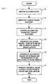
- Fig. 1 is an exemplary flowchart illustrating the method of applying SBs to a mask pattern in accordance with the present invention.
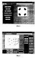
- Fig. 2 illustrates an exemplary Quasar illumination utilized in the example set forth below to describe the method of the present invention.
- Fig. 3 illustrates an exemplary contact hole pattern having randomly spaced contact holes.
- Fig. 4 illustrates an illumination map generated from the target contact hole pattern shown in Fig. 3 under the predefined illumination conditions illustrated in Fig. 2 .
- Figs. 5 and 6(a)-6(e) illustrate methods for extracting the SB features from the illumination map.
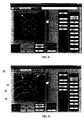
- Fig. 7 illustrates an exemplary modified mask design containing the 0-phase SBs positioned adjacent the desired contact holes 18 in accordance with the method of the present invention.
- Fig. 8 illustrates the resulting IM generated from only the 0-phased SBs.
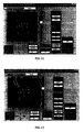
- Fig. 9 illustrates an exemplary resulting mask layout with both 0-phase SB features 2 land ⁇ -phase SB features 23.
- Fig. 10 shows the corresponding polygon plots of 0-phase SB features and ⁇ -phase SB features of the layout shown in Fig. 9 .
- Fig. 11 shows the intensity levels of the main contact features without the phase-balanced SB features of the present invention applied to the original mask layout.
- Fig. 12 illustrates the resulting intensity levels when the 0-phase SBs and the ⁇ -phased SBs are applied to the original mask layout.
- Fig. 13 shows the aerial image for a mask containing the main contact features and only the 0-phase SB features.
- Fig. 14 illustrates an exemplary processing system for implementing the mask design method of the present invention.
- Fig. 15 schematically depicts a lithographic projection apparatus suitable for use with the masks designed with the aid of the current invention.
- the OPC technique of the present invention allows for a full-pitch range of deep sub-wavelength mask patterns to be imaged utilizing substantially any illumination condition.
- the OPC technique entails generating an interference map (IM) based on the mask design (i.e., target pattern), which indicates how each point in the field surrounding the desired target pattern interacts with the target pattern.
- IM interference map
- the possibilities are that a given point either constructively interferes, destructively interferes or is neutral (i.e., neither constructive or destructive interference) with respect to the target pattern.
- IM i.e., SBs
- a second IM is generated based on the placement of the 0-phase assist features, which indicates how each point in the field surrounding the 0-phase assist features interacts with one another.
- ⁇ -phase assist features are placed in locations in which the 0-phase assist features are interacting constructively with one another (i.e., at locations other than the desired target features) so as to locally phase balance the 0-phase assist features and further reduce the likelihood of the 0-phase assist features being printed on the substrate.
- the phases of the SBs are defined with respect to the main features, therefore, 0-phased SBs have the exact same phase as the main features, for example, the contacts; while ⁇ -phased SBs have 180 degrees of phase difference relative to the main features.
- the creation of the ⁇ -phased SBs can be realized, for example, either through etching the mask substrate with accurate depth or through the use of phase-shifting materials.
- Fig. 1 is an exemplary flowchart detailing the steps in the foregoing process. This process will be described utilizing an example of a contact hole target pattern.
- the first step (Step 12) in the process is to define the illumination and settings of the optical imaging system that will be utilized to image the mask.
- the optimum placement of SB features also referred to as assist features
- the illumination and other optical settings e.g., NA, ⁇ in , ⁇ out , etc.
- the method of the present invention can be utilized with substantially any illumination, including highly coherent on-axis (partial coherence ⁇ 0.4) and strong off-axis illuminations (such as, for example, Quasar, C-Quasar, double dipole, and single dipole illumination), or a customized illumination type.
- Step 14 The next step (Step 14) in the process is to identify the target mask pattern to which SBs are to be added.
- the method of the present invention will typically be implemented in a computer program, such as MaskWeaver TM offered for sale by ASML MaskTools, Inc., so as to allow the process of the present invention to be performed in a substantially automated manner.
- the operator can either identify which portion of the target pattern the SBs should be applied to, or have the SBs applied to all portions of the target pattern.
- Fig. 3 illustrates an exemplary contact hole pattern having randomly spaced contact holes 18 to be imaged on the substrate.
- the next step (Step 16) in the process is to generate an interference map based on the target pattern.
- the exemplary contact hole pattern shown in Fig. 3 will be utilized to illustrate the process.
- the interference map is essentially an electric field (E-field) distribution at the time of exposure as formed by the target design features utilizing the defined illumination conditions and settings. By utilizing this E-field distribution, it is possible to extract the relative phase information necessary for the optimum placement of SB features.
- E-field electric field
- the IM indicates at each point (e.g., a grid point) in an optical region of interest for any given pattern whether transmitted light at that point will interfere constructively with the desired target pattern (thereby making the intensity of the transmitted light on the target pattern greater), destructively (thereby making the intensity of the transmitted light on the target pattern lower), or neutral (not altering the intensity of the transmitted light on the target pattern).
- the IM can be generated utilizing numerous methods, for example, using a conventional aerial image simulator as disclosed in US Patent Application No. 2004/0209170 , or an eigenvalued image model kernel as disclosed in US Provisional Patent Application Serial No. 60/530,656 filed on December 19, 2003 .
- the E-field distribution (or interference map) for a given mask pattern can be understood in a statistical sense.
- the phase relationship of the interference map at different locations is statistically stationary.
- Step 20 The E-field distribution or illumination map associated with the target contact hole pattern shown in Fig. 3 under the predefined illumination conditions illustrated in Fig. 2 is shown in Fig. 4 .
- the next step (Step 20) in the process is to extract or identify the locations in the mask layout where 0-phase SB should be positioned, along with the shape of the SB at each given location. It is noted that it is possible for the shape and size of each 0-phase SB to be different. Of course, it is also possible the SB to have the same shape and size, with the orientation of the SB within the mask layout being variable.
- the interference map illustrates the phase relationship and the relative interaction strength of the target contact hole mask pattern during the exposure. If the phases of the E-field at the main contact features 18 are maintained as a reference point at 0, any 0-phase SB feature placed at a location that has positive E-field value will interact with the neighboring contact holes 18 to be printed in a constructive manner. In other words, the SB features placed in these locations will act to enhance the printing of the main contact hole features 18.
- the 0-phase areas suitable for SB placement can be outlined by a contour with a fixed E-field value threshold setting of the IM.
- the extraction refers to the process of generating regular-shaped polygons based on the contoured areas that have been identified as the optimum locations for SB placement. From the mask manufacturing perspective, it is best to have the extracted SB features conform to the manufacturing restrictions as defined by the tool to be utilized to actually fabricate the mask.
- the restrictions can be expressed, for example, in terms of SB feature dimension and shape. In the given example, the rectangle shape and octagon shape SB features are demonstrated.
- the present invention is not limited to these shapes. Other shapes are certainly applicable as long as it can be produced and inspected under the existing and/or by the future mask making processes to ensure the production worthy quality.
- the optimization process (to define a threshold which does not result in an excessive number of areas on the IM being identified as requiring a 0-phased SB) will require some trial and error to determine an optimum E-field threshold setting to define the contours of interest (i.e., areas to receive 0-phased SBs).
- a proper rectangle SB can be placed with correct orientation in the island so that optimal SB effect can be achieved under SB orientation constraints.
- the size of the SB is determined by the lengths of the two principal axes in combination with the predefined SB length and width constraints that are imposed by SB manufacturability and printability.
- a set of pre-defined restrictions e.g., maximum width and length
- the definition of the minimum width and length can be defined in order to conform to mask making manufacturability, and be based on the imaging system and processing conditions that will be utilized to image the mask.
- an exclusion region around the desired contact hole can also be defined, in which it is impermissible to place SBs. Such an exclusion region prevents SBs from causing main feature distortion during printing.
- Fig. 7 illustrates the modified mask design containing the 0-phase SBs 21 positioned adjacent the desired contact holes 18 in accordance with the foregoing method.
- the 0-phase SBs 21 are placed only in locations within the mask design having an e-field value exceeding the predetermined threshold which is determined in the manner set forth above.
- the method used to size and orient the 0-phase SBs is method no. 2 discussed above.
- the 0-phase SB features 21 and the main contact hole features 18 have the same phase, which in this example is 0-phase shift, with respect to light transmitted through the features. This is so that the E-fields generated from 0-phase SB features 21 interact constructively with E-fields from the contact hole locations. As a result, the E-fields (and intensity levels) are strengthened in the main contact hole features 18, and the contact hole features 18 become more printable and with improved process latitude.
- the dimension of the 0-phase SB features should be as large as possible so long as 0-phase SBs remain subresolution (i.e., the 0-phase SBs are not printable).
- the 0-phase SB features 21 have e-field values that have the same sign as that of the E-fields from the main contact features 18. While this can enhance the printability of the main contact features 18, it must also be recognized that the optical interaction between these features is reciprocal. This means that the intensity levels of the 0-phase SB features 21 also become enhanced and more printable.
- the present invention utilizes ⁇ -phase SBs 23 to locally phase balance the 0-phase SB 21.
- the mask design is further modified to include ⁇ -phase SBs 23.
- the method includes placing ⁇ -phase (or out-of-phase) SB features 23 in the neighborhood of the 0-phase counterpart SBs to locally "balance" the relative 0- ⁇ phases.
- the important point is to ensure that the E-fields from phase-balanced SB features only interact destructively with each other while maintaining the constructive interactions between the 0-phase SB features 21 and the main contact holes 10.
- Placement of the ⁇ -phase SBs within the mask design is performed as follows. Referring again to Fig. 1 , a second IM is generated based on only the 0-phase SBs determined to be included in the mask design (Step 22). The resulting IM identifies the locations within the mask layout in which light incident upon these locations constructively interferes with the printing of the 0-phase SBs 21. In accordance with the present invention, by placing ⁇ -phased SBs 23 at these locations, the ⁇ -phased SBs, which exhibit a 180 degree phase difference with respect to light transmission, function to negate or suppress the constructive interaction between the 0-phased SBs 21. It is noted that the ⁇ -phased SBs can be extracted from the IM in the same manner as the 0-phased SBs discussed above. Fig. 8 illustrates the resulting IM corresponding to only the 0-phased SBs defined in Step 20.
- the original mask layout i.e., target pattern
- the original mask layout is modified to include both the 0-phased SBs 21 and the ⁇ -phased SBs 23 (Step 24), and this mask having the desired contact holes 18, the 0-phased SB features 21 and the ⁇ -phased SB features 23 represents the actual mask pattern to be imaged.
- Fig. 9 illustrates the resulting mask layout with both 0-phase SB features 21 and ⁇ -phase SB features 23 as extracted without any further fine-tuning
- Fig. 10 shows the corresponding polygon plots of 0-phase SB features 21 and ⁇ -phase SB features 23.
- bold polygons are the ⁇ -phase SB features 23
- bold polygons are 0-phase SB features 21
- the remaining features are the main contact hole square features 18.
- Fig. 11 shows the intensity levels of the main contact features without the phase-balanced SB features (i.e., without any scattering bars) applied to the mask pattern. As shown by Fig. 11 , the intensity levels are approximately 1.8.
- Fig. 12 illustrates the resulting intensity levels when the 0-phased SBs and ⁇ -phased SBs are applied to mask layout. As shown by Fig. 12 , the main contact features have significantly brighter intensity levels (approximately 0.35) when with phase-balanced SB features are contained in the mask. Indeed, the intensity levels are nearly double the relative intensity level for the main contact features obtained without the use of the phase-balanced SB features.
- the contact hole features must sometimes also go through the subsequent mode OPC step in the presence of the phase-balanced SB features.
- SBs are assist features which help the contact hole printing, but the contact sizes can still be off from the desired the target sizes.
- additional OPC steps can be applied to the model process.
- Fig. 13 shows the aerial image for a mask containing the main contact features and only the 0-phase SB features. Comparing the aerial image of Fig. 13 to the aerial image of Fig. 12 , it is clear that intensity levels at 0-phase SB locations are sufficiently suppressed overall, see, example site 1 of 0-phase SB in Fig. 13 versus the corresponding site of Fig. 12 when the "balanced" ⁇ -phase SB features are included in the mask layout. As for the intensity levels of the main contact hole features, the example site 2 shows little degradation from Fig. 13 to Fig. 12 . This is achieved due to 0- ⁇ phase balancing of the present invention.
- adjusting the size of the exclusion zone of the main contact features can effectively optimize the 0- ⁇ SB phase balancing.
- the ⁇ phase SBs are generated using the interference map of 0-phase SBs and with a certain range beyond the main contact features excluded. The range of exclusion is an effective variable for adjusting the balance for the 0- ⁇ SBs.
- the size of 0-phase SBs may be further restricted because otherwise there would not be sufficient room to insert the ⁇ -phase SBs.
- due to the proximity effect it has been determined that it is possible to achieve comparable printing results by adjusting the size of 0-phase SBs.
- the size of 0-phase SB features is subject to less stringent restrictions and a wider range of ⁇ -phase SBs can be utilized for phase balancing. Therefore, in the more isolated regions, both 0-phase SB features and ⁇ -phase SB features can be enlarged to further enhance the printability of the isolated contacts as long as they are balanced. With current geometry manipulation engines, automatic labeling and size adjustment for those phase balanced SBs can be readily accomplished.
- Fig. 14 illustrates an exemplary processing system for implementing the mask design method of the present invention.
- an exemplary processing system may contain a processor 1000 which receives input from an input 1003.
- Processor 1000 may be a conventional microprocessor or may be a specially designed processing unit, such as an EEPROM or EPROM or a fabricated integrated circuit.
- Input 1003 may be any type of electronic input device, such as a keyboard or a mouse, or may be a memory or internet connection.
- Processor 1000 preferably retrieves stored protocols from ROM 1002 and RAM 1001, such as protocols to implement the methods detailed above for generating a mask layout in accordance with the present invention, and stores information on RAM 1001.
- the calculated results (e.g., mask design) of processor 1000 may be displayed on display 1004 and may be provided to a mask fabrication unit.
- Fig. 15 schematically depicts a lithographic projection apparatus suitable for use with the masks designed with the aid of the current invention.
- the apparatus comprises:
- the apparatus is of a transmissive type (i.e. has a transmissive mask). However, in general, it may also be of a reflective type, for example (with a reflective mask). Alternatively, the apparatus may employ another kind of patterning means as an alternative to the use of a mask; examples include a programmable mirror array or LCD matrix.
- the source LA e.g. a mercury lamp, excimer laser or plasma discharge source
- the source LA produces a beam of radiation.
- This beam is fed into an illumination system (illuminator) IL, either directly or after having traversed conditioning means, such as a beam expander Ex, for example.
- the illuminator IL may comprise adjusting means AM for setting the outer and/or inner radial extent (commonly referred to as ⁇ -outer and ⁇ -inner, respectively) of the intensity distribution in the beam.
- ⁇ -outer and ⁇ -inner respectively
- the beam PB impinging on the mask MA has a desired uniformity and intensity distribution in its cross-section.
- the source LA may be within the housing of the lithographic projection apparatus (as is often the case when the source LA is a mercury lamp, for example), but that it may also be remote from the lithographic projection apparatus, the radiation beam that it produces being led into the apparatus (e.g. with the aid of suitable directing mirrors); this latter scenario is often the case when the source LA is an excimer laser (e.g. based on KrF, ArF or F 2 lasing).
- the current invention encompasses both of these scenarios.
- the beam PB subsequently intercepts the mask MA, which is held on a mask table MT. Having traversed the mask MA, the beam PB passes through the lens PL, which focuses the beam PB onto a target portion C of the substrate W. With the aid of the second positioning means (and interferometric measuring means IF), the substrate table WT can be moved accurately, e.g. so as to position different target portions C in the path of the beam PB. Similarly, the first positioning means can be used to accurately position the mask MA with respect to the path of the beam PB, e.g. after mechanical retrieval of the mask MA from a mask library, or during a scan.
- the object tables MT, WT will be realized with the aid of a long-stroke module (coarse positioning) and a short-stroke module (fine positioning), which are not explicitly depicted in Fig. 15 .
- the mask table MT may just be connected to a short stroke actuator, or may be fixed.
- the depicted tool can be used in two different modes:
- the software functionalities of a computer system involve programming, including executable code, may be used to implement the above described imaging model.
- the software code is executable by the general-purpose computer.
- the code and possibly the associated data records are stored within a general-purpose computer platform.
- the software may be stored at other locations and/or transported for loading into the appropriate general-purpose computer systems.
- the embodiments discussed above involve one or more software products in the form of one or more modules of code carried by at least one machine-readable medium. Execution of such code by a processor of the computer system enables the platform to implement the catalog and/or software downloading functions, in essentially the manner performed in the embodiments discussed and illustrated herein.
- Non-volatile media include, for example, optical or magnetic disks, such as any of the storage devices in any computer(s) operating as one of the server platform, discussed above.
- Volatile media include dynamic memory, such as main memory of such a computer platform.
- Physical transmission media include coaxial cables; copper wire and fiber optics, including the wires that comprise a bus within a computer system.
- Carrier-wave transmission media can take the form of electric or electromagnetic signals, or acoustic or light waves such as those generated during radio frequency (RF) and infrared (IR) data communications.
- Common forms of computer-readable media therefore include, for example: a floppy disk, a flexible disk, hard disk, magnetic tape, any other magnetic medium, a CD-ROM, DVD, any other optical medium, less commonly used media such as punch cards, paper tape, any other physical medium with patterns of holes, a RAM, a PROM, and EPROM, a FLASH-EPROM, any other memory chip or cartridge, a carrier wave transporting data or instructions, cables or links transporting such a carrier wave, or any other medium from which a computer can read programming code and/or data.
- Many of these forms of computer readable media may be involved in carrying one or more sequences of one or more instructions to a processor for execution.
- the concepts disclosed herein may simulate or mathematically model any generic imaging system for imaging sub wavelength features, and may be especially useful with emerging imaging technologies capable of producing wavelengths of an increasingly smaller size.
- Emerging technologies already in use include EUV (extreme ultra violet) lithography that is capable of producing a 193nm wavelength with the use of a ArF laser, and even a 157nm wavelength with the use of a Fluorine laser.
- EUV lithography is capable of producing wavelengths within a range of 20-5nm by using a synchrotron or by hitting a material (either solid or a plasma) with high energy electrons in order to produce photons within this range.
- illumination may be produced by reflective mirrors with a multi-stack of Molybdenum and Silicon.
- the multi-stack mirror has a 40 layer pairs of Molybdenum and Silicon where the thickness of each layer is a quarter wavelength. Even smaller wavelengths may be produced with X-ray lithography.
- a synchrotron is used to produce an X-ray wavelength. Since most material is absorptive at x-ray wavelengths, a thin piece of absorbing material defines where features would print (positive resist) or not print (negative resist).
Claims (16)
- Procédé de production d'une conception de masque ayant des caractéristiques de correction de proximité optique disposées dans celle-ci, ledit procédé comprenant les étapes suivantes :obtenir (14) un motif cible voulu ayant des caractéristiques (18) à imager sur un substrat ;déterminer (16) une première carte d'interférence sur la base dudit motif cible, ladite première carte d'interférence définissant des zones d'interférence constructives entre au moins une desdites caractéristiques à imager et une zone de champ adjacente à ladite au moins une caractéristique ; etplacer (20) un premier ensemble de caractéristiques d'assistance (21) ayant une première phase dans la conception de masque sur la base des zones d'interférence constructive définies par ladite première carte d'interférence ; caractérisé par :dans lequel ladite première phase n'est pas égale à ladite seconde phase.déterminer (22) une seconde carte d'interférence sur la base dudit premier ensemble de caractéristiques d'assistance, ladite seconde carte d'interférence définissant des zones d'interférence constructive entre des caractéristiques d'assistance dudit premier ensemble de caractéristiques d'assistance et une zone de champ adjacente à au moins une desdites caractéristiques d'assistance dudit premier ensemble de caractéristiques d'assistance; etplacer (24) un second ensemble de caractéristiques d'assistance (23) ayant une seconde phase dans la conception de masque sur la base des zones d'interférence constructive définies par la seconde carte d'interférence,
- Procédé selon la revendication 1, dans lequel chaque caractéristique d'assistance (23) dudit second ensemble de caractéristiques d'assistance présente un déphasage de 180° par rapport à chaque caractéristique d'assistance dudit premier ensemble de caractéristiques d'assistance.
- Procédé selon la revendication 1 ou 2, comportant de plus l'étape consistant à définir une zone d'exclusion qui entoure au moins une caractéristique (18) dans ledit motif cible,
dans lequel ni une caractéristique d'assistance provenant du premier ensemble de caractéristiques d'assistance ni une caractéristique d'assistance provenant du second ensemble de caractéristiques d'assistance n'est positionnée dans la région d'exclusion. - Procédé selon la revendication 1, 2 ou 3, dans lequel les caractéristiques d'assistance (21) du premier ensemble de caractéristiques d'assistance renforcent l'impression desdites caractéristiques de la cible voulue et sont disposées dans des zones d'interférence constructive, et des caractéristiques d'assistance (23) du second ensemble de caractéristiques d'assistance annulent l'interférence constructive survenant entre des caractéristiques d'assistance contenues dans le premier ensemble de caractéristiques d'assistance.
- Procédé selon la revendication 1, 2, 3 ou 4, dans lequel la première carte d'interférence définit des niveaux d'intensité du champ relatif aux caractéristiques (18) à imager, ladite première carte d'interférence étant capable de représenter à la fois des valeurs positives et des valeurs négatives de l'intensité par rapport à un niveau de DC non nul,
dans lequel des régions du champ ayant des valeurs d'intensité qui sont positives par rapport audit niveau de DC non nul correspondent à des zones d'interférence constructive, et des régions du champ ayant des valeurs d'intensité qui sont négatives par rapport audit niveau de DC non nul correspondent à des zones destructrices des zones d'interférence. - Procédé selon la revendication 1, 2, 3, 4 ou 5, dans lequel la seconde carte d'interférence définit des niveaux d'intensité du champ relatif au premier ensemble de caractéristiques d'assistance (21), ladite seconde carte d'interférence étant capable de représenter à la fois des valeurs positives et des valeurs négatives d'intensité par rapport à un niveau de DC non nul,
dans lequel des régions du champ ayant des valeurs d'intensité qui sont positives par rapport audit niveau de DC non nul correspondent à des zones d'interférence constructive, et des régions du champ ayant des valeurs d'intensité qui sont négatives par rapport audit niveau de DC non nul correspondent à des zones destructrices de zones d'interférence. - Procédé de fabrication d'un masque, comportant la production d'une conception de masque conformément au procédé selon l'une quelconque des revendications précédentes et la fabrication d'un masque physique conforme à la conception de masque dans laquelle lesdits premier et second ensembles de caractéristiques d'assistance ont été placés.
- Procédé de fabrication d'un masque, comportant la production d'une conception de masque conformément au procédé selon l'une quelconque des revendications 1 à 6 et la production d'un masque virtuel comportant un fichier ou des fichiers de données adaptés pour commander des moyens programmables de mise en forme conformément à la conception de masque dans laquelle lesdits premier et second ensembles de caractéristiques d'assistance ont été placés.
- Procédé de fabrication d'un dispositif comprenant la fabrication d'un masque physique ou virtuel selon le procédé de la revendication 7 ou 8 et l'utilisation du masque pour projeter une image du motif cible voulu sur un substrat.
- Appareil pour produire une conception de masque ayant des caractéristiques de correction de proximité optique disposées dans celle-ci, ledit appareil comportant :des moyens pour obtenir un motif cible voulu ayant des caractéristiques (18) à imager sur un substrat ;des moyens pour déterminer une première carte d'interférence sur la base dudit motif cible, ladite première carte d'interférence définissant des zones d'interférence constructive entre au moins une desdites caractéristiques à imager et une zone de champ adjacente à ladite au moins une caractéristique ; etdes moyens pour placer un premier ensemble de caractéristiques d'assistance (21) ayant une première phase dans la conception de masque sur la base des zones d'interférence constructive définies par ladite première carte d'interférence ; caractérisé par :dans lequel ladite première phase n'est pas égale à ladite seconde phase.des moyens pour déterminer une seconde carte d'interférence sur la base dudit premier ensemble de caractéristiques d'assistance (21), ladite seconde carte d'interférence définissant des zones d'interférence constructive entre des caractéristiques d'assistance dudit premier ensemble de caractéristiques d'assistance et une zone de champ adjacente à au moins une desdites caractéristiques d'assistance dudit premier ensemble de caractéristiques d'assistance ; etdes moyens pour placer un second ensemble de caractéristiques d'assistances (23) ayant une seconde phase dans la conception de masque sur la base des zones d'interférence constructive définies par la seconde carte d'interférence,
- Appareil selon la revendication 10, dans lequel chaque caractéristique d'assistance (23) dudit second ensemble de caractéristiques d'assistance présente un déphasage de 180° par rapport à chaque caractéristique d'assistance (21) dudit premier ensemble de caractéristiques d'assistance.
- Appareil selon la revendication 10 ou 11, comprenant de plus des moyens pour définir une région d'exclusion qui entoure au moins une caractéristique (18) dans ledit motif cible,
dans lequel ni une caractéristique d'assistance (21) provenant du premier ensemble de caractéristiques d'assistance ni une caractéristique d'assistance (23) provenant du second ensemble de caractéristiques d'assistance n'est positionnée dans la région d'exclusion. - Appareil selon la revendication 10, 11 ou 12, dans lequel les caractéristiques d'assistance (21) du premier ensemble de caractéristiques d'assistance renforcent l'impression desdites caractéristiques (18) de la cible voulue et sont disposées dans des zones constructives d'interférence, et des caractéristiques d'assistance (23) du second ensemble de caractéristiques d'assistance annulent l'interférence constructive survenant entre des caractéristiques d'assistance (21) contenues dans le premier ensemble de caractéristiques d'assistance.
- Appareil selon la revendication 10, 11, 12 ou 13, dans lequel la première carte d'interférence définit des niveaux d'intensité du champ relatif aux caractéristiques (18) à imager, ladite première carte d'interférence étant capable de représenter à la fois des valeurs positives et des valeurs négatives de l'intensité par rapport à un niveau de DC non nul,
dans lequel des régions du champ ayant des valeurs d'intensité qui sont positives par rapport audit niveau de DC non nul correspondent à des zones constructives d'interférence, et des régions du champ ayant des valeurs d'intensité qui sont négatives par rapport audit niveau de DC non nul correspondent à des zones destructives des zones d'interférence. - Appareil selon la revendication 10, 11, 12, 13 ou 14, dans lequel la seconde carte d'interférence définit des niveaux d'intensité du champ par rapport au premier ensemble de caractéristiques d'assistance (21), ladite seconde carte d'interférence étant capable de représenter à la fois des valeurs positives et des valeurs négatives d'intensité par rapport à un niveau de DC non nul,
dans lequel des régions du champ ayant des valeurs d'intensité qui sont positives par rapport audit niveau de DC non nul correspondent à des zones constructives d'interférence, et des régions du champ ayant des valeurs d'intensité qui sont négatives par rapport audit niveau de DC non nul correspondent à des zones destructives de zones d'interférence. - Programme informatique comprenant des moyens de codage de programme qui, lorsqu'ils sont exécutés sur un système informatique, donnent pour instruction au système informatique d'effectuer un procédé selon l'une quelconque des revendications 1 à 6 ou 8.
Applications Claiming Priority (2)
| Application Number | Priority Date | Filing Date | Title |
|---|---|---|---|
| US50026003P | 2003-09-05 | 2003-09-05 | |
| US500260P | 2003-09-05 |
Publications (3)
| Publication Number | Publication Date |
|---|---|
| EP1513012A2 EP1513012A2 (fr) | 2005-03-09 |
| EP1513012A3 EP1513012A3 (fr) | 2006-02-22 |
| EP1513012B1 true EP1513012B1 (fr) | 2008-02-20 |
Family
ID=34135370
Family Applications (1)
| Application Number | Title | Priority Date | Filing Date |
|---|---|---|---|
| EP04255386A Expired - Fee Related EP1513012B1 (fr) | 2003-09-05 | 2004-09-03 | Procédé et dispositif de placement des structures auxiliaires balancés en phase utilisant un modèle pour lithographie optique avec une résolution au-dessous de la longeur d'onde d'exposition |
Country Status (8)
| Country | Link |
|---|---|
| US (1) | US7550235B2 (fr) |
| EP (1) | EP1513012B1 (fr) |
| JP (1) | JP4659425B2 (fr) |
| KR (1) | KR20050025095A (fr) |
| CN (1) | CN100465789C (fr) |
| DE (1) | DE602004011860T2 (fr) |
| SG (1) | SG109607A1 (fr) |
| TW (1) | TW200519526A (fr) |
Families Citing this family (32)
| Publication number | Priority date | Publication date | Assignee | Title |
|---|---|---|---|---|
| US7620930B2 (en) | 2004-08-24 | 2009-11-17 | Asml Masktools B.V. | Method, program product and apparatus for model based scattering bar placement for enhanced depth of focus in quarter-wavelength lithography |
| CN1800971A (zh) * | 2004-09-14 | 2006-07-12 | Asml蒙片工具有限公司 | 一种用于实施全芯片制造可靠性检查和校正的方法 |
| WO2006138410A2 (fr) * | 2005-06-14 | 2006-12-28 | Cadence Design Systems, Inc. | Procede et systeme permettant d'utiliser un appariement de formes pour traiter une conception de circuit integre |
| US7266798B2 (en) * | 2005-10-12 | 2007-09-04 | International Business Machines Corporation | Designer's intent tolerance bands for proximity correction and checking |
| US7614034B2 (en) * | 2005-11-08 | 2009-11-03 | Asml Masktools B.V. | Method and apparatus for generating OPC rules for placement of scattering bar features utilizing interface mapping technology |
| US7493589B2 (en) * | 2005-12-29 | 2009-02-17 | Asml Masktools B.V. | Method, program product and apparatus for model based geometry decomposition for use in a multiple exposure process |
| US7604909B2 (en) * | 2005-12-29 | 2009-10-20 | Asml Masktools B.V. | Method for improved manufacturability and patterning of sub-wavelength contact hole mask |
| CN101086622B (zh) * | 2006-06-08 | 2010-05-12 | 中芯国际集成电路制造(上海)有限公司 | 一种应用反散射带的方法 |
| JP5235322B2 (ja) | 2006-07-12 | 2013-07-10 | キヤノン株式会社 | 原版データ作成方法及び原版データ作成プログラム |
| JP2008076683A (ja) * | 2006-09-20 | 2008-04-03 | Canon Inc | 原版データ作成プログラム、原版データ作成方法、原版作成方法、露光方法及びデバイスの製造方法 |
| CN101681093B (zh) * | 2007-06-04 | 2012-05-30 | Asml荷兰有限公司 | 用于实施基于模型的光刻引导的布局设计的方法 |
| KR100891336B1 (ko) * | 2007-07-05 | 2009-03-31 | 삼성전자주식회사 | 마스크 레이아웃 이미지의 생성 방법, 이를 수행하는프로그래밍된 명령을 저장하는 컴퓨터에서 판독 가능한저장 매체 및 이미징 시스템 |
| JP4484909B2 (ja) * | 2007-07-24 | 2010-06-16 | キヤノン株式会社 | 原版データ作成方法、原版作成方法、露光方法および原版データ作成プログラム |
| US9779186B2 (en) | 2007-08-28 | 2017-10-03 | Asml Netherlands B.V. | Methods for performing model-based lithography guided layout design |
| EP2040120B1 (fr) | 2007-09-19 | 2011-03-02 | Canon Kabushiki Kaisha | Procédé de génération de données de masque, procédé de fabrication de masque, procédé d'exposition, procédé de fabrication de dispositif, et logiciel |
| JP2009093138A (ja) * | 2007-09-19 | 2009-04-30 | Canon Inc | 原版データの生成方法、原版作成方法、露光方法、デバイス製造方法及び原版データを作成するためのプログラム |
| JP5607308B2 (ja) * | 2009-01-09 | 2014-10-15 | キヤノン株式会社 | 原版データ生成プログラムおよび方法 |
| JP5607348B2 (ja) * | 2009-01-19 | 2014-10-15 | キヤノン株式会社 | 原版データを生成する方法およびプログラム、ならびに、原版製作方法 |
| US8166423B2 (en) * | 2009-09-08 | 2012-04-24 | International Business Machines Corporation | Photomask design verification |
| US8122597B2 (en) * | 2010-05-07 | 2012-02-28 | Digital Graphics Incorporation | Method for fabricating light emitting diode signboard |
| US8739078B2 (en) | 2012-01-18 | 2014-05-27 | International Business Machines Corporation | Near-neighbor trimming of dummy fill shapes with built-in optical proximity corrections for semiconductor applications |
| KR101991380B1 (ko) | 2012-07-26 | 2019-06-20 | 삼성전자주식회사 | 반도체 소자의 레이아웃 생성 방법 |
| US9223911B2 (en) | 2014-01-30 | 2015-12-29 | Globalfoundries Inc. | Optical model employing phase transmission values for sub-resolution assist features |
| US9310674B2 (en) | 2014-02-20 | 2016-04-12 | International Business Machines Corporation | Mask that provides improved focus control using orthogonal edges |
| KR102238742B1 (ko) * | 2014-09-11 | 2021-04-12 | 삼성전자주식회사 | 마스크 패턴의 측정 관심 영역 그룹화 방법 및 이를 이용한 마스크 패턴의 선폭 계측 방법 |
| CN104391425B (zh) * | 2014-10-20 | 2019-01-22 | 中国科学院微电子研究所 | 一种小间隙平面电极的制作方法 |
| KR102335186B1 (ko) * | 2014-12-24 | 2021-12-03 | 삼성전자주식회사 | 렌즈 조립체, 이를 이용한 장애물 감지유닛, 및 이를 구비한 이동로봇 |
| CN106444272A (zh) * | 2016-09-30 | 2017-02-22 | 上海华虹宏力半导体制造有限公司 | 光刻工艺中光学临近修正方法 |
| US10522322B2 (en) | 2017-04-13 | 2019-12-31 | Fractilia, Llc | System and method for generating and analyzing roughness measurements |
| US10176966B1 (en) | 2017-04-13 | 2019-01-08 | Fractilia, Llc | Edge detection system |
| CN108153115A (zh) * | 2017-12-19 | 2018-06-12 | 上海集成电路研发中心有限公司 | 极紫外光刻掩模、其制作方法及生成掩模图案的方法 |
| CN110119065B (zh) * | 2018-02-06 | 2022-08-26 | 中芯国际集成电路制造(天津)有限公司 | 图形优化方法及掩膜版的制备方法 |
Family Cites Families (24)
| Publication number | Priority date | Publication date | Assignee | Title |
|---|---|---|---|---|
| JPS60234320A (ja) * | 1984-05-08 | 1985-11-21 | Hitachi Ltd | フオトマスクの欠陥修正方法及び装置 |
| JPH04216548A (ja) * | 1990-12-18 | 1992-08-06 | Mitsubishi Electric Corp | フォトマスク |
| KR960002536A (fr) * | 1994-06-29 | 1996-01-26 | ||
| US5682323A (en) * | 1995-03-06 | 1997-10-28 | Lsi Logic Corporation | System and method for performing optical proximity correction on macrocell libraries |
| US5663893A (en) * | 1995-05-03 | 1997-09-02 | Microunity Systems Engineering, Inc. | Method for generating proximity correction features for a lithographic mask pattern |
| US6223139B1 (en) * | 1998-09-15 | 2001-04-24 | International Business Machines Corporation | Kernel-based fast aerial image computation for a large scale design of integrated circuit patterns |
| JP3275863B2 (ja) * | 1999-01-08 | 2002-04-22 | 日本電気株式会社 | フォトマスク |
| US6214497B1 (en) * | 1999-06-29 | 2001-04-10 | Micron Technology, Inc. | Method to eliminate side lobe printing of attenuated phase shift masks |
| US6303253B1 (en) * | 2000-03-16 | 2001-10-16 | International Business Machines Corporation | Hierarchy and domain-balancing method and algorithm for serif mask design in microlithography |
| US6777141B2 (en) * | 2000-07-05 | 2004-08-17 | Numerical Technologies, Inc. | Phase shift mask including sub-resolution assist features for isolated spaces |
| US6787271B2 (en) * | 2000-07-05 | 2004-09-07 | Numerical Technologies, Inc. | Design and layout of phase shifting photolithographic masks |
| TW552561B (en) | 2000-09-12 | 2003-09-11 | Asml Masktools Bv | Method and apparatus for fast aerial image simulation |
| US6901575B2 (en) * | 2000-10-25 | 2005-05-31 | Numerical Technologies, Inc. | Resolving phase-shift conflicts in layouts using weighted links between phase shifters |
| TWI285295B (en) * | 2001-02-23 | 2007-08-11 | Asml Netherlands Bv | Illumination optimization in lithography |
| US6519760B2 (en) * | 2001-02-28 | 2003-02-11 | Asml Masktools, B.V. | Method and apparatus for minimizing optical proximity effects |
| US6792591B2 (en) * | 2001-02-28 | 2004-09-14 | Asml Masktools B.V. | Method of identifying an extreme interaction pitch region, methods of designing mask patterns and manufacturing masks, device manufacturing methods and computer programs |
| KR100576752B1 (ko) * | 2001-10-09 | 2006-05-03 | 에이에스엠엘 마스크툴즈 비.브이. | 2차원 피처모델 캘리브레이션 및 최적화 방법 |
| JP4191923B2 (ja) * | 2001-11-02 | 2008-12-03 | 株式会社東芝 | 露光方法および露光装置 |
| US6749970B2 (en) | 2001-12-11 | 2004-06-15 | Advanced Micro Devices, Inc. | Method of enhancing clear field phase shift masks with border regions around phase 0 and phase 180 regions |
| US6887633B2 (en) * | 2002-02-08 | 2005-05-03 | Chih-Hsien Nail Tang | Resolution enhancing technology using phase assignment bridges |
| US7023528B2 (en) * | 2002-06-10 | 2006-04-04 | International Business Machines Corporation | Hybrid electronic mask |
| US6807662B2 (en) * | 2002-07-09 | 2004-10-19 | Mentor Graphics Corporation | Performance of integrated circuit components via a multiple exposure technique |
| US7266480B2 (en) * | 2002-10-01 | 2007-09-04 | The Regents Of The University Of California | Rapid scattering simulation of objects in imaging using edge domain decomposition |
| US6964032B2 (en) * | 2003-02-28 | 2005-11-08 | International Business Machines Corporation | Pitch-based subresolution assist feature design |
-
2004
- 2004-09-03 TW TW093126696A patent/TW200519526A/zh unknown
- 2004-09-03 US US10/933,496 patent/US7550235B2/en active Active
- 2004-09-03 SG SG200405018A patent/SG109607A1/en unknown
- 2004-09-03 EP EP04255386A patent/EP1513012B1/fr not_active Expired - Fee Related
- 2004-09-03 DE DE602004011860T patent/DE602004011860T2/de not_active Expired - Fee Related
- 2004-09-06 CN CNB2004100997929A patent/CN100465789C/zh not_active Expired - Fee Related
- 2004-09-06 KR KR1020040070727A patent/KR20050025095A/ko not_active Application Discontinuation
- 2004-09-06 JP JP2004293098A patent/JP4659425B2/ja not_active Expired - Fee Related
Also Published As
| Publication number | Publication date |
|---|---|
| SG109607A1 (en) | 2005-03-30 |
| DE602004011860D1 (de) | 2008-04-03 |
| KR20050025095A (ko) | 2005-03-11 |
| JP2005122163A (ja) | 2005-05-12 |
| US7550235B2 (en) | 2009-06-23 |
| TW200519526A (en) | 2005-06-16 |
| EP1513012A3 (fr) | 2006-02-22 |
| US20050142449A1 (en) | 2005-06-30 |
| DE602004011860T2 (de) | 2009-02-12 |
| CN1664702A (zh) | 2005-09-07 |
| JP4659425B2 (ja) | 2011-03-30 |
| EP1513012A2 (fr) | 2005-03-09 |
| CN100465789C (zh) | 2009-03-04 |
Similar Documents
| Publication | Publication Date | Title |
|---|---|---|
| EP1513012B1 (fr) | Procédé et dispositif de placement des structures auxiliaires balancés en phase utilisant un modèle pour lithographie optique avec une résolution au-dessous de la longeur d'onde d'exposition | |
| EP1439419B1 (fr) | Méthode et appareil pour attribuer des éléments de correction de l'effet de proximité optique à un masque pour la lithographie optique | |
| EP1420294B1 (fr) | Méthode et appareil pour la conversion des données d'un tracé sur la base d'un modèle, dans le but d'une exposition dipolaire | |
| US7594199B2 (en) | Method of optical proximity correction design for contact hole mask | |
| EP1712954B1 (fr) | Procédé et produit de programme de réalisation d'une lithographie à double exposition | |
| US7549140B2 (en) | Method and apparatus for decomposing semiconductor device patterns into phase and chrome regions for chromeless phase lithography | |
| US7399559B2 (en) | Optical proximity correction method utilizing phase-edges as sub-resolution assist features | |
| KR100927454B1 (ko) | 개선된 간섭 매핑 리소그래피를 이용하는 피처 최적화 | |
| US20040265707A1 (en) | Source and mask optimization | |
| EP1235103B1 (fr) | Méthode de correction de l'effet de proximité au moyen de structures auxiliaires non résolues à transmissivité partielle | |
| US7604909B2 (en) | Method for improved manufacturability and patterning of sub-wavelength contact hole mask | |
| US7614034B2 (en) | Method and apparatus for generating OPC rules for placement of scattering bar features utilizing interface mapping technology |
Legal Events
| Date | Code | Title | Description |
|---|---|---|---|
| PUAI | Public reference made under article 153(3) epc to a published international application that has entered the european phase |
Free format text: ORIGINAL CODE: 0009012 |
|
| AK | Designated contracting states |
Kind code of ref document: A2 Designated state(s): AT BE BG CH CY CZ DE DK EE ES FI FR GB GR HU IE IT LI LU MC NL PL PT RO SE SI SK TR |
|
| AX | Request for extension of the european patent |
Extension state: AL HR LT LV MK |
|
| PUAL | Search report despatched |
Free format text: ORIGINAL CODE: 0009013 |
|
| AK | Designated contracting states |
Kind code of ref document: A3 Designated state(s): AT BE BG CH CY CZ DE DK EE ES FI FR GB GR HU IE IT LI LU MC NL PL PT RO SE SI SK TR |
|
| AX | Request for extension of the european patent |
Extension state: AL HR LT LV MK |
|
| 17P | Request for examination filed |
Effective date: 20060725 |
|
| 17Q | First examination report despatched |
Effective date: 20060905 |
|
| AKX | Designation fees paid |
Designated state(s): DE FR GB IT NL |
|
| GRAP | Despatch of communication of intention to grant a patent |
Free format text: ORIGINAL CODE: EPIDOSNIGR1 |
|
| GRAS | Grant fee paid |
Free format text: ORIGINAL CODE: EPIDOSNIGR3 |
|
| GRAA | (expected) grant |
Free format text: ORIGINAL CODE: 0009210 |
|
| AK | Designated contracting states |
Kind code of ref document: B1 Designated state(s): DE FR GB IT NL |
|
| REG | Reference to a national code |
Ref country code: GB Ref legal event code: FG4D |
|
| REF | Corresponds to: |
Ref document number: 602004011860 Country of ref document: DE Date of ref document: 20080403 Kind code of ref document: P |
|
| ET | Fr: translation filed | ||
| PGFP | Annual fee paid to national office [announced via postgrant information from national office to epo] |
Ref country code: NL Payment date: 20080915 Year of fee payment: 5 Ref country code: IT Payment date: 20080920 Year of fee payment: 5 Ref country code: FR Payment date: 20080912 Year of fee payment: 5 |
|
| PLBE | No opposition filed within time limit |
Free format text: ORIGINAL CODE: 0009261 |
|
| STAA | Information on the status of an ep patent application or granted ep patent |
Free format text: STATUS: NO OPPOSITION FILED WITHIN TIME LIMIT |
|
| PGFP | Annual fee paid to national office [announced via postgrant information from national office to epo] |
Ref country code: GB Payment date: 20080918 Year of fee payment: 5 |
|
| 26N | No opposition filed |
Effective date: 20081121 |
|
| PGFP | Annual fee paid to national office [announced via postgrant information from national office to epo] |
Ref country code: DE Payment date: 20080919 Year of fee payment: 5 |
|
| REG | Reference to a national code |
Ref country code: NL Ref legal event code: V1 Effective date: 20100401 |
|
| GBPC | Gb: european patent ceased through non-payment of renewal fee |
Effective date: 20090903 |
|
| REG | Reference to a national code |
Ref country code: FR Ref legal event code: ST Effective date: 20100531 |
|
| PG25 | Lapsed in a contracting state [announced via postgrant information from national office to epo] |
Ref country code: NL Free format text: LAPSE BECAUSE OF NON-PAYMENT OF DUE FEES Effective date: 20100401 Ref country code: FR Free format text: LAPSE BECAUSE OF NON-PAYMENT OF DUE FEES Effective date: 20090930 Ref country code: DE Free format text: LAPSE BECAUSE OF NON-PAYMENT OF DUE FEES Effective date: 20100401 |
|
| PG25 | Lapsed in a contracting state [announced via postgrant information from national office to epo] |
Ref country code: GB Free format text: LAPSE BECAUSE OF NON-PAYMENT OF DUE FEES Effective date: 20090903 |
|
| PG25 | Lapsed in a contracting state [announced via postgrant information from national office to epo] |
Ref country code: IT Free format text: LAPSE BECAUSE OF NON-PAYMENT OF DUE FEES Effective date: 20090903 |