EP1512792B1 - Schutzschicht für den Bettungskörper eines Gleisfahrweges - Google Patents
Schutzschicht für den Bettungskörper eines Gleisfahrweges Download PDFInfo
- Publication number
- EP1512792B1 EP1512792B1 EP04017565A EP04017565A EP1512792B1 EP 1512792 B1 EP1512792 B1 EP 1512792B1 EP 04017565 A EP04017565 A EP 04017565A EP 04017565 A EP04017565 A EP 04017565A EP 1512792 B1 EP1512792 B1 EP 1512792B1
- Authority
- EP
- European Patent Office
- Prior art keywords
- protective layer
- track
- bedding
- earth
- shaped elements
- Prior art date
- Legal status (The legal status is an assumption and is not a legal conclusion. Google has not performed a legal analysis and makes no representation as to the accuracy of the status listed.)
- Expired - Lifetime
Links
Images
Classifications
-
- E—FIXED CONSTRUCTIONS
- E01—CONSTRUCTION OF ROADS, RAILWAYS, OR BRIDGES
- E01B—PERMANENT WAY; PERMANENT-WAY TOOLS; MACHINES FOR MAKING RAILWAYS OF ALL KINDS
- E01B1/00—Ballastway; Other means for supporting the sleepers or the track; Drainage of the ballastway
- E01B1/001—Track with ballast
-
- E—FIXED CONSTRUCTIONS
- E01—CONSTRUCTION OF ROADS, RAILWAYS, OR BRIDGES
- E01B—PERMANENT WAY; PERMANENT-WAY TOOLS; MACHINES FOR MAKING RAILWAYS OF ALL KINDS
- E01B19/00—Protection of permanent way against development of dust or against the effect of wind, sun, frost, or corrosion; Means to reduce development of noise
- E01B19/006—Means for protecting the underground against spillage
Definitions
- the invention relates to a track bed with ballast body, earth body and a protective layer which separates the ballast body against the upcoming earth body and has abutting plate-shaped elements with high compressive strength and low water absorbency at long-term contact with moisture.
- PSS anti-slip layers
- these mineral mixtures have a wasserableitende and bearing capacity-increasing effect and thus protect the ballast bed from waterlogging, frost damage and uneven settlements or uplift.
- the strength of the gravel sand layers to be installed vary not only strongly depending on the location, but that above all large amounts of earth material dug and transported, at the same time large quantities have to be delivered to new planum sand to be installed. Since these transport processes can usually only be done in the profile of the locked work track, they are associated with great mechanical engineering effort.
- DE 31 47 346 It is known to apply foam boards as a substitute for these PSS composed of mineral mixtures on the ballastless planum and thus to achieve a comparable effect as in the "classic" PSS. However, it has been found that no sufficiently joint-free laying of rigid foam panels could be achieved and thus the water-draining effect required by such a protective layer was not achievable. To achieve a better water seal suggests DE 31 47 346 the installation of two superimposed layers of rigid foam plates, wherein the joints of these two layers are to be arranged offset to one another in such a way. In construction site practice, however, this approach has proven to be less realistic.
- the GB 2 243 108 A discloses a protective layer which can be used for the construction of a track bed and which comprises a rigid core insert, preferably made of plastic, and upper and lower cover layers, which are manufactured from a more flexible geotextile material and wound around the core insert. Such an arrangement is intended to form a water-impermeable boundary layer for avoiding sludge rising from the substructure into the ballast layer.
- the invention has for its object to provide a track bed with ballast body, earth body and a protective layer which separates the ballast body against the upcoming earth body and abutting plate-shaped elements with high compressive strength and low water absorbency at long-term contact with moisture, to develop an improved transition region between a Ballast ensured with or without a protective layer.
- the protective layer should be suitable to rehabilitate existing rehabilitation-requiring routes with a lower logistics and machine use than before.
- the bearing behavior of the superstructure is to be improved in terms of dynamic and static loads from train traffic.
- the protective layer should be installable in a continuous conversion process with high propulsive power. It should be striven that no capital-intensive construction machinery requiring new construction be required, but that all necessary services should as far as possible be achievable with the existing machinery.
- the installation of this new protective layer should also be weather-independent than with the base layers of gravel-sand mixtures.
- the thickness of the plate-shaped elements continuously decreases in the transition region between a running with the plate-shaped elements and the nonwoven layer bed body and a run without planum protective bed body over a length of at least 20 meters and the minimum thickness of an element in the final area of the transition is still at least 0.04 meters.
- the preferred embodiment of the plate-shaped elements made of hard foam additionally offers the advantages of a very low thermal conductivity, a high modulus of elasticity, favorable fracture stress ratios and a low intrinsic weight, whereby a manual handling of the plate elements is possible.
- a folding of the rigid foam panels ensures a sufficiently positive connection of two elements.
- B 2 * y + SB.
- the size y corresponds to the vertical distance between the upper edge of the protective layer and the lower edge of the track sleepers resting on the ballast body
- the size SB indicates the distance between both heads of a track sleeper measured transversely to the track longitudinal axis.
- the plate-shaped elements are constructed of hard foam, in particular extruded polystyrene (for example X-PS-G).
- the nonwoven layer is made of polypropylene and has a weight per unit area of at least 400 g / m 2 . It is also advantageous if the nonwoven layer is designed with a minimum load of 3 mm for a given load of 2 kN. Through these material properties exercises the fleece a capillary breaking effect. This makes sense, so that both the by the bumps between the plate-shaped elements penetrating leachate and the water rising through the pore water pressure rising water is reliably guided by the fleece in the edge drainage and water penetration of the protective layer is prevented.
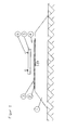
- FIG. 1 Construction of the track bed
- the protective layer is created with the help of a commercially available ballast cleaning machine, which, compared with the planum improvement machines required for gravel-sand mixtures, causes a significantly lower capital expenditure.
- the ballast cleaning machine is merely supplemented by a nonwoven unwinding device and a compaction plank to produce a level and sufficiently densified ground plane.
- ballast bed cleaning As part of a ballast bed cleaning og Bettungstivsmaschine clears the track ballast below the track grid by means of a Schrapers or chain bar, cleans the old ballast, sifts to small gravel components and reintegrates the thus cleaned track ballast below again under the track grid.
- the track grid is only raised in this process, but otherwise remains in its position.
- the created in this work process of ballast cleaning machine ballast-free space can now be used for the introduction of fleece and plate elements. Within this ballast-free working space, the compaction pile runs ahead in the working direction and produces the required flatness, load capacity and density of the earth.
- the fleece is rolled out to the Erdplanum, with an overlap of both roller conveyors of at least 30 cm takes place in a possible roll change.
- the manual insertion of the plate elements forms the last step within the ballast-free working space before the processed ballast is fed back.
- you can of course realize a gravity-assisted mechanical feed of the plate elements for example in analogy to the supply of track sleepers in the known track-laying machines.
- the protective layer according to the invention tolerates a deviation from the desirable joint-free abutment of the plate elements, so that rectangular plate elements can continue to be used for this purpose. This has an advantageous effect on warehouse logistics.
- the usual work for ballast cleaning measures in terms of lifting and compression stoppers and track stabilization done.
Landscapes
- Engineering & Computer Science (AREA)
- Architecture (AREA)
- Civil Engineering (AREA)
- Structural Engineering (AREA)
- Railway Tracks (AREA)
- Machines For Laying And Maintaining Railways (AREA)
- Packaging Of Machine Parts And Wound Products (AREA)
- Aiming, Guidance, Guns With A Light Source, Armor, Camouflage, And Targets (AREA)
- Train Traffic Observation, Control, And Security (AREA)
- Magnetic Heads (AREA)
- Bipolar Transistors (AREA)
- Laminated Bodies (AREA)
Description
- Die Erfindung betrifft ein Gleisbett mit Bettungskörper, Erdkörper und einer Schutzschicht, welche den Bettungskörper gegen den anstehenden Erdkörper abtrennt sowie aneinanderstoßende plattenförmige Elemente mit hoher Druckbelastbarkeit und geringer Wasseraufnahmefähigkeit bei Langzeitkontakt mit Feuchtigkeit aufweist.
- Seit einigen Jahrzehnten ist es im Oberbau der Eisenbahnen üblich, den aus Gleisschotter aufgebauten Bettungskörper gegen das angrenzende Erdplanum mittels sogenannter Planumsschutzschichten (PSS) abzugrenzen. Dadurch soll der Bettungskörper von den teilweise negativen bodenmechanischen Einflüssen des anstehenden Erdgrundes entkoppelt beziehungsweise die unzureichenden bodenmechanischen Kennwerte des anstehenden Erdgrundes kompensiert werden. Üblicherweise werden PSS in Form von mineralischen Kies-Sand-Gemischen (KSG) mit oder ohne Zugabe von Brechkorn oder Recycling aufgebaut, deren Zusammensetzung und Körnung in Abstimmung mit den im jeweiligen Einzelfall vorliegenden hydrologischen und bodenmechanischen Verhältnissen festgelegt werden muss. Auf jeden Fall weisen diese Mineralstoffgemische eine wasserableitende und tragfähigkeitserhöhende Wirkung auf und schützen somit das Schotterbett vor Staunässe, Frostschäden und ungleichmässigen Setzungen bzw. Hebungen. Als besonders nachteilig wird allgemein empfunden, dass die Stärke der einzubauenden Kiessand-Schichten nicht nur ortsabhängig stark variieren, sondern dass vor allem grosse Mengen an Erdmaterial ausgehoben und abtransportiert, zugleich ebenso grosse Mengen an neu einzubauenden Planumssanden angeliefert werden müssen. Da diese Transportvorgänge üblicherweise nur im Profil des gesperrten Arbeitsgleises erfolgen können, sind sie mit grossem maschinentechnischen Aufwand verbunden.
- Aus
DE 31 47 346 ist es bekannt, Hartschaumplatten als Ersatz für diese aus mineralischen Gemischen aufgebaute PSS auf das schotterfreie Planum aufzubringen und somit eine vergleichbare Wirkung wie bei der "klassischen" PSS zu erzielen. Es hat sich jedoch erwiesen, dass keine hinreichend fugenfreie Verlegung der Hartschaumplatten erzielt werden konnte und damit die von einer solchen Schutzschicht geforderte wasserableitende Wirkung nicht erreichbar war. Zur Erzielung einer besseren Wasserabdichtung schlägtDE 31 47 346 den Einbau zweier übereinanderliegender Schichten aus Hartschaumplatten vor, wobei die Trennfugen dieser beiden Schichten zueinander derart versetzt angeordnet werden sollen. In der Baustellenpraxis hat sich dieser Ansatz jedoch als wenig realitätsbezogen erwiesen. - Die
GB 2 243 108 A - Der Erfindung liegt die Aufgabe zugrunde, ein Gleisbett mit Bettungskörper, Erdkörper und einer Schutzschicht, welche den Bettungskörper gegen den anstehenden Erdkörper abtrennt sowie aneinanderstoßende plattenförmige Elemente mit hoher Druckbelastbarkeit und geringer Wasseraufnahmefähigkeit bei Langzeitkontakt mit Feuchtigkeit aufweist, zu entwickeln, das einen verbesserten Übergangsbereich zwischen einem Bettungskörper mit bzw. einem ohne Schutzschicht gewährleistet. Insbesondere soll die Schutzschicht geeignet sein, bestehende, sanierungsbedürftige Strecken mit einem geringeren Logistik- und Maschineneinsatz als bisher zu ertüchtigen. Neben der Ableitung von Wasser aus dem Schotterbett in die Randentwässerung und dem damit einhergehenden Schutz vor Frostschäden soll zugleich das Tragverhalten des Oberbaus hinsichtlich dynamischer und statischer Lasten aus dem Zugverkehr verbessert werden. Die Schutzschicht soll in einem kontinuierlichen Umbauverfahren mit hoher Vortriebsleistung einbaubar sein. Dabei ist anzustreben, dass keine neu zu konstruierenden, kapitalintensiven Baumaschinen erforderlich werden, sondern alle erforderlichen Leistungen weitestgehend mit dem vorhandenen Maschinenpark erbringbar sein sollten. Der Einbau dieser neuen Schutzschicht soll zudem witterungsunabhängiger als bei den Tragschichten aus Kies-Sand-Gemischen sein.
- Diese Aufgabe wird in Verbindung mit dem Oberbegriff des Patentanspruches 1 erfindungsgemäß dadurch gelöst, dass die Stärke der plattenförmigen Elemente im Übergangsbereich zwischen einem mit den plattenförmigen Elementen und der Vliesschicht ausgeführten Bettungskörper und einem ohne Planumsschutzschicht ausgeführten Bettungskörper über eine Länge von mindestens 20 Meter kontinuierlich abnimmt und die Mindeststärke eines Elementes im Schlussbereich des Überganges noch mindestens 0,04 Meter beträgt. Dadurch wird erreicht, dass sowohl die Tragfähigkeit des Unterbaus im Übergangsbereich gewährleistet bleibt, gleichzeitig aber auch trotz unterschiedlicher Elastizitätsmoduli zwischen den beiden Bettungskörpern gleichmäßige Fahreigenschaften für die Züge sichergestellt werden. Ein mit plattenförmigen Elementen und Vliesschicht ausgeführtes System kann nicht nur den Oberbau zuverlässig entwässern, sondern auch die durch Eigengewicht des Oberbaus sowie aus dem Zugverkehr resultierenden Lasten zuverlässig und schadensfrei aufnehmen. Die bevorzugte Ausführung der plattenförmigen Elemente aus Hartschaum bietet zusätzlich die Vorteile einer sehr geringen Wärmeleitfähigkeit, eines hohen Elastizitätsmoduls, günstiger Bruchspannungsverhältnisse sowie eines geringen Eigengewichtes, wodurch auch ein manuelles Handling der Plattenelemente möglich wird. Eine Falzung der Hartschaumplatten gewährleistet eine ausreichend formschlüssige Verbindung jeweils zweier Elemente.
- Gemäss einer vorteilhaften Ausgestaltung des erfindungsgemäßen Gedankens entspricht die Breite der Schutzschicht in Querrichtung zur Gleislängsachse mindestens einem Betrag B, wobei B gemäss der Beziehung B = 2*y + SB ermittelt wird. Hierbei entspricht die Größe y dem vertikalen Abstand zwischen der Oberkante der Schutzschicht und der Unterkante der auf dem Bettungskörper aufliegenden Gleisschwellen, die Größe SB gibt hingegen den in Querrichtung zur Gleislängsachse gemessenen Abstand beider Köpfe einer Gleisschwelle an. Dadurch ist gewährleistet, dass die Schutzschicht unabhängig von ihrer vertikalen Einbauposition stets den relevanten Lastausbreitungsbereich abdeckt.
- Gemäss einer bevorzugten Ausführungsform sind die plattenförmigen Elemente aus Hartschaum, insbesondere extrudiertem Polystyrol (z.B. X-PS-G), aufgebaut.
- Desweiteren ist es sinnvoll, wenn Werkstoff, vertikale Stärke und Grundfläche eines Einzelkörpers dieser plattenförmigen Elemente in Abhängigkeit von den bodenmechanischen Kennwerten des anstehenden Erdkörpers derart dimensioniert sind, dass auf der Oberfläche der eingebauten Schutzschicht Verformungsmoduli von Evd ≥ 45 MN/m2 oder Ev2 ≥ 100 MN/m2 bei einem Verdichtungsgrad von Dpr = 100 % erreicht werden.
- Gemäss einer bevorzugten Ausführungsform ist die Vliesschicht aus Polypropylen ausgeführt und weist ein Flächengewicht von mindestens 400 g/m2 auf. Ebenso ist es noch vorteilhaft, wenn die Vliesschicht bei einer gegebenen Auflast von 2 kN mit einer Mindeststärke von 3 mm ausgeführt ist. Durch diese Materialeigenschaften übt das Vlies eine kapillarbrechende Wirkung aus. Dies ist sinnvoll, damit sowohl das durch die Stösse zwischen den plattenförmigen Elementen eindringende Sickerwasser als auch das durch den Porenwasserüberdruck nach oben steigende Wasser durch das Vlies zuverlässig in die Randentwässerung geführt wird und eine Wasserdurchdringung der Schutzschicht verhindert wird.
- Der Erfindungsgedanke wird in nachfolgendem Ausführungsbeispiel visualisiert. Es zeigt in Prinzipdarstellung
Figur 1 Aufbau des Gleisbetts - Im Vorfeld des Einbaus des erfindungsgemäßen Gleisbetts muss zunächst durch Baugrund-Untersuchungen abgesichert sein, dass im Erdplanum grobkörniger beziehungsweise gemischt- und feinkörniger Boden ansteht, der auf Verformungsmoduli von Evd ≥ 35 MN/m2 oder Ev2 ≥ 45 MN/m2 bei einem Verdichtungsgrad von Dpr = 97 % gebracht werden kann bzw. diese bereits aufweist.
Die Erstellung der Schutzschicht erfolgt mit Hilfe einer handelsüblichen Bettungsreinigungsmaschine, die im Vergleich zu den bei Kies-Sand-Gemischen erforderlichen Planumsverbesserungsmaschinen einen deutlich niedrigeren Kapitalaufwand verursacht. Die Bettungsreinigungsmaschine wird lediglich um eine Abrollvorrichtung für das Vlies sowie eine Verdichtungsbohle zur Herstellung eines ebenen und ausreichend verdichteten Erdplanums ergänzt.
Im Zuge einer Schotterbettreinigung räumt o.g. Bettungsreinigungsmaschine den Gleisschotter unterhalb des Gleisrostes mittels eines Schrapers oder Kettenbalkens aus, reinigt den Altschotter, siebt zu kleine Schotterbestandteile aus und baut den derart gereinigten Gleisschotter nachfolgend wieder unter dem Gleisrost ein. Der Gleisrost wird bei diesem Vorgang lediglich angehoben, verbleibt jedoch ansonsten in seiner Lage. Der bei diesem Arbeitsprozess von der Bettungsreinigungsmaschine geschaffene schotterfreie Raum kann nun auch zum Einbringen von Vlies und Plattenelementen genutzt werden. Innerhalb dieses schotterfreien Arbeitsraumes läuft die Verdichtungsbohle in Arbeitsrichtung voraus und stellt die geforderte Ebenflächigkeit, Tragfähigkeit und Dichte des Erdplanums her. Von der anschließenden Abrollvorrichtung wird das Vlies auf das Erdplanum ausgerollt, wobei bei einem allfälligen Rollenwechsel eine Überlappung beider Rollenbahnen von mindestens 30 cm erfolgt. Das manuelle Einlegen der Plattenelemente bildet innerhalb des schotterfreien Arbeitsraumes den letzten Arbeitsschritt, bevor der aufbereitete Schotter wieder zugeführt wird. Alternativ lässt sich natürlich eine schwerkraftunterstütze mechanische Zuführung der Plattenelemente realisieren, beispielsweise in Analogie zur Zuführung von Gleisschwellen bei den bekannten Gleisumbaumaschinen. In Bogenradien bis zu 250 m toleriert die erfindungsgemäße Schutzschicht ein Abweichen von dem an sich wünschenswerten fugenfreien Aneinanderstoßen der Plattenelemente, so dass hierfür weiterhin rechteckige Plattenelemente verwendet werden können. Die wirkt sich vorteilhaft auf die Lagerlogistik aus. Nach Einbau der erfindungsgemäßen Schutzschicht erfolgen die für Bettungsreinigungsmaßnahmen üblichen Arbeiten hinsichtlich Hebe- und Verdichtungsstopfugen sowie Gleisstabilisierung. -
- 1
- Erdkörper
- 2
- Vlieswerkstoff aus Polypropylen
- 3
- plattenförmiges Element
- 4
- Bettungskörper aus Gleisschotter
- 5
- Gleisschwelle
- 6
- Schiene
Claims (6)
- Gleisbett mit Bettungskörper (4), Erdkörper (1) und einer Schutzschicht , welche den Bettungskörper gegen den anstehenden Erdkörper (1) abtrennt sowie aneinanderstoßende plattenförmige Elemente (3) mit hoher Druckbelastbarkeit und geringer Wasseraufnahmefähigkeit bei Langzeitkontakt mit Feuchtigkeit sowie eine zwischen dem anstehenden Erdkörper und den plattenförmigen Elementen angeordnete Vliesschicht (2) aufweist,
dadurch gekennzeichnet,
dass die Stärke der plattenförmigen Elemente (3) im Übergangsbereich zwischen einem mit den plattenförmigen Elementen und der Vliesschicht ausgeführten Bettungskörper und einem ohne Planumsschutzschicht ausgeführten Bettungskörper über eine Länge von mindestens 20 Meter kontinuierlich abnimmt und die Mindeststärke eines Elementes im Schlussbereich des Überganges noch mindestens 0,04 Meter beträgt. - Gleisbett mit Bettungskörper (4), Erdkörper (1) und einer Schutzschicht nach Anspruch 1, dadurch gekennzeichnet, dass die Breite der Schutzschicht in Querrichtung zur Gleislängsachse mindestens einem Betrag B entspricht, wobei B gemäss der Beziehung B = 2*y + SB ermittelt wird, die Grösse y dem vertikalen Abstand zwischen der Oberkante der Schutzschicht und der Unterkante der auf dem Bettungskörper aufliegenden Gleisschwellen (5) entspricht sowie SB den in Querrichtung zur Gleislängsachse gemessenen Abstand beider Köpfe einer Gleisschwelle angibt.
- Gleisbett mit Bettungskörper (4), Erdkörper (1) und einer Schutzschicht nach mindestens einem der Ansprüche 1 bis 2, dadurch gekennzeichnet, dass die plattenförmigen Elemente (3) aus Hartschaum, insbesondere extrudiertem Polystyrol, aufgebaut sind.
- Gleisbett mit Bettungskörper (4), Erdkörper (1) und einer Schutzschicht nach mindestens einem der Ansprüche 1 bis 3, dadurch gekennzeichnet, dass Werkstoff, vertikale Stärke und Grundfläche eines Einzelkörpers der plattenförmigen Elemente (3) in Abhängigkeit von den bodenmechanischen Kennwerten des anstehenden Erdkörpers derart dimensioniert sind, dass auf der Oberfläche der eingebauten Schutzschicht Verformungsmoduli von Evd ≥ 45 MN/m2 oder Ev2 ≥ 100 MN/m2 bei einem Verdichtungsgrad von Dpr = 100 % erreicht werden.
- Gleisbett mit Bettungskörper (4), Erdkörper (1) und einer Schutzschicht nach mindestens einem der Ansprüche 1 bis 4, dadurch gekennzeichnet, dass die Vliesschicht (2) aus Polypropylen ausgeführt ist und ein Flächengewicht von mindestens 400 g/m2 aufweist.
- Gleisbett mit Bettungskörper (4), Erdkörper (1) und einer Schutzschicht nach mindestens einem der Ansprüche 1 bis 5, dadurch gekennzeichnet, dass die Vliesschicht (2) bei einer gegebenen Auflast von 2 kN mit einer Mindeststärke von 3 mm ausgeführt ist.
Priority Applications (1)
| Application Number | Priority Date | Filing Date | Title |
|---|---|---|---|
| PL04017565T PL1512792T3 (pl) | 2003-09-03 | 2004-07-24 | Warstwa ochronna dla podtorza trasy torowej |
Applications Claiming Priority (2)
| Application Number | Priority Date | Filing Date | Title |
|---|---|---|---|
| DE20313800U | 2003-09-03 | ||
| DE20313800U DE20313800U1 (de) | 2003-09-03 | 2003-09-03 | Schutzschicht für den Bettungskörper eines Gleisfahrweges |
Publications (3)
| Publication Number | Publication Date |
|---|---|
| EP1512792A2 EP1512792A2 (de) | 2005-03-09 |
| EP1512792A3 EP1512792A3 (de) | 2005-05-11 |
| EP1512792B1 true EP1512792B1 (de) | 2010-01-20 |
Family
ID=29558155
Family Applications (1)
| Application Number | Title | Priority Date | Filing Date |
|---|---|---|---|
| EP04017565A Expired - Lifetime EP1512792B1 (de) | 2003-09-03 | 2004-07-24 | Schutzschicht für den Bettungskörper eines Gleisfahrweges |
Country Status (4)
| Country | Link |
|---|---|
| EP (1) | EP1512792B1 (de) |
| AT (1) | ATE455905T1 (de) |
| DE (3) | DE20313800U1 (de) |
| PL (1) | PL1512792T3 (de) |
Families Citing this family (2)
| Publication number | Priority date | Publication date | Assignee | Title |
|---|---|---|---|---|
| CN101979766B (zh) * | 2010-10-21 | 2012-07-11 | 中铁第四勘察设计院集团有限公司 | 高速铁路红黏土路堑基床结构 |
| DE102012105983A1 (de) * | 2012-07-04 | 2014-01-09 | Hering Bau Gmbh & Co. Kg | Akustische Abschirmeinheit und deren Aufbau |
Citations (1)
| Publication number | Priority date | Publication date | Assignee | Title |
|---|---|---|---|---|
| GB2243108A (en) * | 1990-02-14 | 1991-10-23 | Ian Thomas Smith | A component for use in railway track construction |
Family Cites Families (4)
| Publication number | Priority date | Publication date | Assignee | Title |
|---|---|---|---|---|
| GB339520A (en) * | 1929-12-30 | 1930-12-11 | Trinidad Deutsche Oel Und Asph | Method of constructing railway embankments |
| US3587964A (en) * | 1969-04-18 | 1971-06-28 | Meadows W R Inc | Protective course for bridge deck |
| AT370151B (de) * | 1981-03-04 | 1983-03-10 | Plasser Bahnbaumasch Franz | Schotterbett-reinigungsmaschine und hartschaumplatten-verlegung |
| DE3524719A1 (de) * | 1985-07-11 | 1987-01-15 | Phoenix Ag | Schutzschicht fuer elastische gleisbettmatte |
-
2003
- 2003-09-03 DE DE20313800U patent/DE20313800U1/de not_active Expired - Lifetime
-
2004
- 2004-04-13 DE DE202004005761U patent/DE202004005761U1/de not_active Expired - Lifetime
- 2004-07-24 DE DE502004010662T patent/DE502004010662D1/de not_active Expired - Lifetime
- 2004-07-24 EP EP04017565A patent/EP1512792B1/de not_active Expired - Lifetime
- 2004-07-24 PL PL04017565T patent/PL1512792T3/pl unknown
- 2004-07-24 AT AT04017565T patent/ATE455905T1/de active
Patent Citations (1)
| Publication number | Priority date | Publication date | Assignee | Title |
|---|---|---|---|---|
| GB2243108A (en) * | 1990-02-14 | 1991-10-23 | Ian Thomas Smith | A component for use in railway track construction |
Also Published As
| Publication number | Publication date |
|---|---|
| DE202004005761U1 (de) | 2004-08-19 |
| PL1512792T3 (pl) | 2010-06-30 |
| ATE455905T1 (de) | 2010-02-15 |
| EP1512792A2 (de) | 2005-03-09 |
| DE20313800U1 (de) | 2003-11-13 |
| DE502004010662D1 (de) | 2010-03-11 |
| EP1512792A3 (de) | 2005-05-11 |
Similar Documents
| Publication | Publication Date | Title |
|---|---|---|
| EP2920366B1 (de) | Schienengebundenes transportsystem für eine gleisbaumaschine | |
| EP1619305B1 (de) | Teilverschäumter Gleisoberbau und Verfahren für dessen Herstellung | |
| DE2306428B2 (de) | Gleisoberbau und verfahren zu dessen herstellung | |
| AT391499B (de) | Eisenbahnoberbau, insbesondere fuer schienenfahrzeuge mit sehr hohen fahrgeschwindigkeiten | |
| EP0516612A1 (de) | Schotterloser Oberbau mit Schienen | |
| AT410329B (de) | Schotterloser oberbau | |
| CH687031A5 (de) | Verfahren zur Erstellung bzw. Sanierung eines laengs eines Bahndamms verlaufenden Randweges. | |
| EP3997270B1 (de) | Schotter-kunststoff-verbundkörper | |
| EP1512792B1 (de) | Schutzschicht für den Bettungskörper eines Gleisfahrweges | |
| WO2012130425A2 (de) | Fahrbahnweg für schienengebundene fahrzeuge sowie fahrbahnunterstützung für einen solchen fahrbahnweg | |
| EP1576240B1 (de) | Verfahren zum herstellen einer festen fahrbahn und fahrweg | |
| DE102012009284B4 (de) | Verfahren zur Sanierung einer festen Fahrbahn / Verfestigte Schotterbahn | |
| DE19848655B4 (de) | Sanierung von Festen Fahrbahnen | |
| DE4407747C2 (de) | Gleis für den schienengeleiteten Verkehr sowie Verfahren zum Ertüchtigen von Gleisen | |
| DE2901283A1 (de) | Schotterloser oberbau fuer schienengebundene fahrzeuge | |
| DE3803120C2 (de) | ||
| DE102008044675B4 (de) | Erschütterungsschutz für einen Gleisoberbau und Herstellungsverfahren dafür | |
| AT413553B (de) | Gleis für schienenfahrzeuge sowie verfahren zum herstellen eines gleises | |
| DE69916641T2 (de) | Verbesserungen an oder in bezug auf bahnanlagen für schienenfahrzeuge | |
| DE1658308A1 (de) | Schienenweg | |
| DE9422256U1 (de) | Gleis für den schienengeleiteten Verkehr | |
| DE102005027758B3 (de) | Verfahren für die Erneuerung eines mittels Schwellen in fester Fahrbahn verlegten Gleises sowie Heberichtschwelle zur Verwendung in dem Verfahren | |
| DE102021127502A1 (de) | Gleis für spurgeführte Schienenfahrzeuge und Verfahren zu dessen Errichtung | |
| DE102024119728A1 (de) | Verfahren zur Sanierung und Stabilisierung eines Gleisbetts | |
| AT907U1 (de) | Gleisoberbau mit schwellen und zwischenlage für einen gleisoberbau |
Legal Events
| Date | Code | Title | Description |
|---|---|---|---|
| PUAI | Public reference made under article 153(3) epc to a published international application that has entered the european phase |
Free format text: ORIGINAL CODE: 0009012 |
|
| AK | Designated contracting states |
Kind code of ref document: A2 Designated state(s): AT BE BG CH CY CZ DE DK EE ES FI FR GB GR HU IE IT LI LU MC NL PL PT RO SE SI SK TR |
|
| AX | Request for extension of the european patent |
Extension state: AL HR LT LV MK |
|
| PUAL | Search report despatched |
Free format text: ORIGINAL CODE: 0009013 |
|
| AK | Designated contracting states |
Kind code of ref document: A3 Designated state(s): AT BE BG CH CY CZ DE DK EE ES FI FR GB GR HU IE IT LI LU MC NL PL PT RO SE SI SK TR |
|
| AX | Request for extension of the european patent |
Extension state: AL HR LT LV MK |
|
| 17P | Request for examination filed |
Effective date: 20050805 |
|
| AKX | Designation fees paid |
Designated state(s): AT BE BG CH CY CZ DE DK EE ES FI FR GB GR HU IE IT LI LU MC NL PL PT RO SE SI SK TR |
|
| 17Q | First examination report despatched |
Effective date: 20070214 |
|
| GRAP | Despatch of communication of intention to grant a patent |
Free format text: ORIGINAL CODE: EPIDOSNIGR1 |
|
| GRAS | Grant fee paid |
Free format text: ORIGINAL CODE: EPIDOSNIGR3 |
|
| GRAA | (expected) grant |
Free format text: ORIGINAL CODE: 0009210 |
|
| AK | Designated contracting states |
Kind code of ref document: B1 Designated state(s): AT BE BG CH CY CZ DE DK EE ES FI FR GB GR HU IE IT LI LU MC NL PL PT RO SE SI SK TR |
|
| REG | Reference to a national code |
Ref country code: GB Ref legal event code: FG4D Free format text: NOT ENGLISH |
|
| REG | Reference to a national code |
Ref country code: CH Ref legal event code: NV Representative=s name: RIEDERER HASLER & PARTNER PATENTANWAELTE AG Ref country code: CH Ref legal event code: EP |
|
| REG | Reference to a national code |
Ref country code: IE Ref legal event code: FG4D |
|
| REF | Corresponds to: |
Ref document number: 502004010662 Country of ref document: DE Date of ref document: 20100311 Kind code of ref document: P |
|
| PG25 | Lapsed in a contracting state [announced via postgrant information from national office to epo] |
Ref country code: PT Free format text: LAPSE BECAUSE OF FAILURE TO SUBMIT A TRANSLATION OF THE DESCRIPTION OR TO PAY THE FEE WITHIN THE PRESCRIBED TIME-LIMIT Effective date: 20100520 Ref country code: ES Free format text: LAPSE BECAUSE OF FAILURE TO SUBMIT A TRANSLATION OF THE DESCRIPTION OR TO PAY THE FEE WITHIN THE PRESCRIBED TIME-LIMIT Effective date: 20100501 |
|
| REG | Reference to a national code |
Ref country code: IE Ref legal event code: FD4D |
|
| PG25 | Lapsed in a contracting state [announced via postgrant information from national office to epo] |
Ref country code: SI Free format text: LAPSE BECAUSE OF FAILURE TO SUBMIT A TRANSLATION OF THE DESCRIPTION OR TO PAY THE FEE WITHIN THE PRESCRIBED TIME-LIMIT Effective date: 20100120 Ref country code: FI Free format text: LAPSE BECAUSE OF FAILURE TO SUBMIT A TRANSLATION OF THE DESCRIPTION OR TO PAY THE FEE WITHIN THE PRESCRIBED TIME-LIMIT Effective date: 20100120 |
|
| PGFP | Annual fee paid to national office [announced via postgrant information from national office to epo] |
Ref country code: PL Payment date: 20100531 Year of fee payment: 7 |
|
| PG25 | Lapsed in a contracting state [announced via postgrant information from national office to epo] |
Ref country code: IE Free format text: LAPSE BECAUSE OF FAILURE TO SUBMIT A TRANSLATION OF THE DESCRIPTION OR TO PAY THE FEE WITHIN THE PRESCRIBED TIME-LIMIT Effective date: 20100120 Ref country code: EE Free format text: LAPSE BECAUSE OF FAILURE TO SUBMIT A TRANSLATION OF THE DESCRIPTION OR TO PAY THE FEE WITHIN THE PRESCRIBED TIME-LIMIT Effective date: 20100120 Ref country code: GR Free format text: LAPSE BECAUSE OF FAILURE TO SUBMIT A TRANSLATION OF THE DESCRIPTION OR TO PAY THE FEE WITHIN THE PRESCRIBED TIME-LIMIT Effective date: 20100421 Ref country code: RO Free format text: LAPSE BECAUSE OF FAILURE TO SUBMIT A TRANSLATION OF THE DESCRIPTION OR TO PAY THE FEE WITHIN THE PRESCRIBED TIME-LIMIT Effective date: 20100120 Ref country code: SE Free format text: LAPSE BECAUSE OF FAILURE TO SUBMIT A TRANSLATION OF THE DESCRIPTION OR TO PAY THE FEE WITHIN THE PRESCRIBED TIME-LIMIT Effective date: 20100120 Ref country code: CY Free format text: LAPSE BECAUSE OF FAILURE TO SUBMIT A TRANSLATION OF THE DESCRIPTION OR TO PAY THE FEE WITHIN THE PRESCRIBED TIME-LIMIT Effective date: 20100120 |
|
| PLBE | No opposition filed within time limit |
Free format text: ORIGINAL CODE: 0009261 |
|
| STAA | Information on the status of an ep patent application or granted ep patent |
Free format text: STATUS: NO OPPOSITION FILED WITHIN TIME LIMIT |
|
| PG25 | Lapsed in a contracting state [announced via postgrant information from national office to epo] |
Ref country code: SK Free format text: LAPSE BECAUSE OF FAILURE TO SUBMIT A TRANSLATION OF THE DESCRIPTION OR TO PAY THE FEE WITHIN THE PRESCRIBED TIME-LIMIT Effective date: 20100120 Ref country code: BG Free format text: LAPSE BECAUSE OF FAILURE TO SUBMIT A TRANSLATION OF THE DESCRIPTION OR TO PAY THE FEE WITHIN THE PRESCRIBED TIME-LIMIT Effective date: 20100420 |
|
| PGFP | Annual fee paid to national office [announced via postgrant information from national office to epo] |
Ref country code: CZ Payment date: 20100714 Year of fee payment: 7 |
|
| 26N | No opposition filed |
Effective date: 20101021 |
|
| BERE | Be: lapsed |
Owner name: DB NETZ A.G. Effective date: 20100731 |
|
| PG25 | Lapsed in a contracting state [announced via postgrant information from national office to epo] |
Ref country code: DK Free format text: LAPSE BECAUSE OF FAILURE TO SUBMIT A TRANSLATION OF THE DESCRIPTION OR TO PAY THE FEE WITHIN THE PRESCRIBED TIME-LIMIT Effective date: 20100120 |
|
| PG25 | Lapsed in a contracting state [announced via postgrant information from national office to epo] |
Ref country code: MC Free format text: LAPSE BECAUSE OF NON-PAYMENT OF DUE FEES Effective date: 20100731 |
|
| GBPC | Gb: european patent ceased through non-payment of renewal fee |
Effective date: 20100724 |
|
| PG25 | Lapsed in a contracting state [announced via postgrant information from national office to epo] |
Ref country code: IT Free format text: LAPSE BECAUSE OF FAILURE TO SUBMIT A TRANSLATION OF THE DESCRIPTION OR TO PAY THE FEE WITHIN THE PRESCRIBED TIME-LIMIT Effective date: 20100120 |
|
| REG | Reference to a national code |
Ref country code: FR Ref legal event code: ST Effective date: 20110331 |
|
| PG25 | Lapsed in a contracting state [announced via postgrant information from national office to epo] |
Ref country code: FR Free format text: LAPSE BECAUSE OF NON-PAYMENT OF DUE FEES Effective date: 20100802 |
|
| PG25 | Lapsed in a contracting state [announced via postgrant information from national office to epo] |
Ref country code: BE Free format text: LAPSE BECAUSE OF NON-PAYMENT OF DUE FEES Effective date: 20100731 |
|
| PG25 | Lapsed in a contracting state [announced via postgrant information from national office to epo] |
Ref country code: GB Free format text: LAPSE BECAUSE OF NON-PAYMENT OF DUE FEES Effective date: 20100724 |
|
| PGFP | Annual fee paid to national office [announced via postgrant information from national office to epo] |
Ref country code: LU Payment date: 20110722 Year of fee payment: 8 |
|
| PGFP | Annual fee paid to national office [announced via postgrant information from national office to epo] |
Ref country code: CH Payment date: 20110725 Year of fee payment: 8 |
|
| PGFP | Annual fee paid to national office [announced via postgrant information from national office to epo] |
Ref country code: DE Payment date: 20110926 Year of fee payment: 8 Ref country code: AT Payment date: 20110720 Year of fee payment: 8 |
|
| PGFP | Annual fee paid to national office [announced via postgrant information from national office to epo] |
Ref country code: NL Payment date: 20110725 Year of fee payment: 8 |
|
| PG25 | Lapsed in a contracting state [announced via postgrant information from national office to epo] |
Ref country code: CZ Free format text: LAPSE BECAUSE OF NON-PAYMENT OF DUE FEES Effective date: 20110724 |
|
| PG25 | Lapsed in a contracting state [announced via postgrant information from national office to epo] |
Ref country code: HU Free format text: LAPSE BECAUSE OF FAILURE TO SUBMIT A TRANSLATION OF THE DESCRIPTION OR TO PAY THE FEE WITHIN THE PRESCRIBED TIME-LIMIT Effective date: 20100721 |
|
| PG25 | Lapsed in a contracting state [announced via postgrant information from national office to epo] |
Ref country code: TR Free format text: LAPSE BECAUSE OF FAILURE TO SUBMIT A TRANSLATION OF THE DESCRIPTION OR TO PAY THE FEE WITHIN THE PRESCRIBED TIME-LIMIT Effective date: 20100120 Ref country code: PL Free format text: LAPSE BECAUSE OF NON-PAYMENT OF DUE FEES Effective date: 20110724 |
|
| REG | Reference to a national code |
Ref country code: PL Ref legal event code: LAPE |
|
| REG | Reference to a national code |
Ref country code: NL Ref legal event code: V1 Effective date: 20130201 |
|
| REG | Reference to a national code |
Ref country code: CH Ref legal event code: PL |
|
| REG | Reference to a national code |
Ref country code: AT Ref legal event code: MM01 Ref document number: 455905 Country of ref document: AT Kind code of ref document: T Effective date: 20120724 |
|
| PG25 | Lapsed in a contracting state [announced via postgrant information from national office to epo] |
Ref country code: DE Free format text: LAPSE BECAUSE OF NON-PAYMENT OF DUE FEES Effective date: 20130201 Ref country code: NL Free format text: LAPSE BECAUSE OF NON-PAYMENT OF DUE FEES Effective date: 20130201 Ref country code: LI Free format text: LAPSE BECAUSE OF NON-PAYMENT OF DUE FEES Effective date: 20120731 Ref country code: CH Free format text: LAPSE BECAUSE OF NON-PAYMENT OF DUE FEES Effective date: 20120731 |
|
| PG25 | Lapsed in a contracting state [announced via postgrant information from national office to epo] |
Ref country code: AT Free format text: LAPSE BECAUSE OF NON-PAYMENT OF DUE FEES Effective date: 20120724 |
|
| REG | Reference to a national code |
Ref country code: DE Ref legal event code: R119 Ref document number: 502004010662 Country of ref document: DE Effective date: 20130201 |
|
| PG25 | Lapsed in a contracting state [announced via postgrant information from national office to epo] |
Ref country code: LU Free format text: LAPSE BECAUSE OF NON-PAYMENT OF DUE FEES Effective date: 20120724 |