EP1512596A1 - Pedalstützkonstruktion mit kollisionsschutzmechanismus - Google Patents
Pedalstützkonstruktion mit kollisionsschutzmechanismus Download PDFInfo
- Publication number
- EP1512596A1 EP1512596A1 EP03702656A EP03702656A EP1512596A1 EP 1512596 A1 EP1512596 A1 EP 1512596A1 EP 03702656 A EP03702656 A EP 03702656A EP 03702656 A EP03702656 A EP 03702656A EP 1512596 A1 EP1512596 A1 EP 1512596A1
- Authority
- EP
- European Patent Office
- Prior art keywords
- pedal
- support structure
- structure according
- intermediate device
- joined
- Prior art date
- Legal status (The legal status is an assumption and is not a legal conclusion. Google has not performed a legal analysis and makes no representation as to the accuracy of the status listed.)
- Granted
Links
- 230000007246 mechanism Effects 0.000 title description 13
- 210000003141 lower extremity Anatomy 0.000 description 4
- 230000000694 effects Effects 0.000 description 1
- 230000003116 impacting effect Effects 0.000 description 1
Images


Classifications
-
- G—PHYSICS
- G05—CONTROLLING; REGULATING
- G05G—CONTROL DEVICES OR SYSTEMS INSOFAR AS CHARACTERISED BY MECHANICAL FEATURES ONLY
- G05G1/00—Controlling members, e.g. knobs or handles; Assemblies or arrangements thereof; Indicating position of controlling members
- G05G1/30—Controlling members actuated by foot
- G05G1/32—Controlling members actuated by foot with means to prevent injury
-
- B—PERFORMING OPERATIONS; TRANSPORTING
- B60—VEHICLES IN GENERAL
- B60R—VEHICLES, VEHICLE FITTINGS, OR VEHICLE PARTS, NOT OTHERWISE PROVIDED FOR
- B60R21/00—Arrangements or fittings on vehicles for protecting or preventing injuries to occupants or pedestrians in case of accidents or other traffic risks
- B60R21/02—Occupant safety arrangements or fittings, e.g. crash pads
- B60R21/09—Control elements or operating handles movable from an operative to an out-of-the way position, e.g. pedals, switch knobs, window cranks
-
- B—PERFORMING OPERATIONS; TRANSPORTING
- B60—VEHICLES IN GENERAL
- B60T—VEHICLE BRAKE CONTROL SYSTEMS OR PARTS THEREOF; BRAKE CONTROL SYSTEMS OR PARTS THEREOF, IN GENERAL; ARRANGEMENT OF BRAKING ELEMENTS ON VEHICLES IN GENERAL; PORTABLE DEVICES FOR PREVENTING UNWANTED MOVEMENT OF VEHICLES; VEHICLE MODIFICATIONS TO FACILITATE COOLING OF BRAKES
- B60T7/00—Brake-action initiating means
- B60T7/02—Brake-action initiating means for personal initiation
- B60T7/04—Brake-action initiating means for personal initiation foot actuated
- B60T7/06—Disposition of pedal
- B60T7/065—Disposition of pedal with means to prevent injuries in case of collision
Definitions
- the present invention relates to pedal support structures for vehicles and more specifically to pedal support structures comprising anti-collision safety mechanisms.
- Pedals for vehicles with diverse safety mechanisms activated only in the event of a head-on collision are already known. These mechanisms must safeguard the integrity of the lower extremities of the driver of the vehicle. In order to achieve this, in the event of a collision the pedal must be prevented from moving towards the driver at a magnitude or a speed that is dangerous.
- Pedal structures exist wherein the mechanism is activated when sudden deceleration caused by the impact is detected. Said deceleration causes certain parts to break directly as a result of the inertia generated or is measured by electronic elements that activate the controlled breakage of certain parts.
- pedal structures are based on the distance between the wall where the pedals are secured and an element in the vehicle considered to be deformation-resistant in the accident. In the event of a head-on collision said wall is moved, thus reducing the distance between the wall and the deformation-resistant element. In such cases a mechanism is activated that prevents the pedals from transmitting the energy of the impact. There are various means of achieving this such as breaking the shaft of the pedal, breaking the drive rod to the servo-brake or forcing the pedal to make a negative movement.
- EP 1,110,791 A2 describes a safety mechanism in pedals based on a unit comprising parts that are fitted together and positioned between the deformation-resistant transverse element in the passenger compartment and the wall separating the compartment from the engine.
- the mechanism includes an intermediate device that forces the pedal to move backwards when said wall moves towards the transverse element.
- the object of the invention is to provide a pedal support structure for vehicles that comprises a safety mechanism preventing the pedals from injuring the lower extremities of the driver in the event of a head-on collision, with the result that some of the characteristics of pedal support structures in the prior art are improved upon.
- Vehicles in which the inventive pedal support structure is applied comprise a passenger compartment, a wall, which is disposed in the front part of the passenger compartment, and a deformation-resistant transverse element.
- Said deformation-resistant element usually forms part of the deformation-resistant structure that these vehicles have in order to protect the vehicle's passengers in the event of an accident.
- the shaft of the pedal is connected to the intermediate device and, in the event of a head-on collision, said intermediate device moves the shaft towards the compartment under the force of the deformation-resistant transverse element on said intermediate device. Consequently, the movement of the shaft of the pedal towards the compartment, and, therefore, towards the driver, forces the pedal to tilt towards the compartment wall, forcing the shoe on said pedal away from the driver's legs.
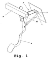
- vehicles in which the inventive pedal support structure is applied comprise a compartment, a wall 2, which is disposed in the front part of the compartment, and a deformation-resistant transverse element 9.
- the support structure comprises a support part 1 which is joined to the above-mentioned wall 2, an intermediate safety device 3 which is connected to said support part 1 and at least one pedal 6 which rotates around a shaft 7.
- the shaft 7 of the pedal 6 is connected to the intermediate device 3 and, in the event of a head-on collision, said intermediate device 3 moves the shaft 7 towards the compartment under the force of the deformation-resistant transverse element 9 on said intermediate device 3.
- the inventive pedal support structure comprises breakable elements that immobilise the intermediate device 3 in relation to the support part 1. These elements break in the event of a head-on collision allowing the intermediate device 3 to move in relation to the support part 1, with the shaft 7 of the pedal 6 moving towards the compartment as a result.
- said intermediate device 3 comprises an extension 8 which faces the deformation-resistant transverse element 9, with said deformation-resistant transverse element 9 slowing the advance of said extension 8 in the event of a head-on collision and thus causing the intermediate device 3 to move in relation to the support part 1.
- the intermediate device 3 comprises a rocker 30 which includes the extension 8.
- the rocker 30 is joined to the support part 1 by a rotating transverse connection 4.
- the breakable elements comprise a fixed connection 5 between the rocker 30 and the support part 1.
- said breakable elements may comprise a wall connected to support part 1 that secures said rocker 30.
- the proportion in which the pedal 6 moves away from the driver as the wall 2 advances is determined on the one hand by the distance between the shaft 7 of the pedal 6 and the rotating connection 4, and on the other by the distance between said rotating connection 4 and the point of contact between the rocker 3 and the deformation-resistant transverse element 9.
- the shaft 7 of the pedal 6 advances towards the driver in greater magnitude than the connection point between the pedal 6 and the rod 10, causing the shoe 11 on the pedal 6 to effectively move back.
- the effective movement of the shoe 11 during the collision can be reduced in relation to its initial position so that it remains virtually immobile.
- the extension 8 on the rocker 3 comprises a pin 12, and the deformation-resistant transverse element 9 has a slot 13, with said pin 12 being housed in said slot 13.
- this combination of a pin 12 and a slot 13 can also be used.
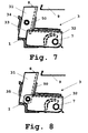
- the intermediate device 3 comprises a first part 31 that includes the extension 8 and a second part 32 to which the shaft 7 of the pedal 6 is connected. This second part 32 is in contact with said first part 31.
- the first part 31 comprises a flange 33 that secures the second part 32, with said first part 31 joined to the support part 1 by a rotating transverse connection 34.
- the intermediate device of which is detailed in figure 8 the first part 31 and the second part 32 are connected by a rotating transverse connection 35.
- the operating mode is the same as in the embodiment described previously.
- the breakable elements may comprise a wall 50 joined to the support part 1. In figures 5 to 8 said wall 50 secures the first part 31.
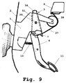
- the intermediate device 3 comprises a rocker 36 connected to the support part 1 by a rotating transverse connection 39.
- Said rocker 36 is connected to the deformation-resistant transverse element 9 by a cable 37 supported on a pulley 38 joined to the support part 1.
- the breakable elements comprise a wall 51 connected to the support part 1. Said wall 51 secures the rocker 36.
- said breakable elements may comprise a fixed connection between the rocker 36 and the support part 1, as shown in the embodiment in figures 1 to 3.
Landscapes
- Engineering & Computer Science (AREA)
- Mechanical Engineering (AREA)
- Physics & Mathematics (AREA)
- General Physics & Mathematics (AREA)
- Automation & Control Theory (AREA)
- Transportation (AREA)
- Mechanical Control Devices (AREA)
- Body Structure For Vehicles (AREA)
Applications Claiming Priority (3)
| Application Number | Priority Date | Filing Date | Title |
|---|---|---|---|
| ES200200134 | 2002-01-23 | ||
| ES200200134A ES2192473B1 (es) | 2002-01-23 | 2002-01-23 | Estructura soporte de pedales con mecanismo de seguridad ante colisiones frontales. |
| PCT/ES2003/000016 WO2003062029A1 (es) | 2002-01-23 | 2003-01-15 | Estructura soporte de pedales con mecanismo de seguridad ante colisiones frontales |
Publications (2)
| Publication Number | Publication Date |
|---|---|
| EP1512596A1 true EP1512596A1 (de) | 2005-03-09 |
| EP1512596B1 EP1512596B1 (de) | 2011-12-28 |
Family
ID=27589309
Family Applications (1)
| Application Number | Title | Priority Date | Filing Date |
|---|---|---|---|
| EP03702656A Expired - Lifetime EP1512596B1 (de) | 2002-01-23 | 2003-01-15 | Fahrzeug mit einer pedalstützkonstruktion mit kollisionsschutzmechanismus |
Country Status (4)
| Country | Link |
|---|---|
| EP (1) | EP1512596B1 (de) |
| AT (1) | ATE538980T1 (de) |
| ES (1) | ES2192473B1 (de) |
| WO (1) | WO2003062029A1 (de) |
Cited By (2)
| Publication number | Priority date | Publication date | Assignee | Title |
|---|---|---|---|---|
| EP1813488A3 (de) * | 2006-01-31 | 2009-01-07 | Fuji Jukogyo Kabushiki Kaisha | Pedal-Verschiebesteuervorrichtung für ein Fahrzeug |
| JP2020095373A (ja) * | 2018-12-11 | 2020-06-18 | 豊田鉄工株式会社 | 車両用操作ペダル装置 |
Families Citing this family (5)
| Publication number | Priority date | Publication date | Assignee | Title |
|---|---|---|---|---|
| ITTO20040358A1 (it) * | 2004-05-27 | 2004-08-27 | S I V Spa | Pedale per autoveicolo provvisto di dispositivo di collassamento |
| BR112012019497A2 (pt) | 2010-02-04 | 2017-06-27 | Ksr Tech Co | aparelho de freio eletromecanico |
| US8806976B2 (en) | 2010-02-04 | 2014-08-19 | Ksr Technologies Co. | Brake pedal assembly having non-contacting sensor |
| JP5685470B2 (ja) | 2011-03-31 | 2015-03-18 | 富士重工業株式会社 | 車両用操作ペダル構造 |
| US8899130B2 (en) | 2011-06-28 | 2014-12-02 | Autoline Industries Indiana, Llc | Vehicle pedal system |
Family Cites Families (5)
| Publication number | Priority date | Publication date | Assignee | Title |
|---|---|---|---|---|
| IT1284785B1 (it) * | 1996-09-10 | 1998-05-21 | Siv S P A | Sistema per liberare il pedale del freno in caso di collisione. |
| US6089119A (en) * | 1998-03-23 | 2000-07-18 | Bosch Systemes De Freinage | Motor vehicle pedal arrangement |
| JP3792465B2 (ja) * | 1999-07-02 | 2006-07-05 | 株式会社エフテック | 自動車のブレーキペダル装置 |
| JP3804372B2 (ja) * | 1999-12-01 | 2006-08-02 | マツダ株式会社 | 自動車のペダル支持構造 |
| GB9930601D0 (en) | 1999-12-24 | 2000-02-16 | Ksr Automotive Limited | Vehicle pedal box |
-
2002
- 2002-01-23 ES ES200200134A patent/ES2192473B1/es not_active Expired - Fee Related
-
2003
- 2003-01-15 AT AT03702656T patent/ATE538980T1/de active
- 2003-01-15 EP EP03702656A patent/EP1512596B1/de not_active Expired - Lifetime
- 2003-01-15 WO PCT/ES2003/000016 patent/WO2003062029A1/es not_active Ceased
Non-Patent Citations (1)
| Title |
|---|
| See references of WO03062029A1 * |
Cited By (6)
| Publication number | Priority date | Publication date | Assignee | Title |
|---|---|---|---|---|
| EP1813488A3 (de) * | 2006-01-31 | 2009-01-07 | Fuji Jukogyo Kabushiki Kaisha | Pedal-Verschiebesteuervorrichtung für ein Fahrzeug |
| US8100033B2 (en) | 2006-01-31 | 2012-01-24 | Fuji Jukogyo Kabushiki Kaisha | Vehicle pedal displacement control structure |
| JP2020095373A (ja) * | 2018-12-11 | 2020-06-18 | 豊田鉄工株式会社 | 車両用操作ペダル装置 |
| WO2020121589A1 (ja) * | 2018-12-11 | 2020-06-18 | 豊田鉄工株式会社 | 車両用操作ペダル装置 |
| JP7000300B2 (ja) | 2018-12-11 | 2022-01-19 | 豊田鉄工株式会社 | 車両用操作ペダル装置 |
| US11794704B2 (en) | 2018-12-11 | 2023-10-24 | Toyoda Iron Works Co., Ltd. | Vehicular operation pedal device |
Also Published As
| Publication number | Publication date |
|---|---|
| EP1512596B1 (de) | 2011-12-28 |
| ATE538980T1 (de) | 2012-01-15 |
| WO2003062029A1 (es) | 2003-07-31 |
| ES2192473B1 (es) | 2004-07-01 |
| WO2003062029A8 (es) | 2003-10-23 |
| ES2192473A1 (es) | 2003-10-01 |
Similar Documents
| Publication | Publication Date | Title |
|---|---|---|
| US6786109B2 (en) | Safety device for supporting pedals | |
| JP4138483B2 (ja) | 自動車のペダルレバーを支承するための装置 | |
| US6364046B1 (en) | Method for activation of a safety arrangement in a vehicle | |
| US20100043592A1 (en) | Pedal assembly having a safety device | |
| EP1709505B1 (de) | Pedal-träger | |
| EP1557330A2 (de) | Pedal mit Antikollisionssicherheitsmechanismus | |
| EP1512596A1 (de) | Pedalstützkonstruktion mit kollisionsschutzmechanismus | |
| US8887857B2 (en) | Safety arrangement for vehicle pedal | |
| JP4669509B2 (ja) | 車両における乗員保護手段の制御方法及び乗員保護システム | |
| JP2008514505A (ja) | 安全装置 | |
| DE102005052250A1 (de) | Verfahren und Vorrichtung zur Aktivierung von Insassenschutzsystemen | |
| US8661933B2 (en) | Vehicle brake pedal crash safety device | |
| EP3642083B1 (de) | Pedalanordnung für ein kraftfahrzeug | |
| KR101535015B1 (ko) | 차량용 페달 안전장치 | |
| EP1038720A2 (de) | Pedalgehäuse für Fahrzeug | |
| KR101428228B1 (ko) | 운전자 보호용 페달장치 | |
| EP1980460B1 (de) | Aufprallsicherheitsvorrichtung für ein Fahrzeugbremspedal | |
| KR20050037741A (ko) | 브레이크 페달의 상해방지장치 | |
| KR200289532Y1 (ko) | 차량용 페달장치의 안전구조 | |
| JPH0825446B2 (ja) | 自動車事故用安全装置 | |
| KR100527735B1 (ko) | 브레이크 페달의 상해방지장치 | |
| KR20050121985A (ko) | 자동차의 브레이크페달에 의한 상해방지구조 | |
| KR100580528B1 (ko) | 브레이크 페달의 밀림방지장치 | |
| KR101021026B1 (ko) | 브레이크 페달의 밀림방지장치 | |
| KR20070016553A (ko) | 브레이크 페달의 밀림방지장치 |
Legal Events
| Date | Code | Title | Description |
|---|---|---|---|
| PUAI | Public reference made under article 153(3) epc to a published international application that has entered the european phase |
Free format text: ORIGINAL CODE: 0009012 |
|
| AK | Designated contracting states |
Kind code of ref document: A1 Designated state(s): AT BE BG CH CY CZ DE DK EE ES FI FR GB GR HU IE IT LI LU MC NL PT SE SI SK TR |
|
| AX | Request for extension of the european patent |
Extension state: AL LT LV MK RO |
|
| 17P | Request for examination filed |
Effective date: 20040803 |
|
| 17Q | First examination report despatched |
Effective date: 20100420 |
|
| GRAP | Despatch of communication of intention to grant a patent |
Free format text: ORIGINAL CODE: EPIDOSNIGR1 |
|
| RTI1 | Title (correction) |
Free format text: VEHICLE WITH A PEDAL SUPPORT STRUCTURE COMPRISING AN ANTI-COLLISION SAFETY MECHANISM |
|
| GRAS | Grant fee paid |
Free format text: ORIGINAL CODE: EPIDOSNIGR3 |
|
| GRAA | (expected) grant |
Free format text: ORIGINAL CODE: 0009210 |
|
| AK | Designated contracting states |
Kind code of ref document: B1 Designated state(s): AT BE BG CH CY CZ DE DK EE ES FI FR GB GR HU IE IT LI LU MC NL PT SE SI SK TR |
|
| REG | Reference to a national code |
Ref country code: GB Ref legal event code: FG4D |
|
| REG | Reference to a national code |
Ref country code: CH Ref legal event code: EP |
|
| REG | Reference to a national code |
Ref country code: AT Ref legal event code: REF Ref document number: 538980 Country of ref document: AT Kind code of ref document: T Effective date: 20120115 |
|
| REG | Reference to a national code |
Ref country code: IE Ref legal event code: FG4D |
|
| REG | Reference to a national code |
Ref country code: DE Ref legal event code: R096 Ref document number: 60339533 Country of ref document: DE Effective date: 20120308 |
|
| REG | Reference to a national code |
Ref country code: NL Ref legal event code: VDEP Effective date: 20111228 |
|
| PG25 | Lapsed in a contracting state [announced via postgrant information from national office to epo] |
Ref country code: SI Free format text: LAPSE BECAUSE OF FAILURE TO SUBMIT A TRANSLATION OF THE DESCRIPTION OR TO PAY THE FEE WITHIN THE PRESCRIBED TIME-LIMIT Effective date: 20111228 Ref country code: GR Free format text: LAPSE BECAUSE OF FAILURE TO SUBMIT A TRANSLATION OF THE DESCRIPTION OR TO PAY THE FEE WITHIN THE PRESCRIBED TIME-LIMIT Effective date: 20120329 Ref country code: SE Free format text: LAPSE BECAUSE OF FAILURE TO SUBMIT A TRANSLATION OF THE DESCRIPTION OR TO PAY THE FEE WITHIN THE PRESCRIBED TIME-LIMIT Effective date: 20111228 |
|
| PG25 | Lapsed in a contracting state [announced via postgrant information from national office to epo] |
Ref country code: CY Free format text: LAPSE BECAUSE OF FAILURE TO SUBMIT A TRANSLATION OF THE DESCRIPTION OR TO PAY THE FEE WITHIN THE PRESCRIBED TIME-LIMIT Effective date: 20111228 Ref country code: BE Free format text: LAPSE BECAUSE OF FAILURE TO SUBMIT A TRANSLATION OF THE DESCRIPTION OR TO PAY THE FEE WITHIN THE PRESCRIBED TIME-LIMIT Effective date: 20111228 |
|
| PG25 | Lapsed in a contracting state [announced via postgrant information from national office to epo] |
Ref country code: CZ Free format text: LAPSE BECAUSE OF FAILURE TO SUBMIT A TRANSLATION OF THE DESCRIPTION OR TO PAY THE FEE WITHIN THE PRESCRIBED TIME-LIMIT Effective date: 20111228 Ref country code: NL Free format text: LAPSE BECAUSE OF FAILURE TO SUBMIT A TRANSLATION OF THE DESCRIPTION OR TO PAY THE FEE WITHIN THE PRESCRIBED TIME-LIMIT Effective date: 20111228 Ref country code: SK Free format text: LAPSE BECAUSE OF FAILURE TO SUBMIT A TRANSLATION OF THE DESCRIPTION OR TO PAY THE FEE WITHIN THE PRESCRIBED TIME-LIMIT Effective date: 20111228 Ref country code: BG Free format text: LAPSE BECAUSE OF FAILURE TO SUBMIT A TRANSLATION OF THE DESCRIPTION OR TO PAY THE FEE WITHIN THE PRESCRIBED TIME-LIMIT Effective date: 20120328 Ref country code: EE Free format text: LAPSE BECAUSE OF FAILURE TO SUBMIT A TRANSLATION OF THE DESCRIPTION OR TO PAY THE FEE WITHIN THE PRESCRIBED TIME-LIMIT Effective date: 20111228 |
|
| PG25 | Lapsed in a contracting state [announced via postgrant information from national office to epo] |
Ref country code: MC Free format text: LAPSE BECAUSE OF NON-PAYMENT OF DUE FEES Effective date: 20120131 Ref country code: PT Free format text: LAPSE BECAUSE OF FAILURE TO SUBMIT A TRANSLATION OF THE DESCRIPTION OR TO PAY THE FEE WITHIN THE PRESCRIBED TIME-LIMIT Effective date: 20120430 |
|
| REG | Reference to a national code |
Ref country code: CH Ref legal event code: PL |
|
| REG | Reference to a national code |
Ref country code: AT Ref legal event code: MK05 Ref document number: 538980 Country of ref document: AT Kind code of ref document: T Effective date: 20111228 |
|
| REG | Reference to a national code |
Ref country code: IE Ref legal event code: MM4A |
|
| PG25 | Lapsed in a contracting state [announced via postgrant information from national office to epo] |
Ref country code: CH Free format text: LAPSE BECAUSE OF NON-PAYMENT OF DUE FEES Effective date: 20120131 Ref country code: LI Free format text: LAPSE BECAUSE OF NON-PAYMENT OF DUE FEES Effective date: 20120131 Ref country code: DK Free format text: LAPSE BECAUSE OF FAILURE TO SUBMIT A TRANSLATION OF THE DESCRIPTION OR TO PAY THE FEE WITHIN THE PRESCRIBED TIME-LIMIT Effective date: 20111228 |
|
| PLBE | No opposition filed within time limit |
Free format text: ORIGINAL CODE: 0009261 |
|
| STAA | Information on the status of an ep patent application or granted ep patent |
Free format text: STATUS: NO OPPOSITION FILED WITHIN TIME LIMIT |
|
| GBPC | Gb: european patent ceased through non-payment of renewal fee |
Effective date: 20120328 |
|
| PG25 | Lapsed in a contracting state [announced via postgrant information from national office to epo] |
Ref country code: IT Free format text: LAPSE BECAUSE OF FAILURE TO SUBMIT A TRANSLATION OF THE DESCRIPTION OR TO PAY THE FEE WITHIN THE PRESCRIBED TIME-LIMIT Effective date: 20111228 |
|
| 26N | No opposition filed |
Effective date: 20121001 |
|
| REG | Reference to a national code |
Ref country code: DE Ref legal event code: R097 Ref document number: 60339533 Country of ref document: DE Effective date: 20121001 |
|
| PG25 | Lapsed in a contracting state [announced via postgrant information from national office to epo] |
Ref country code: GB Free format text: LAPSE BECAUSE OF NON-PAYMENT OF DUE FEES Effective date: 20120328 Ref country code: AT Free format text: LAPSE BECAUSE OF FAILURE TO SUBMIT A TRANSLATION OF THE DESCRIPTION OR TO PAY THE FEE WITHIN THE PRESCRIBED TIME-LIMIT Effective date: 20111228 Ref country code: IE Free format text: LAPSE BECAUSE OF NON-PAYMENT OF DUE FEES Effective date: 20120115 |
|
| PG25 | Lapsed in a contracting state [announced via postgrant information from national office to epo] |
Ref country code: ES Free format text: LAPSE BECAUSE OF FAILURE TO SUBMIT A TRANSLATION OF THE DESCRIPTION OR TO PAY THE FEE WITHIN THE PRESCRIBED TIME-LIMIT Effective date: 20120408 |
|
| PGFP | Annual fee paid to national office [announced via postgrant information from national office to epo] |
Ref country code: FR Payment date: 20130213 Year of fee payment: 11 |
|
| PG25 | Lapsed in a contracting state [announced via postgrant information from national office to epo] |
Ref country code: FI Free format text: LAPSE BECAUSE OF FAILURE TO SUBMIT A TRANSLATION OF THE DESCRIPTION OR TO PAY THE FEE WITHIN THE PRESCRIBED TIME-LIMIT Effective date: 20111228 |
|
| PG25 | Lapsed in a contracting state [announced via postgrant information from national office to epo] |
Ref country code: TR Free format text: LAPSE BECAUSE OF FAILURE TO SUBMIT A TRANSLATION OF THE DESCRIPTION OR TO PAY THE FEE WITHIN THE PRESCRIBED TIME-LIMIT Effective date: 20111228 |
|
| PG25 | Lapsed in a contracting state [announced via postgrant information from national office to epo] |
Ref country code: LU Free format text: LAPSE BECAUSE OF NON-PAYMENT OF DUE FEES Effective date: 20120115 |
|
| PG25 | Lapsed in a contracting state [announced via postgrant information from national office to epo] |
Ref country code: HU Free format text: LAPSE BECAUSE OF FAILURE TO SUBMIT A TRANSLATION OF THE DESCRIPTION OR TO PAY THE FEE WITHIN THE PRESCRIBED TIME-LIMIT Effective date: 20030115 |
|
| REG | Reference to a national code |
Ref country code: FR Ref legal event code: ST Effective date: 20140930 |
|
| PG25 | Lapsed in a contracting state [announced via postgrant information from national office to epo] |
Ref country code: FR Free format text: LAPSE BECAUSE OF NON-PAYMENT OF DUE FEES Effective date: 20140131 |
|
| PGFP | Annual fee paid to national office [announced via postgrant information from national office to epo] |
Ref country code: DE Payment date: 20220127 Year of fee payment: 20 |
|
| REG | Reference to a national code |
Ref country code: DE Ref legal event code: R071 Ref document number: 60339533 Country of ref document: DE |