EP1511182B1 - Appareil de predistorsion a reference de tableau - Google Patents
Appareil de predistorsion a reference de tableau Download PDFInfo
- Publication number
- EP1511182B1 EP1511182B1 EP02730844A EP02730844A EP1511182B1 EP 1511182 B1 EP1511182 B1 EP 1511182B1 EP 02730844 A EP02730844 A EP 02730844A EP 02730844 A EP02730844 A EP 02730844A EP 1511182 B1 EP1511182 B1 EP 1511182B1
- Authority
- EP
- European Patent Office
- Prior art keywords
- value
- envelope
- characteristic quantity
- input signal
- amplitude
- Prior art date
- Legal status (The legal status is an assumption and is not a legal conclusion. Google has not performed a legal analysis and makes no representation as to the accuracy of the status listed.)
- Expired - Lifetime
Links
- 238000006243 chemical reaction Methods 0.000 claims description 46
- 230000005540 biological transmission Effects 0.000 claims description 32
- 238000004364 calculation method Methods 0.000 description 76
- 238000000034 method Methods 0.000 description 19
- 238000010586 diagram Methods 0.000 description 7
- 230000001413 cellular effect Effects 0.000 description 2
- 238000001514 detection method Methods 0.000 description 2
- 230000003321 amplification Effects 0.000 description 1
- 230000007423 decrease Effects 0.000 description 1
- 230000006866 deterioration Effects 0.000 description 1
- 230000000694 effects Effects 0.000 description 1
- 230000006870 function Effects 0.000 description 1
- 238000003199 nucleic acid amplification method Methods 0.000 description 1
- 229920006395 saturated elastomer Polymers 0.000 description 1
- 230000001629 suppression Effects 0.000 description 1
Images


Classifications
-
- H—ELECTRICITY
- H04—ELECTRIC COMMUNICATION TECHNIQUE
- H04L—TRANSMISSION OF DIGITAL INFORMATION, e.g. TELEGRAPHIC COMMUNICATION
- H04L27/00—Modulated-carrier systems
- H04L27/32—Carrier systems characterised by combinations of two or more of the types covered by groups H04L27/02, H04L27/10, H04L27/18 or H04L27/26
- H04L27/34—Amplitude- and phase-modulated carrier systems, e.g. quadrature-amplitude modulated carrier systems
- H04L27/36—Modulator circuits; Transmitter circuits
- H04L27/366—Arrangements for compensating undesirable properties of the transmission path between the modulator and the demodulator
- H04L27/367—Arrangements for compensating undesirable properties of the transmission path between the modulator and the demodulator using predistortion
- H04L27/368—Arrangements for compensating undesirable properties of the transmission path between the modulator and the demodulator using predistortion adaptive predistortion
-
- H—ELECTRICITY
- H03—ELECTRONIC CIRCUITRY
- H03F—AMPLIFIERS
- H03F1/00—Details of amplifiers with only discharge tubes, only semiconductor devices or only unspecified devices as amplifying elements
- H03F1/32—Modifications of amplifiers to reduce non-linear distortion
- H03F1/3241—Modifications of amplifiers to reduce non-linear distortion using predistortion circuits
- H03F1/3247—Modifications of amplifiers to reduce non-linear distortion using predistortion circuits using feedback acting on predistortion circuits
Definitions
- Apredistorter is available as a linear compensator for an amplification circuit having nonlinear characteristics.
- the suppression of a distortion of an amplifier is realized, for example, by multiplying a coefficient according to the envelop of an original signal to be transmitted by the original signal as a predistortion coefficient for canceling the distortion of the amplifier.
- This predistortion coefficient namely the distortion compensation coefficient is determined by the comparison of the original signal to be transmitted and the output signal of the amplifier.
- Fig. 18 is a block diagram showing a first conventional configuration of a transmitter using such a predistorter.
- an input signal namely an original signal to be transmitted is given to a multiplication circuit 101 provided in the preceding step of an amplifier 100.
- the predistortion coefficient stored in a predistortion coefficient table 102 namely the distortion compensation coefficient is multiplied and is inputted to the amplifier 100, and the output signal of the amplifier 100 is outputtedvia a directional coupler 103.
- the envelope amplitude of an original signal is calculated, for example, by an envelope amplitude calculation unit 104, and the value of the amplitude is used as an address, and reference is made to the predistortion coefficient table 102.
- LMS least mean square
- Fig. 19 is a block diagram showing a second conventional configuration of a transmitter using a predistorter.
- the predistortion coefficient table 102 has a two-dimensional structure such that not only the value of the envelope amplitude but also the output of an envelope time differential calculation unit 107 which obtains the time differential of the envelope value or the time derivative of the envelope store the distortion compensation coefficient as an address, and the coefficient making unit 106 updates the distortion compensation coefficient using the calculation result of the envelope time differential calculation unit 107.
- Disclosed in Document 1 is a linear compensator described below.
- a nonlinear error between the input and output of an amplifier circuit is detected at all times; said error is written in a read/write memory as a digital signal; data in which a signal input level is written as an address is read as the amount of compensation; and a linear compensator traces the nonlinear characteristics of the amplifier at all times and can compensate them by controlling a programmable attenuator.
- Disclosed in Document 2 is an amplifier having a distortion compensation function which can reduce the capacity of the distortion compensation table using least mean square (LSM) or exponentially weighted sequential least mean square (RLS; recursive least squares) as an applicable algorithm.
- LSM least mean square
- RLS exponentially weighted sequential least mean square
- a predistorter which compares an original signal and part of the output signal of an amplifier to determine a predistortion coefficient
- a correct predistortion coefficient cannot be determined if a frequency amplitude deviation exists (when frequency characteristics of amplitude are not flat), or if a delay error exists between the original signal and the output signal of the amplifier.
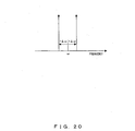
- Fig. 20 to Fig. 22 show the problemwhen a frequency amplitude deviation exists and the envelope amplitude of the original signal is small.
- Fig. 20 shows two unmodulated signals (continuous wave signals: CW signals) used to explain this problem.
- the two CW signals shown in Fig. 20 can be indicated by following expression. cos ⁇ ⁇ ⁇ ⁇ ⁇ ⁇ t ⁇ cos ⁇ ⁇ ⁇ t
- the input signal to the amplifier slips out of place and is expressed by an ellipse.
- the value of the envelope amplitude is expressed by the distance from the origin, so the original signal having the amplitude which should be shown in point A is shown in point B, and the value of the envelope amplitude becomes large.
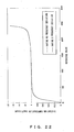
- Fig. 22 shows the distortion compensation coefficient which is made by the coefficient making unit 106 shown in Fig. 18 both when a frequency amplitude deviation exists and when no frequency amplitude deviation exists.
- an amplifier 100 has linear characteristics in the range in which the envelope amplitude as a reference value is small, and no distortion compensation should be required, thus making the value of distortion compensation coefficient 1.
- the reference value becomes larger, the output of the amplifier 100 becomes saturated, so the value of distortion compensation coefficient to compensate the saturation becomes larger than 1.
- the predistorter when a frequency amplitude deviation exists, the predistorter outputs a distortion compensation coefficient which is close to 0 at the position in which the value of the envelope amplitude is small or the reference value is small. This is a natural action as a predistorter.
- this distortion compensation coefficient is multiplied to the original signal, so the input signal to the amplifier 100 becomes smaller, and the output error of the amplifier 100 becomes larger.
- the signal which has passed through the amplifier namely the value of the waveform of time delay looks larger than the value of the original signal, so the value of distortion compensation coefficient to correct this phenomenon becomes smaller than a correct value.
- Fig. 25 shows the spike-shaped error of the distortion compensation coefficient which emerges at the position in which the emergence frequency is small. Because the emergence frequency is small at the position in which the absolute value of time differential is large, as described in Fig. 24 , it is considered that it takes time to converge the distortion compensation coefficient at such a position and that errors accumulate and spread. In such a case, a spike-shaped singular point of the distortion compensation coefficient emerges at only one position as shown in Fig. 25 , and a problem takes place in that no correct distortion compensation effect can be obtained.
- the purpose of the present invention is to achieve the distortion compensation of a power amplifier using the correct value of a distortion compensation coefficient when a frequency amplitude deviation exists or the emergence frequency is small.
- the purpose of the present invention is to compensate the distortion of an amplifier using the value of a correct distortion compensation coefficient when the value of envelope amplitude of an original signal is small, or at the position in which the time differential of the envelope value or the absolute value of time derivative is large.
- EP 1 204 216 A1 indicates that distortion compensation coefficients for correcting distortion of a transmission power amplifier are stored in a memory beforehand, a distortion compensation coefficient conforming to powers or amplitudes of a present transmit signal and a past transmit signal is read out of the memory, and distortion compensation processing is applied to the transmit signal using this distortion compensation coefficient.
- the transmit signal thus subjected to distortion compensation processing is then amplified by the transmission power amplifier and the amplified signal is transmitted, and the distortion compensation coefficient is updated based upon the transmit signal before distortion compensation and an output signal from the transmission power amplifier.
- Fig. 1 is a block diagram showing the configuration of the principle of the predistorter of the present invention.
- Fig. 1 is a block diagram showing the configuration of the principle of a predistorter 1 which performs operation using a distortion compensation coefficient for the input signal to a power amplifier which outputs a transmission power signal, and inputs the signal after the operation is performed to the power amplifier, and the predistorter comprises a distortion compensation coefficient storage unit 2 and a reference value conversion unit 3.
- a characteristic quantity of the envelope of a transmission signal before being inputted to the power amplifier for example, the amplitude value of the envelope, the time differential of the value of the envelope or the value of time derivative is used as the table reference value
- the distortion compensation coefficient storage unit 2 stores the distortion compensation coefficient corresponding to the reference value.
- the reference value conversion unit 3 converts a characteristic quantity into a predetermined value according to the size of the characteristic quantity, and outputs the converted value as a new table reference value. In this conversion, rounding upwards to a predetermined value and rounding downwards to an absolute value are used.
- the reference value conversion unit 3 can also round up the amplitude value to a predetermined value.
- the reference value conversion unit 3 when an unmodulated signal is included in a transmission signal, can round up the amplitude value to a value larger than the predetermined value. When a plurality of unmodulated signals are included in the transmission signal, the reference value conversion unit 3 can also change a value larger than the above-mentioned value to round up the amplitude value according to the number of unmodulated signals.
- the predistorter further comprises an operation unit which gives the result obtained by performing a predetermined operation for a characteristic value of the envelope according to the mean power of the transmission signal or the result obtained by not performing said predetermined operation according to the mean power of the transmission signal, as the characteristic quantity to the reference value conversion unit 3.
- the operation unit converts the amplitude value into power
- the operation unit converts the amplitude value into a dB value and gives the dB value to the reference value conversion unit 3, and when the given value is small, the reference value conversion unit 3 can round up the value to a predetermined value.
- the reference value conversion unit 3 when the characteristic quantity is both the amplitude value of the envelope and the time differential of the envelope or the value of time derivative, and the amplitude value is small, the reference value conversion unit 3 can round up that value to a predetermined value, and when the time differential or the absolute value of time derivative is large, the reference value conversion unit 3 can also round down that value to a predetermined absolute value or can convert that value into the value of the same code having a rounded-down absolute value.
- the predistorter further comprises an operation unit which outputs the result obtained by performing a certain operation for the value of envelope amplitude of a transmission signal according to the mean power of the transmission signal or the result obtained by not performing said operation, and the characteristic quantity is both the output result of the operation unit and the time differential of the envelope value or the value of time derivative, and when the output value of the operation unit is small, the reference value conversion unit 3 can round up that value to a predetermined value, and/or when the time differential or the absolute value of time derivative is large, the reference value conversion unit 3 can also round down that value to a predetermined absolute value.
- the operation unit converts the amplitude value of the envelope into power, and when the mean power of the transmission signal is small, the operation unit can convert the amplitude value of the envelope to a dB value.
- the predistorter further comprises an operation unit which obtains a first characteristic quantity as the result obtained by performing a predetermined operation for the amplitude value of the envelope according to the mean power of the transmission signal or the result obtained by not performing said operation, and the time differential of the first characteristic quantity or a second characteristic quantity as the value of time derivative, and when the value of the first characteristic quantity is small, the reference value conversion unit 3 can round up that value to a predetermined value, and when the absolute value of the second characteristic quantity is large, the reference value conversion unit 3 can also round down that value to a predetermined absolute value.
- the operation unit when the mean power of the transmission signal is large, the operation unit can convert the amplitude value of the envelope into power and when the mean power of the transmission signal is small, the operation unit can convert the amplitude value of the envelope into a dB value.
- the predistorter further comprises an operation unit which obtains a first characteristic quantity as the result obtained by performing a first predetermined operation for the amplitude value of the envelope according to the mean power of the transmission signal or the result obtained by not performing said operation, and a second characteristic quantity as the result obtained by performing a second predetermined operation for the time differential of the envelope or the value of time derivative, or the result obtained by not performing said operation, and when the first characteristic quantity is small, the reference value conversion unit 3 rounds up the quantity to a predetermined value, and/or when the absolute value of second characteristic quantity is large, the reference value conversion unit 3 can also round down that value to a predetermined value.
- the operation unit when the mean power of the transmission signal is large, the operation unit can convert the transmission signal into power as the first operation or/and the second operation, and when the mean power of the transmission signal is small, the operation unit can convert the transmission signal into a dB value as the first operation or/and the second operation.
- the value when the amplitude value of the envelope, for example, of a transmission signal is small, the value is rounded up to a predetermined value, and when the time differential of the value of the envelope or the absolute value of time derivative is large, the absolute value of that value is rounded down to a predetermined value, and is used as a reference value of the distortion compensation coefficient table.
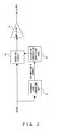
- Fig. 2 is a basic explanatory drawing of the predistortion method of the present invention.
- the operation for which a distortion compensation coefficient in the distortion compensation coefficient table 10 is used according to the characteristic quantity of the input is performed for the input of an amplifier by the operation circuit 11, and the output of the operation circuit 11 is given to the amplifier 12 and it becomes a transmission output signal.
- the characteristic quantity of the input as it is is not used, but the conversion in which, for example, the address as a reference level is rounded up or rounded down by the reference level conversion unit 13 is conducted, and as the result of the conversion, reference is made to the distortion compensation coefficient table 10 by the designated address.
- the input signal and part of the transmission output signal, i.e. part of the output of the directional coupler 18 are compared by the comparison computing unit 22, and errors are calculated, and the storage contents of the distortion compensation coefficient table 15 are updated by the coefficient making unit 23, for example, by using the LMS algorithm.
- the amplitude of the envelope of the input signal is calculated by the envelope amplitude calculation unit 20 in the same way as in Fig. 18 , but the calculation result of the amplitude as it is is not used as the address for referring to the distortion compensation coefficient table 15; the calculated amplitude value is rounded up by the set-value comparison/rounding-up unit 21 to a predetermined value, for example, a value having no influence of a frequency amplitude deviation close to an input value within a linear range of the amplifier, for example, the reference value of about 100 shown in Fig. 22 ; the rounded-up value is used as the address for referring to the distortion compensation coefficient table 15; and the distortion compensation coefficient stored in that address is given to the multiplication circuit 16.
- a method for determining the rounding-up set value of the reference value in addition to the method for setting a reference value to the input value having no influence of the frequency amplitude deviation, a method is also considered in which the input and output characteristics of the amplifier are examined and the reference value is set to the upper-limit value within a linear range, or the reference value is set to the input value which is lowered by 20 dB from the saturation level of the amplifier.
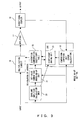
- Fig. 4 shows the operation when there is an unmodulated signal in an input signal in a first embodiment.
- an unmodulated signal a continuous wave (CW) signal
- the envelope amplitude value of the unmodulated signal takes a specific value
- the rounded-up level is all the more increased, that is to say, for example, the envelope amplitude value of the CW signal as it is needs to be added.
- a rounded-up set value given to the set-value comparison/rounding-up unit 21 is changed over by the rounding-up set-value changing-over unit 24.
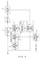
- Fig. 5 shows the operation of changing over the set value for rounding upwards according to the number of inputs of unmodulated signals in the first embodiment.
- the beat signal of the unmodulated signal for example, the amplitude of an offset sine wave in the case of two waves is obtained, and the rounded-up value must be raised by that value.
- the rounding-up set value is changed over by the rounding-up set-value changing-over unit 24 according to the result of the detection of the number of inputs of unmodulated signals, and is given to the set-value comparison/rounding-up unit 21.
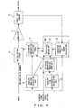
- Fig. 6 shows a predistortion method.
- the comparison rounding-up unit 26 is provided between the envelope time-differential calculation unit 25 and the distortion compensation coefficient table 15.
- the absolute value of the envelope time differential is compared with the set value set in advance.
- the distortion compensation coefficient whose the range of an absolute value is smaller is used, so the absolute value of the envelope time differential is rounded down, and the rounded-down value is used as the reference value of the distortion compensation coefficient table 15.
- Fig. 7 shows another predistortion method.
- the operation in the first embodiment and the operation in the second embodiment are performed alternatively or simultaneously.
- the comparison rounding-up unit 21 is provided between the envelope amplitude calculation unit 20 and the distortion compensation coefficient table 15, and the set-value comparison rounding-down unit 26 is provided between the envelope time-differential calculation unit 25 and the distortion compensation coefficient table 15.
- the reference value namely the reference address of the distortion compensation coefficient table 15
- the reference value is rounded up to the set rounded-up value.
- the absolute value of the time differential calculated by the envelope time-differential calculation unit 25 is larger than the set rounded-down absolute value, said absolute value of time differential is rounded down to the set rounded-down value by the set-value comparison rounding-down unit 26.
- the result obtained thereby is given as the reference address to the distortion compensation coefficient table 15.
- the reference value has a small absolute value which is set in advance, and reference is made to the table using the original time differential and the value of the same code as the reference address.
- Fig. 9 shows the predistortion method in a first embodiment.
- the operation circuit 30 is provided between the envelope amplitude calculation unit 20 and the set-value comparison/rounding-up unit 21, and operation is performed for the envelope amplitude value by the operation circuit 30 according to the value of mean power of the input signal, and the calculation result is given to the set-value comparison/rounding-up unit 21.
- the mean power of the input signal is obtained by a mean-value calculation integral circuit threshold comparison unit 31; saidmeanpower is compared with a preset threshold; change-over information is given to the operation circuit 30 according to the result obtained thereby; operation is performed by the operation circuit 30, and whether operation is performed for the calculation result of the amplitude value or whether the calculation result of the envelope amplitude calculation unit 20 is through given to the set-value comparison/rounding-up unit 21 is changed over.
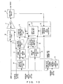
- Fig. 10 shows a first example of operation in a first embodiment.
- power calculation or the through unit 32 is used as a concrete example of the operation circuit 30 shown in Fig. 9 , and power conversion of the envelope amplitude value as the calculation result of the envelope amplitude calculation unit 20 is carried out, and the conversion result is given to the set-value comparison/rounding-up unit 21.
- the resolution of the part in which the envelope amplitude value is large can be improved, so when it is judged by the mean-value calculation integral circuit threshold comparison unit 31 that the mean power of the signal is larger than the threshold in which the mean power of the signal is large and in which power calculation is conducted by the power calculation or a trough unit 32, change-over information to conduct the power calculation is given to the power calculation or the through unit 32.
- Fig. 11 shows a second example of operation in a first embodiment.
- a dB calculation or the through unit 33 is provided between the envelope amplitude calculation unit 20 and the set-value comparison/rounding-up unit 21.
- the resolution in the part in which the envelope amplitude value is small can be improved, so when the mean power of the signal is small, the envelope amplitude value is converted to a dB value by the dB calculation or the through unit 33, and the conversion result is given to the set-value comparison/rounding-up unit 21.
- Fig. 12 shows the predistortion method in a second embodiment.
- rounding up the envelope amplitude value and rounding down the absolute value of envelope time differential are conducted as occasion demands, and reference is made to the distortion compensation coefficient table 15.
- the operation circuit 30 is provided between the envelope amplitude calculation unit 20 and the set-value comparison/rounding-up unit 21, but what differs from Fig. 9 is that the output of the operation circuit 30 is given to the envelope time-differential calculation unit 25, and the envelope time-differential calculation unit 25 calculates the absolute value of the envelope time differential using the output of the operation circuit 30, and the calculation result is given to the set-value comparison/rounding-down unit 26.
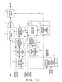
- Fig. 13 shows a first example of operation in a second embodiment.
- the power calculation or the through unit 32 is used as the operation circuit 30 of Fig. 12
- the envelope time-differential calculation unit 25 calculates the absolute value of the time differential of the envelope using the result obtained by having the value corresponding to the power obtained, for example, by squaring the amplitude value which is calculated by the envelope amplitude calculation unit 20, by the power calculation or the through unit 32.
- the mean value calculation integral circuit threshold comparison unit 31 outputs the change-over information which makes power calculation conducted to the power calculation or the through unit 32.
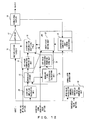
- Fig. 14 shows a second example of operation in a second embodiment.
- the dB calculation or the through unit 33 is provided in place of the operation circuit 30 shown in Fig. 12 .
- What differs from Fig. 11 is that, for example, when the mean power of the signal is small, the amplitude value calculated by the envelope amplitude calculation unit 20 is converted into a dB value, and the dB value is given to the set-value comparison/rounding-up unit 21, and at the same time, is given to the envelope time-differential calculation unit 25 as well.
- Fig. 15 shows the predistortion method in a third embodiment.
- the address for referring to the distortion compensation coefficient table 15 is rounded-up or rounded-down as occasion demands according to the calculation result of the envelope amplitude value and the absolute value of envelope time differential.
- the input signal is given to the envelope time-differential calculation unit 25 in the same way as in the first embodiment; an operation circuit of an absolute value part or the through unit 35 is provided between the envelope time-differential calculation unit 25 and the set-value comparison/rounding-down unit 26; operation is performed for the absolute value of time differential calculated by the envelope time-differential calculation unit 25, basically, independent of the operation circuit 30; and the calculation result is given to the set-value comparison/rounding-down unit 26.
- Change-over information is given to the operation of the absolute value part or the through unit 35 from the mean-value calculation integral circuit threshold comparison unit 31, and whether operation is performed or whether the calculation result of the envelope time-differential calculation unit 25 is given through to the set-value comparison/rounding-down unit 26 is controlled.
- Whether the operation circuit 30 performs operation and outputs the calculation result, or whether the calculation result of the envelope amplitude calculation unit 20 as it is is given through to the set-value comparison/rounding-up unit 21 is controlled by the change-over information which is outputted from the mean-value calculation integral circuit threshold comparison unit 31 as described above, but whether or not the operation circuit 30 performs the through operation or whether or not the operation circuit of the absolute value part or the through unit 35 performs the through operation is basically independent.
- Fig. 16 shows a first example of operation in a third embodiment.
- the power calculation of the absolute value part or the through unit 36 is provided as the operation circuit of the absolute value part or the through unit 35 shown in Fig. 15
- the operation circuit 30 the power calculation or the through unit 32 is provided in the same way, for example, as in Fig. 13 .
- the power calculation or through operation for the calculation result of the envelope amplitude calculation unit 20 and the power calculation or through operation for the absolute value of time differential as the calculation result of the envelope time-differential calculation unit 25 are controlled in accordance with the change-over information from the mean-value calculation integral circuit threshold comparison unit 31.
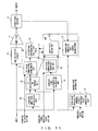
- Fig. 17 shows a second example of operation in a third embodiment.
- the power calculation or through operation by the power calculation of the absolute value part or the through unit 36 is conducted in the same way as in Fig. 16 , but what differs from Fig. 16 is that the conversion of the envelope amplitude value into a dB value or through operation is conducted by the dB calculation or the through unit 33 in the operation circuit 30 in the same way, for example, as in Fig. 14 .
- Described in the above third embodiment are an example of using the operation circuit which conducts power calculation for both the operation circuit 30 for the amplitude shown in Fig. 15 and the operation circuit 35 for the absolute value of time differential, and an example of conducting the dB calculation for the amplitude value and the power calculation for the absolute value of time differential.
- the operation circuit which conducts dB calculation for both operation circuits or power calculation for the amplitude value, and dB calculation for the absolute value of time differential as occasion demands.
- the accuracy of distortion compensation of an amplifier can be improved, thus contributing very much to the improvement of the performance of an amplifier using a predistorter.
- the present invention has been developed to improve the distortion compensation performance of a power amplifier for power transmission and can be used in the radio communications industry such as a cellular phone and in the broadcasting industry such as digital broadcasting.
Landscapes
- Engineering & Computer Science (AREA)
- Physics & Mathematics (AREA)
- Nonlinear Science (AREA)
- Power Engineering (AREA)
- Computer Networks & Wireless Communication (AREA)
- Signal Processing (AREA)
- Amplifiers (AREA)
Claims (17)
- Dispositif (1) de prédistorsion du type faisant référence à une table destiné à effectuer une opération (11 ; 16), en utilisant un coefficient de compensation de distorsion, sur un signal d'entrée (INPUT) d'un amplificateur (12 ; 17) de puissance qui sort un signal de puissance d'émission et qui entre le signal sur lequel l'opération a été effectuée, comprenant :une unité (2 ; 10 ; 15) de mémorisation de coefficients de compensation de distorsion destinée à mémoriser des coefficients de compensation de distorsion correspondant à des valeurs de référence d'une grandeur caractéristique (20, 25) de l'enveloppe du signal d'entrée ; etune unité (21, 26) de conversion de valeur de référence destinée à convertir la grandeur caractéristique en une valeur prédéterminée en fonction de la taille de la grandeur caractéristique ;caractérisé en ce qu'il comprend en outre une unité (30 ; 32 ; 33 ; 35 ; 36 ; 31) d'opération destinée à donner, en tant que grandeur caractéristique à l'unité (21, 26) de conversion de valeur de référence, en fonction de la puissance moyenne du signal, le résultat obtenu en effectuant une opération prédéterminée sur la valeur caractéristique de l'enveloppe du signal d'entrée, ou bien le résultat obtenu en n'effectuant pas ladite opération prédéterminée.
- Dispositif de prédistorsion du type faisant référence à une table selon la revendication 1, dans lequel, lorsque la grandeur caractéristique est la valeur d'amplitude de l'enveloppe (20) du signal d'entrée et que la valeur d'amplitude est petite, l'unité (21) de conversion de valeur de référence arrondit la valeur d'amplitude à une valeur supérieure prédéterminée.
- Dispositif de prédistorsion du type faisant référence à une table selon la revendication 2, dans lequel, lorsqu'un signal non modulé (CW) est inclus dans le signal d'entrée, l'unité (21, 24) de conversion de valeur de référence arrondit la valeur d'amplitude à une valeur plus grande que la valeur prédéterminée.
- Dispositif de prédistorsion du type faisant référence à une table selon la revendication 3, dans lequel, lorsqu'une pluralité de signaux non modulés est incluse dans le signal d'entrée, l'unité (21, 24) de conversion de valeur de référence change une valeur plus grande pour arrondir la valeur de référence en fonction du nombre de signaux non modulés.
- Dispositif de prédistorsion du type faisant référence à une table selon la revendication 1,
dans lequel, lorsque la valeur caractéristique est la valeur d'amplitude de l'enveloppe (20) du signal d'entrée, et que la puissance moyenne du signal d'entrée est grande, l'unité (32) d'opération convertit la valeur d'amplitude en puissance et donne la puissance convertie à l'unité (21) de conversion de valeur de référence, et
dans lequel, lorsque la grandeur caractéristique après que l'amplitude a été convertie en puissance est petite, l'unité (21) de conversion de valeur de référence arrondit la grandeur caractéristique à une valeur supérieure prédéterminée. - Dispositif de prédistorsion du type faisant référence à une table selon la revendication 1,
dans lequel, lorsque la valeur caractéristique est la valeur d'amplitude de l'enveloppe (20) du signal d'entrée, et que la puissance moyenne du signal d'entrée est petite, l'unité (33) d'opération convertit la valeur d'amplitude en une valeur en dB et la donne, en tant que grandeur caractéristique, à l'unité (21) de conversion de valeur de référence, et
dans lequel, lorsque la grandeur caractéristique est petite, l'unité (21) de conversion de référence arrondit la grandeur caractéristique à une valeur supérieure prédéterminée. - Dispositif de prédistorsion du type faisant référence à une table selon la revendication 1, dans lequel, lorsque la grandeur caractéristique est à la fois la valeur d'amplitude de l'enveloppe (20) du signal d'entrée et la différentielle par rapport au temps de la valeur de l'enveloppe (25) ou la valeur de la dérivée par rapport au temps, et que la valeur d'amplitude est petite, l'unité (21) de conversion de valeur de référence arrondit cette valeur à une valeur supérieure prédéterminée.
- Dispositif de prédistorsion du type faisant référence à une table selon la revendication 1,
dans lequel, lorsque la grandeur caractéristique est à la fois la valeur d'amplitude de l'enveloppe (20) du signal d'entrée et la différentielle par rapport au temps de la valeur de l'enveloppe (25) ou la valeur de la dérivée par rapport au temps, et que la valeur d'amplitude est petite, l'unité (21, 26) de conversion de valeur de référence arrondit cette valeur à une valeur supérieure prédéterminée ; et/ou
dans lequel, lorsque la différentielle par rapport au temps ou la valeur absolue de la dérivée par rapport au temps est grande, l'unité (21, 26) de conversion de valeur de référence arrondit cette valeur à une valeur inférieure prédéterminée et convertit cette valeur en la valeur du même code que la différentielle par rapport au temps ou la dérivée par rapport au temps. - Dispositif de prédistorsion du type faisant référence à une table selon la revendication 1, dans lequel l'unité (30 ; 32 ; 33 ; 35 ; 36 ; 31) d'opération sort le résultat obtenu en effectuant une opération prédéterminée pour la valeur d'amplitude de l'enveloppe du signal d'entrée en fonction de la puissance moyenne du signal d'émission ou du résultat obtenu en n'effectuant pas ladite opération, et
dans lequel la grandeur caractéristique est à la fois la sortie de l'unité d'opération et la différentielle par rapport au temps de la valeur de l'enveloppe (25) du signal d'entrée ou la valeur de la dérivée par rapport au temps ;
dans lequel, lorsque la sortie de l'unité d'opération est petite, l'unité (21, 26) de conversion de valeur de référence arrondit cette valeur de sortie à une valeur supérieure prédéterminée ; et/ou
dans lequel, lorsque la différentielle par rapport au temps ou la valeur absolue de la dérivée par rapport au temps est grande, l'unité (21, 26) de conversion de valeur de référence arrondit cette valeur à une valeur inférieure prédéterminée et convertit cette valeur en une valeur du même code que la différentielle par rapport au temps ou la dérivée par rapport au temps. - Dispositif de prédistorsion du type faisant référence à une table selon la revendication 9, dans lequel, lorsque la puissance moyenne du signal d'entrée est grande, l'unité (32) d'opération effectue l'opération pour convertir en puissance la valeur d'amplitude de l'enveloppe.
- Dispositif de prédistorsion du type faisant référence à une table selon la revendication 9, dans lequel, lorsque la puissance moyenne du signal d'entrée est petite, l'unité (33) d'opération effectue l'opération pour convertir en une valeur en dB la valeur d'amplitude de l'enveloppe.
- Dispositif de prédistorsion du type faisant référence à une table selon la revendication 1, dans lequel l'unité (30 ; 32 ; 33 ; 35 ; 36 ; 31 ; 25) d'opération obtient une première grandeur caractéristique comme le résultat obtenu en effectuant une opération prédéterminée pour la valeur d'amplitude de l'enveloppe en fonction de la puissance moyenne du signal d'entrée ou bien le résultat obtenu en n'effectuant pas ladite opération, et une seconde grandeur caractéristique comme différentielle par rapport au temps de la première grandeur caractéristique ou comme valeur de dérivée par rapport au temps,
dans lequel, lorsque la première grandeur caractéristique est petite, l'unité (21, 26) de conversion de valeur de référence arrondit la première grandeur caractéristique à une valeur supérieure prédéterminée ; et/ou
dans lequel, lorsque la valeur absolue de la seconde grandeur caractéristique est grande, l'unité (21, 26) de conversion de valeur de référence arrondit cette valeur à une valeur inférieure prédéterminée et convertit cette valeur en une valeur du même code que la seconde grandeur caractéristique. - Dispositif de prédistorsion du type faisant référence à une table selon la revendication 12, dans lequel, lorsque la puissance moyenne du signal d'entrée est grande, l'unité (32) d'opération effectue l'opération pour convertir en puissance la valeur d'amplitude de l'enveloppe.
- Dispositif de prédistorsion du type faisant référence à une table selon la revendication 12, dans lequel, lorsque la puissance moyenne du signal d'entrée est petite, l'unité (33) d'opération effectue l'opération pour convertir en une valeur en dB la valeur d'amplitude de l'enveloppe.
- Dispositif de prédistorsion du type faisant référence à une table selon la revendication 1, dans lequel l'unité (30 ; 32 ; 33 ; 35 ; 36 ; 31 ; 25) d'opération obtient une première grandeur caractéristique comme le résultat obtenu en effectuant ladite opération prédéterminée pour la valeur d'amplitude de l'enveloppe du signal d'entrée en fonction de la puissance moyenne du signal d'entrée ou bien le résultat obtenu en n'effectuant pas ladite opération, et une seconde grandeur caractéristique comme le résultat obtenu en effectuant une seconde opération prédéterminée pour la différentielle par rapport au temps de la valeur d'enveloppe ou la valeur absolue de la dérivée par rapport au temps, ou bien le résultat obtenu en n'effectuant pas ladite opération,
dans lequel, lorsque la première grandeur caractéristique est petite, l'unité (21, 26) de conversion de valeur de référence arrondit la première grandeur caractéristique à une valeur supérieure prédéterminée ; et/ou
dans lequel, lorsque la valeur absolue de la seconde grandeur caractéristique est grande, l'unité (21, 26) de conversion de valeur de référence arrondit la valeur absolue à une valeur inférieure prédéterminée et convertit cette valeur en une valeur du même code que la seconde grandeur caractéristique. - Dispositif de prédistorsion du type faisant référence à une table selon la revendication 15, dans lequel, lorsque la puissance moyenne du signal d'entrée est grande, la première opération et/ou la seconde opération est une opération de conversion en puissance.
- Dispositif de prédistorsion du type faisant référence à une table selon la revendication 15, dans lequel, lorsque la puissance moyenne du signal d'entrée est petite, la première opération et/ou la seconde opération est une opération de conversion en une valeur en dB.
Applications Claiming Priority (1)
| Application Number | Priority Date | Filing Date | Title |
|---|---|---|---|
| PCT/JP2002/005373 WO2003103167A1 (fr) | 2002-05-31 | 2002-05-31 | Appareil de predistorsion a reference de tableau |
Publications (3)
| Publication Number | Publication Date |
|---|---|
| EP1511182A1 EP1511182A1 (fr) | 2005-03-02 |
| EP1511182A4 EP1511182A4 (fr) | 2007-05-02 |
| EP1511182B1 true EP1511182B1 (fr) | 2011-07-13 |
Family
ID=29606645
Family Applications (1)
| Application Number | Title | Priority Date | Filing Date |
|---|---|---|---|
| EP02730844A Expired - Lifetime EP1511182B1 (fr) | 2002-05-31 | 2002-05-31 | Appareil de predistorsion a reference de tableau |
Country Status (4)
| Country | Link |
|---|---|
| US (1) | US7392020B2 (fr) |
| EP (1) | EP1511182B1 (fr) |
| JP (1) | JP4077449B2 (fr) |
| WO (1) | WO2003103167A1 (fr) |
Families Citing this family (27)
| Publication number | Priority date | Publication date | Assignee | Title |
|---|---|---|---|---|
| US8472897B1 (en) | 2006-12-22 | 2013-06-25 | Dali Systems Co. Ltd. | Power amplifier predistortion methods and apparatus |
| US8380143B2 (en) | 2002-05-01 | 2013-02-19 | Dali Systems Co. Ltd | Power amplifier time-delay invariant predistortion methods and apparatus |
| US6985704B2 (en) * | 2002-05-01 | 2006-01-10 | Dali Yang | System and method for digital memorized predistortion for wireless communication |
| US8811917B2 (en) | 2002-05-01 | 2014-08-19 | Dali Systems Co. Ltd. | Digital hybrid mode power amplifier system |
| US7403153B2 (en) * | 2004-12-15 | 2008-07-22 | Valeo Raytheon Systems, Inc. | System and method for reducing a radar interference signal |
| US7683827B2 (en) | 2004-12-15 | 2010-03-23 | Valeo Radar Systems, Inc. | System and method for reducing the effect of a radar interference signal |
| CN101189792B (zh) * | 2005-03-09 | 2010-07-14 | 富士通株式会社 | 失真补偿装置 |
| DE102005013880B3 (de) * | 2005-03-24 | 2006-04-20 | Infineon Technologies Ag | Verfahren zur Vorverzerrung eines Signals und Sendeeinrichtung mit digitaler Vorverzerrung, insbesondere für Mobilfunk |
| JP4323470B2 (ja) * | 2005-08-08 | 2009-09-02 | 富士通株式会社 | アドレス生成装置およびその方法 |
| CN101479956B (zh) | 2006-04-28 | 2013-07-31 | 大力系统有限公司 | 用于无线通信的高效率线性化功率放大器 |
| KR20100014339A (ko) | 2006-12-26 | 2010-02-10 | 달리 시스템즈 씨오. 엘티디. | 다중 채널 광대역 통신 시스템에서의 기저 대역 전치 왜곡 선형화를 위한 방법 및 시스템 |
| US9026067B2 (en) | 2007-04-23 | 2015-05-05 | Dali Systems Co. Ltd. | Remotely reconfigurable power amplifier system and method |
| US7688135B2 (en) * | 2007-04-23 | 2010-03-30 | Dali Systems Co. Ltd. | N-way Doherty distributed power amplifier |
| US8274332B2 (en) * | 2007-04-23 | 2012-09-25 | Dali Systems Co. Ltd. | N-way Doherty distributed power amplifier with power tracking |
| US8224266B2 (en) * | 2007-08-30 | 2012-07-17 | Dali Systems Co., Ltd. | Power amplifier predistortion methods and apparatus using envelope and phase detector |
| CN102150361B (zh) * | 2007-12-07 | 2016-11-09 | 大力系统有限公司 | 基带导出的射频数字预失真 |
| US8391808B2 (en) * | 2008-02-28 | 2013-03-05 | Broadcom Corporation | Method and system for estimating and compensating non-linear distortion in a transmitter using calibration |
| JP5176692B2 (ja) * | 2008-05-28 | 2013-04-03 | 日本電気株式会社 | 歪補償回路及び歪補償方法 |
| US8542768B2 (en) | 2009-12-21 | 2013-09-24 | Dali Systems Co. Ltd. | High efficiency, remotely reconfigurable remote radio head unit system and method for wireless communications |
| CN106160674A (zh) | 2009-12-21 | 2016-11-23 | 大力系统有限公司 | 用于改善发射机与接收机之间的隔离的系统 |
| US8730786B2 (en) | 2009-12-21 | 2014-05-20 | Dali Systems Co. Ltd. | Remote radio head unit system with wideband power amplifier and method |
| US8351877B2 (en) | 2010-12-21 | 2013-01-08 | Dali Systems Co. Ltfd. | Multi-band wideband power amplifier digital predistorition system and method |
| JP2010179152A (ja) * | 2010-05-10 | 2010-08-19 | Mks Instruments Inc | 増幅器を安定化する方法およびシステム |
| KR101829517B1 (ko) | 2010-09-14 | 2018-02-14 | 달리 시스템즈 씨오. 엘티디. | 원격으로 재구성가능한 분산 안테나 시스템 및 방법 |
| CN102480450B (zh) * | 2010-11-30 | 2014-12-10 | 富士通株式会社 | 预失真器控制装置和方法、功率控制状态检测方法 |
| CN104301268B (zh) * | 2013-07-19 | 2019-05-21 | 中兴通讯股份有限公司 | 多通道预失真方法及装置 |
| JP6413795B2 (ja) | 2015-01-23 | 2018-10-31 | 富士通株式会社 | 歪補償装置 |
Family Cites Families (13)
| Publication number | Priority date | Publication date | Assignee | Title |
|---|---|---|---|---|
| JP2746130B2 (ja) * | 1994-07-25 | 1998-04-28 | 日本電気株式会社 | 非線形特性発生回路 |
| JPH09199959A (ja) * | 1996-01-11 | 1997-07-31 | Hitachi Denshi Ltd | 無線機 |
| JPH10322137A (ja) * | 1997-05-20 | 1998-12-04 | Matsushita Electric Ind Co Ltd | プリディストーション型歪補償回路付送信装置 |
| JP3772031B2 (ja) | 1998-09-02 | 2006-05-10 | 富士通株式会社 | 増幅器のプリディストータと増幅装置 |
| JP4086133B2 (ja) | 1999-07-28 | 2008-05-14 | 富士通株式会社 | 無線装置の歪補償方法及び歪補償装置 |
| JP4256057B2 (ja) * | 1999-09-30 | 2009-04-22 | 株式会社東芝 | 非線形補償器 |
| JP4183364B2 (ja) | 1999-12-28 | 2008-11-19 | 富士通株式会社 | 歪補償装置 |
| JP2001313532A (ja) | 2000-05-01 | 2001-11-09 | Sony Corp | 歪み補償装置 |
| JP2001352219A (ja) | 2000-06-08 | 2001-12-21 | Sony Corp | 非線形歪補償装置 |
| JP2002064411A (ja) | 2000-08-16 | 2002-02-28 | Matsushita Electric Ind Co Ltd | ディジタル送信装置 |
| JP2002094335A (ja) * | 2000-09-19 | 2002-03-29 | Japan Science & Technology Corp | 非線形歪み補償電力増幅器 |
| JP2002135062A (ja) * | 2000-10-23 | 2002-05-10 | Sony Corp | 歪み補償電力増幅装置 |
| JP3994308B2 (ja) * | 2000-10-26 | 2007-10-17 | 株式会社ケンウッド | プリディストーション型歪補償回路 |
-
2002
- 2002-05-31 WO PCT/JP2002/005373 patent/WO2003103167A1/fr active Application Filing
- 2002-05-31 JP JP2004510130A patent/JP4077449B2/ja not_active Expired - Fee Related
- 2002-05-31 EP EP02730844A patent/EP1511182B1/fr not_active Expired - Lifetime
-
2004
- 2004-11-30 US US10/999,495 patent/US7392020B2/en not_active Expired - Fee Related
Also Published As
| Publication number | Publication date |
|---|---|
| WO2003103167A1 (fr) | 2003-12-11 |
| JP4077449B2 (ja) | 2008-04-16 |
| EP1511182A4 (fr) | 2007-05-02 |
| EP1511182A1 (fr) | 2005-03-02 |
| US7392020B2 (en) | 2008-06-24 |
| JPWO2003103167A1 (ja) | 2005-10-06 |
| US20050079834A1 (en) | 2005-04-14 |
Similar Documents
| Publication | Publication Date | Title |
|---|---|---|
| EP1511182B1 (fr) | Appareil de predistorsion a reference de tableau | |
| US6418173B1 (en) | Transmission Apparatus | |
| EP1797639B1 (fr) | Generation de tables de distorsion prealable de formes d'onde arbitraires | |
| EP1858158B1 (fr) | Dispositif de compensation de deformation | |
| US6577192B2 (en) | Predistortion-type distortion compensation amplifying apparatus | |
| EP1705801B1 (fr) | Appareil de compensation de distorsion | |
| JP4284630B2 (ja) | 歪補償増幅装置 | |
| EP1085668B1 (fr) | Un procédé et appareil pour reduire la puissance de canaux voisins dans des systèmes de communication sans-fil | |
| EP2521261A1 (fr) | Système et procédé de distorsion préalable à injection numérique ameliorée à bande large | |
| EP2202879A1 (fr) | Appareil de prédistorsion et procédé de prédistorsion | |
| EP1322034B1 (fr) | Circuit préaccentuation | |
| CN101908861A (zh) | 传送器、输出信号失真降低方法及预失真参数产生方法 | |
| EP1193865B1 (fr) | Dispositif et méthode pour la compensation de la distortion | |
| US6396344B1 (en) | Amplifier linearization by learned linear behavior | |
| EP2525488A1 (fr) | Dispositif amplificateur et dispositif de traitement du signal | |
| EP1450482B1 (fr) | Circuit et procédé pour la compensation des distorsions non-linéaires d'un amplificateur de puissance | |
| US9337783B2 (en) | Distortion compensation apparatus and distortion compensation method | |
| US20030231058A1 (en) | Transmission amplifier | |
| US5862457A (en) | Multichannel predistortion linearizer | |
| KR20110103329A (ko) | 무선 장치, 왜곡 보상 장치 및 왜곡 보상 방법 | |
| KR100939882B1 (ko) | 왜곡 보상 장치 | |
| KR100625445B1 (ko) | 가변차수 전치왜곡장치 및 그의 제어 방법 | |
| JP2000244370A (ja) | 無線通信装置の送信部の非線形歪補償方法および無線通信装置 | |
| CN115102509A (zh) | 数字预失真方法和数字预失真系统 | |
| WO2008035439A1 (fr) | Circuit de compensation de distorsion et procÉDÉ pour commander celui-ci |
Legal Events
| Date | Code | Title | Description |
|---|---|---|---|
| PUAI | Public reference made under article 153(3) epc to a published international application that has entered the european phase |
Free format text: ORIGINAL CODE: 0009012 |
|
| 17P | Request for examination filed |
Effective date: 20041222 |
|
| AK | Designated contracting states |
Kind code of ref document: A1 Designated state(s): DE FR GB IT |
|
| A4 | Supplementary search report drawn up and despatched |
Effective date: 20070329 |
|
| 17Q | First examination report despatched |
Effective date: 20100701 |
|
| GRAP | Despatch of communication of intention to grant a patent |
Free format text: ORIGINAL CODE: EPIDOSNIGR1 |
|
| RIN1 | Information on inventor provided before grant (corrected) |
Inventor name: ISHIKAWA, HIROYOSHIFUJITSU LIMITED Inventor name: KUBO, TOKUROFUJITSU LIMITED Inventor name: NAGATANI, KAZUOFUJITSU LIMITED Inventor name: MANIWA, TORUFUJITSU LIMITED |
|
| GRAS | Grant fee paid |
Free format text: ORIGINAL CODE: EPIDOSNIGR3 |
|
| GRAA | (expected) grant |
Free format text: ORIGINAL CODE: 0009210 |
|
| AK | Designated contracting states |
Kind code of ref document: B1 Designated state(s): DE FR GB IT |
|
| REG | Reference to a national code |
Ref country code: GB Ref legal event code: FG4D |
|
| REG | Reference to a national code |
Ref country code: DE Ref legal event code: R096 Ref document number: 60240501 Country of ref document: DE Effective date: 20110901 |
|
| PLBE | No opposition filed within time limit |
Free format text: ORIGINAL CODE: 0009261 |
|
| STAA | Information on the status of an ep patent application or granted ep patent |
Free format text: STATUS: NO OPPOSITION FILED WITHIN TIME LIMIT |
|
| PG25 | Lapsed in a contracting state [announced via postgrant information from national office to epo] |
Ref country code: IT Free format text: LAPSE BECAUSE OF FAILURE TO SUBMIT A TRANSLATION OF THE DESCRIPTION OR TO PAY THE FEE WITHIN THE PRESCRIBED TIME-LIMIT Effective date: 20110713 |
|
| 26N | No opposition filed |
Effective date: 20120416 |
|
| REG | Reference to a national code |
Ref country code: DE Ref legal event code: R097 Ref document number: 60240501 Country of ref document: DE Effective date: 20120416 |
|
| REG | Reference to a national code |
Ref country code: FR Ref legal event code: PLFP Year of fee payment: 15 |
|
| REG | Reference to a national code |
Ref country code: FR Ref legal event code: PLFP Year of fee payment: 16 |
|
| PGFP | Annual fee paid to national office [announced via postgrant information from national office to epo] |
Ref country code: FR Payment date: 20170413 Year of fee payment: 16 Ref country code: DE Payment date: 20170523 Year of fee payment: 16 Ref country code: GB Payment date: 20170531 Year of fee payment: 16 |
|
| REG | Reference to a national code |
Ref country code: DE Ref legal event code: R119 Ref document number: 60240501 Country of ref document: DE |
|
| GBPC | Gb: european patent ceased through non-payment of renewal fee |
Effective date: 20180531 |
|
| PG25 | Lapsed in a contracting state [announced via postgrant information from national office to epo] |
Ref country code: DE Free format text: LAPSE BECAUSE OF NON-PAYMENT OF DUE FEES Effective date: 20181201 Ref country code: GB Free format text: LAPSE BECAUSE OF NON-PAYMENT OF DUE FEES Effective date: 20180531 Ref country code: FR Free format text: LAPSE BECAUSE OF NON-PAYMENT OF DUE FEES Effective date: 20180531 |