EP1511065B1 - Méthode pour la focalisation d'un appareil à faisceau de particules chargées à l'aide de l'astigmatisme du faisceau de particules chargées - Google Patents
Méthode pour la focalisation d'un appareil à faisceau de particules chargées à l'aide de l'astigmatisme du faisceau de particules chargées Download PDFInfo
- Publication number
- EP1511065B1 EP1511065B1 EP04077317A EP04077317A EP1511065B1 EP 1511065 B1 EP1511065 B1 EP 1511065B1 EP 04077317 A EP04077317 A EP 04077317A EP 04077317 A EP04077317 A EP 04077317A EP 1511065 B1 EP1511065 B1 EP 1511065B1
- Authority
- EP
- European Patent Office
- Prior art keywords
- image
- astigmatic
- objective lens
- setting
- region
- Prior art date
- Legal status (The legal status is an assumption and is not a legal conclusion. Google has not performed a legal analysis and makes no representation as to the accuracy of the status listed.)
- Expired - Fee Related
Links
Images

Classifications
-
- H—ELECTRICITY
- H01—ELECTRIC ELEMENTS
- H01J—ELECTRIC DISCHARGE TUBES OR DISCHARGE LAMPS
- H01J37/00—Discharge tubes with provision for introducing objects or material to be exposed to the discharge, e.g. for the purpose of examination or processing thereof
- H01J37/02—Details
- H01J37/21—Means for adjusting the focus
-
- H—ELECTRICITY
- H01—ELECTRIC ELEMENTS
- H01J—ELECTRIC DISCHARGE TUBES OR DISCHARGE LAMPS
- H01J2237/00—Discharge tubes exposing object to beam, e.g. for analysis treatment, etching, imaging
- H01J2237/21—Focus adjustment
- H01J2237/216—Automatic focusing methods
Definitions
- the invention pertains to a method for focusing a beam of electrically-charged particles in a particle-optical device with an imaging objective lens.
- the nominal refractive power of the objective lens is first determined; that is to say the refractive power value for which the electron beam is approximately focused on the specimen. A deviation from this nominal setting is then applied, such that a setting of "over-focus” arises; additionally a deviation from the nominal setting is applied such that a setting of "under-focus” arises.
- the two images which are made at the two different settings of the imaging objective lens therefore consist of an "over-focus” image and an "under-focus” image.
- the total spectral energy content of both images is determined, as is the difference between the spectral energy content of the "over-focus" image and the "under-focus” image.
- the ratio R of this difference to the total spectral energy content gives a measure of the defocusing of the electron beam. If R is positive, then the "over-focus” image is sharper than the "under-focus” image and the focal length must therefore be shortened; if R is negative, the "under-focus” image is sharper than the "over-focus” image and the focal length must therefore be lengthened.
- the spectral energy content of a number of sectors of the image is determined for each of the two images, and, on the basis of the difference between the respective spectral energy contents, a decision is made as regards in which direction the astigmatism must be increased or decreased in order to arrive at a beam which is virtually free of astigmatism.
- the beam that is to be focused is deliberately made astigmatic and the astigmatism in this beam is used for focusing the beam.
- Use is thereby made of the insight known per se that the direction of the smearing in the image as caused by the astigmatism changes by 90° in direction when the focus of the beam changes from over-focus to under-focus or vice versa.
- a first image of the specimen is made with a known direction of the astigmatism applied to the beam, and the smearing in this image as a result of that astigmatism is determined (steps a to c).
- a second image of the specimen is made at a different setting of the objective lens ⁇ likewise with a known direction of the astigmatism applied to this beam ⁇ and the smearing in this second image as a result of that astigmatism is determined (steps d to g). It is convenient if the direction of the astigmatism in the first image is equal to that in the second image, although this is not necessary. It is now assumed that the direction of the astigmatism in the beam in both instances is the same.
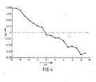
- An advantage of the method according to the invention lies in the fact that, with this method, a zero-crossing is sought (namely, in the interpolation between the first setting of the objective lens and the last-obtained setting of the objective lens, so as to determine that setting of the objective lens whereby the beam of electrically charged particles attains its optimum focus), which, in general, offers a faster convergence of the algorithm to be applied in the method than the usual methods for automatic focusing in a particle-optical device, where the algorithms employed seek a minimum or a maximum.
- the course of a curve in the neighborhood of an extremity is relatively flat, while that in the neighborhood of a zero-crossing is much less flat.
- the determination of the direction of the astigmatic smearing in an image takes place by determining the spectral energy content of a first spectral region of the image in question with a first direction, and of the spectral energy content of a second spectral region of that image with a second direction transverse to the first direction, and by determining at least the sign of the difference between the spectral energy content in the first region and the spectral energy content in the second region.
- a sector is chosen (a first spectral region of the image in question with a first direction) in a two-dimensional graphical depiction of the spectral energy content, and the energy content in said sector is determined; this is also done with a sector transverse (preferably perpendicular) thereto (a second spectral region of that image with a second direction transverse to the first direction).
- a sector transverse preferably perpendicular
- the one spectral energy content will differ from the other, and, from the sign of this difference, the direction of the smearing can be determined.
- the comparison of the direction of the astigmatic smearing in the image made in step (b) with that of the image made in step (f) takes place by comparing the signs of the difference in the spectral energy content of the first region and of the spectral energy content of the second region of each of the images.
- the process mentioned in the previous paragraph in applied to each of the two images so as to determine the direction of the astigmatic smearing. From the sign of the difference between these two directions, it can be ascertained if the astigmatic smearings have the same direction or are transverse to each other.
- This embodiment of the invention is of particular advantage for specimens with a structure having a strong degree of directional preference, as is the case for example with integrated circuits.
- two images are made with transversely disposed (preferably mutually perpendicular) astigmatism.
- the same is done at a second setting of the objective lens.
- two different sectors are again chosen in (the two-dimensional graphical depiction of) the spectral energy content (which sectors preferably have mutually-perpendicular oriented central axes) and the difference is determined between the spectral energy contents of each of those two sectors, which difference shall be referred to here as the sector-difference.
- This difference provides a measure of the magnitude and direction of the anisotropy which exists in the image in question. Both the directional preference of the specimen and the astigmatism in the beam have therefore contributed to this anisotropy.
- the aforementioned sector-difference is determined for each of the four images mentioned in this embodiment.
- the contribution of the structures in the specimen having a strong directional preference is the same in each of the sector-differences; when one therefore determines the difference between these two sector-differences (the final difference), then this contribution will be cancelled.
- the final difference reflects almost exclusively the effect of the astigmatic smearing. This is applicable both to the final difference of the images made at the first setting of the objective lens and to the final difference of the images made at the second setting of the objective lens.
- the two final differences thus formed can now be mutually compared, and, on the basis of this comparison, it can be determined if the image made at the first setting of the objective lens either does or does not exhibit a direction of the astigmatic smearing equal to that in the image made at the second setting of the objective lens.
- the previously-mentioned continuation of the method can be carried out ⁇ that is to say, in the case of equality of the directions of the astigmatic smearing, the repeating of steps (k) and (1), and, in the case of inequality of these directions, the performing of an interpolation process between the first setting of the objective lens and the last-obtained setting of the objective lens so as to determine that setting of the objective lens whereby the beam of electrically charged particles attains its optimum focus.
- the performance of the interpolation process between the first setting of the objective lens and the last-obtained setting of the objective lens takes place in that:
- a different value of the astigmatism is additionally set for the image made attendant to step (o).
- the form of the elliptical cross-section of the astigmatic beam (the "ellipticality") can be used to increase the sensitivity of the result of the algorithm. This sensitivity is preferably maximized for as small as possible an effort of the algorithm.
- the influence of the spectral content of the image can be increased by adapting the ratio of the long and the short axes (the "ellipticality") to the degree to which the algorithm has approximated the optimum focus.
- the image processing occurs in digital form and a subframe of the image in question is formed in order to determine the spectral energy content of the aforementioned spectral regions.
- a substantial reduction in the calculation burden of the algorithm is effected, whereby faster focusing of the beam can be achieved.
- the forming of a subframe can occur through the selection of a region in the image with the correct information-content and the performance of the further processing of the method according to the invention with this sub-region.
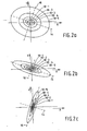
- Figure 1 schematically depicts an astigmatic electron beam 2.
- the direction of the electrons in this beam is from top to bottom.
- the nominal focus in this beam is situated at the location of the cross-section 4, which cross-section is circular at this location.
- Above and below the nominal focus the beam has an elliptical cross-section, as is depicted by the ellipses 6 and 8.
- the long (short) axis of ellipse 6 is thereby perpendicular to the corresponding axis of ellipse 8.
- a specimen in an electron microscope can now be illuminated with the depicted astigmatic beam and images can be made in a manner usual to such a microscope, with the understanding that for the application of the invention, the beam is deliberately made astigmatic at the outset and that the method according to the invention generally begins with illuminating the specimen with an astigmatic cross-section of the electron beam.
- the result of using such an illumination in the making of an image is that each image-point will be stretched in the direction of the long axis of the ellipse rather than being round (that is to say, point-shaped by approximation), and is therefore stripe-like by approximation, whereby a "smearing" in the image in the direction of the long axis will occur.
- the degree of smearing can be quantized by subjecting the image to a well-known method for the spectral analysis of the spatial frequencies occurring in the image, such as, for example, the so-called Fast Fourier Transform (FFT).
- FFT provides a representation of the distribution of the spectral energy (the energy spectrum) occurring in the image as a function of the spatial frequency; in the case of a two-dimensional image, that will therefore be as a function of the spatial frequencies in both the x and y directions.
- a graphical representation of the result of this FFT applied to an electron microscope image is depicted in Figures 2a, 2b and 2c .
- Figure 2a shows the graphical representation of an energy spectrum of a non-isotropic specimen imaged with a non-astigmatic beam
- Figure 2b shows the graphical representation of an energy spectrum of the specimen according to Figure 2a imaged with an astigmatic beam with a first direction of the astigmatism
- Figure 2c shows the graphical representation of an energy spectrum of the specimen according to Figure 2a imaged with an astigmatic beam with a direction of the astigmatism perpendicular to that of Figure 2b .
- the energy spectrum in Figure 2a is based on an image with a non-astigmatic beam.
- an energy spectrum with circular lines of equal relative energy 18-1 to 18-5 ⁇ in general 18-i ⁇ because such a beam cannot exhibit any smearing in an astigmatic direction.
- the fact that the depicted lines 18-i nevertheless are not circles is caused by anisotropy in the specimen, that is to say that the specimen itself exhibits spatial frequencies in one direction which differ from those in other directions.
- the specimen has more high spatial frequencies in the direction of the broken line 14 than in the direction of broken line 16; this can be caused, for example, by the fact that the specimen contains many oblong details whose longitudinal direction lies in the direction of the broken line 16.
- the energy spectrum is based on an image of the same specimen as in Fig. 2a but then illuminated with an astigmatic beam.
- the lines of equal relative energy 18-i hereby exhibit smearing in a direction which is determined by the combination of the anisotropy in the specimen and the astigmatism in the beam. If the depicted specimen had the same direction as in the image according to Fig. 2a then it can be assumed that the direction of the long axis of the elliptical cross-section of the beam with which the specimen was illuminated is the same as that of the longitudinal direction of the oblong details in the specimen.
- the energy spectrum is based on an image of the same specimen as in Figures 2a and 2b , but then illuminated with an astigmatic beam whose direction of astigmatism is perpendicular to that of Fig. 2b .
- the lines of equal relative energy 18-i hereby exhibit a smearing in a direction which, just as in Fig. 2b , is determined by the anisotropy in the specimen and the astigmatism in the beam. Because the high frequencies in Fig.
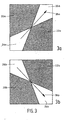
- Figure 3 is a depiction of two maskings that are to be applied to the energy-spectra of the images made with the astigmatic beams in order to determine the astigmatic smearing.
- the FFT of an image reflects the distribution of the spectral energy in the image as a function of the spatial frequency; in the case of a two-dimensional image this is therefore as a function of the spatial frequencies in both the x and the y directions.
- the aforementioned energy spectra are graphically represented in the form of a grey-level distribution in the two-dimensional plane, and not, as is the case in Figure 2 , in the form of lines of equal relative energy density.
- the position of the grey-level distribution in the two-dimensional plane is chosen in such a manner that the middle of the figure of the grey-level distribution corresponds to the spatial frequency value zero, which middle coincides with the middle of Figure 3 .
- the spectral energy is determined in a direction which, in large, is indicated by arrow 28a, and, as a result of the application of the masking according to Figure 3b , the spectral energy is consequently determined in a direction which, in large, is indicated by arrow 28b.
- the specimen is entirely isotropic in its own right, that is to say that there is no directional preference for the spatial frequencies present in the specimen.
- two images of the specimen are made.
- the specimen is illuminated with a beam which is obtained with a first power setting of the focusing lens (the objective lens), whereby a certain degree of astigmatism is introduced in the illuminating beam.
- a different power setting of the objective lens is chosen and all other settings (in particular the astigmatism) are left unchanged.
- the first summation extends over the regions 24a and 26a of Figure 3a and the second summation extends over the regions 24b and 26b of Figure 3b
- P i is the spectral power of a frequency region i
- the summation extends over all of the practically important frequencies i in the regions of the maskings indicated in the summation signs above.
- the summation indicated in the denominator of expression (1) renders the total spectral power in the image in question.
- the quantity V is now determined for each of the two images. If the astigmatic direction in the first image is equal to the direction of arrow 28a ( Figure 3 ), then the region 24a, 26a will have a lower spectral energy content than the region 24b, 26b; the sign of V will then have a first value (for example, positive). If the astigmatic direction in the second image were to be the same as that in the first image, then, in that case, the sign of the quantity V will be the same as it was with the first image. It is then known that, attendant to the change of the power setting of the objective lens, the optimum focus of the beam has not passed the specimen. In that case, a further image must be made, which must be done repeatedly until the sign of V reverses.
- the specimen is not isotropic, that is to say that there is a directional preference for the spatial frequencies in the specimen.
- four images of the specimen are made. One makes a first image at a first power setting of the objective lens whereby a certain degree of astigmatism is introduced into the illuminating beam so that this first imaging takes place with a first astigmatic beam.
- a first further image (thus the second image of the four in total) is made, whereby a different astigmatism is introduced into the illuminating beam in such a manner that a first further astigmatic beam arises with a known astigmatic direction which is transverse to the astigmatic direction of the first astigmatic beam.
- a further two images are made, namely another image is made at a second power setting of the objective lens (thus the third image of the four in total) whereby a certain degree of astigmatism is introduced into the illuminating beam so that this last-mentioned imaging takes place with a second astigmatic beam.
- a second further image (thus the fourth image of the four in total) is made whereby a different astigmatism is introduced into the illuminating beam in such a manner that a second further astigmatic beam arises with a known astigmatic direction which is transverse to the astigmatic direction that was present in the beam while making the third image.
- An energy spectrum is now made for each of the four images and each of these four energy spectra is now twice masked, once with the masking in accordance with Figure 3a and once with the masking in accordance with Figure 3b .
- This expression (2) is applied once to both of the images made at the first power setting of the objective lens, and is subsequently also applied once to both of the images made at the second power setting of the objective lens.
- the leftmost term annotated with the index "image 1" relates to the image made with the first astigmatic beam (thus the first image of the four in total)
- the rightmost term annotated with the index "image 2" relates to the image made with the first further astigmatic beam (thus the second image of the four in total).
- the first summation in the numerator of the leftmost term is now obtained by masking the first image with the mask in accordance with Figure 3a
- the second summation in the numerator of the leftmost term is obtained by masking the first image with the mask in accordance with Figure 3b .
- the sum in the denominator of the leftmost term represents the total spectral energy in the first image.
- the leftmost term of expression (2) reflects the degree of astigmatic smearing, which astigmatic smearing consists of two components ⁇ namely a contribution which stems from the anisotropy of the specimen and a contribution which stems from the astigmatism introduced into the electron beam.
- the rightmost term of expression (2) is analogously constructed, whereby the contribution attributable to the anisotropy of the specimen is of course equal to that in the leftmost term. Because in accordance with expression (2) the difference between these two terms is taken, this contribution in expression (2) is cancelled.
- the value of the quantity V is thus obtained from the two images made at one power setting of the objective, and, in the manner described above, the sign of this quantity represents solely the direction of the smearing in the image which results from the astigmatism in the electron beam.
- the method described above as applied to the images made at the first power setting of the objective lens can be likewise applied to the images made at the second power setting of the objective lens.
- the sign of the thus-determined quantity V then also solely represents the direction of the smearing in the image which results from the astigmatism in the electron beam. If, upon the transition from the first to the second power setting of the objective lens, the optimum focus of the beam comes to lie on the other side of the specimen (thus implying a transition from under-focus to over-focus or vice versa), then this will be apparent from the reversal of the sign of the quantity V. Conversely, if the sign of V does not change then it can be concluded that the condition of optimum focus has not been passed. In that case, it is necessary to make further pairs of images in a process which is to be repeated until the sign of V changes in value, whereupon, via the aforementioned process of interpolation, the optimum value of the power setting of the objective lens is determined.
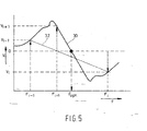
- the goal of the iteration algorithm is to find successive working distances (power settings of the objective lens) which bring the optimum focus closer and closer to the specimen.
- the iteration algorithm to be described here is based on linear interpolation. This algorithm is explained with the aid of Figure 5 , wherein curve 30 shows the course of quantity V as a function of the distance F of the specimen to the optimum focus F opt (the "focus distance"). Contrary to Figure 4 , Figure 5 records the course of curve 30 in a broader vicinity of the zero-crossing of the curve; that is to say that the beginning and end points of curve 30 are situated at a relatively large distance from the optimum focus.
- the algorithm commences with the assumption of an initial power setting of the objective lens whereby the focus distance is represented by F i-1 .
- the value of the focus distance whereby line 32 cuts the horizontal axis is F i+1 ; at this value of the focus distance the attendant value of the quantity V is determined (V i+1 ).
- V i+1 the value of the focus distance whereby line 32 cuts the horizontal axis
- V i+1 the value of the focus distance whereby line 32 cuts the horizontal axis
- a previous measuring point is now selected with which the interpolation is continued; if it appears that the immediately-previous value of V (thus V i ) is opposite in polarity to V i+1 then the interpolation is continued with the measuring point pair (F i , V i ) and (F i+1 , V i+1 ) and otherwise with the measuring point pair (F i-1 , V i-1 ) and (F i , V i ).
- This process of iteration is subsequently repeated until the difference between two successive de-focusing values drops under a pre-stipulated value.
- the focus distance attendant thereto is taken to
- the calculation time required by this algorithm can be considerably shortened by using a subframe of the dataset of an image rather than using the entire dataset.
- the calculation burden upon the algorithm can be reduced considerably thereby, whereby a faster focusing of the beam can be achieved.
- the formation of the subframe can take place by selecting a region in the image with a high information-content; that is to say a region within which a lot of detail in the image can be resolved, which means that a high spectral energy content is present therein.
- the further manipulations of the method according to the invention can now be carried out with this sub-region.
Landscapes
- Chemical & Material Sciences (AREA)
- Analytical Chemistry (AREA)
- Analysing Materials By The Use Of Radiation (AREA)
- Image Processing (AREA)
Claims (7)
- Procédé de focalisation d'un faisceau de particules chargées électriquement dans un dispositif optique à particules comportant un objectif d'imagerie, comportant les étapes :a) former à partir du faisceau précité un premier faisceau pour un premier réglage de l'objectif ;b) former une image, grâce au premier faisceau, d'un spécimen dans le dispositif optique à particules ;c) déterminer la direction du phénomène de traînée astigmatique de l'image formée au cours de l'étape (b) ;d) prévoir un réglage différent de l'objectif ;e) former un second faisceau à partir du faisceau précité, pour l'autre réglage de l'objectif ;f) former une image du spécimen avec le second faisceau ;g) déterminer la direction du phénomène de traînée astigmatique dans l'image formée au cours de l'étape (f) ;h) comparer la direction du phénomène de traînée astigmatique dans l'image formée au cours de l'étape (b) à celle de l'image formée au cours de l'étape (f) ;caractérisé en ce que
au cours de l'étape a), une quantité d'astigmatisme est introduite, en résultat de laquelle le premier faisceau est un premier faisceau astigmatique avec une direction astigmatique associée pour le premier réglage de l'objectif, et le second faisceau est un second faisceau astigmatique avec une direction astigmatique associée pour l'autre réglage de l'objectif ; eti) répéter les étapes (d) à (h) dans le cas où les directions précitées sont égales, et, dans le cas où les directions précitées ne sont pas égales, effectuer un processus d'interpolation entre le premier réglage de l'objectif et le dernier réglage obtenu de l'objectif de manière à déterminer le réglage de l'objectif auquel le faisceau de particules électriquement chargées atteint son foyer. - Procédé selon la revendication 1, dans lequel la détermination de la direction du phénomène de traînée astigmatique dans une image s'effectue en déterminant le contenu d'énergie spectrale d'une première région spectrale de l'image en question avec une première direction, et du contenu d'énergie spectrale d'une seconde région spectrale de cette image avec une seconde direction perpendiculaire à la première direction, et en déterminant au moins le signe de la différence entre le contenu d'énergie spectrale dans la première région et le contenu d'énergie spectrale dans la seconde région.
- Procédé selon la revendication 2, dans lequel la comparaison de la direction du phénomène de traînée astigmatique dans l'image formée au cours de l'étape (b) à celle de l'image formée au cours de l'étape (f) s'effectue en comparant les signes de la différence dans le contenu d'énergie spectrale de la première région et du contenu d'énergie spectrale de la seconde région de chacune des images.
- Procédé selon la revendication 1, dans lequel :j) pour le premier réglage de l'objectif, un troisième faisceau astigmatique avec une direction astigmatique connue perpendiculaire à la direction astigmatique du premier faisceau astigmatique est formé, et une première image du spécimen est formée avec le premier faisceau astigmatique et une troisième image du spécimen est formée avec le troisième faisceau astigmatique ;k) pour le second réglage de l'objectif, un quatrième faisceau astigmatique avec une direction astigmatique connue perpendiculaire à la direction astigmatique du second faisceau astigmatique est formé, et une seconde image du spécimen est formée avec le second faisceau astigmatique et une quatrième image du spécimen est formée avec le quatrième faisceau astigmatique ;l) dans les quatre images ainsi formées, la direction du phénomène de traînée astigmatique est déterminée en déterminant le contenu d'énergie spectrale d'une première région spectrale de l'image en question avec une première direction, et en déterminant le contenu d'énergie spectrale d'une seconde région spectrale de cette image avec une seconde direction perpendiculaire à la première direction, où, dans chaque image, au moins le signe de la différence entre le contenu d'énergie spectrale de la première région et le contenu d'énergie spectrale de la seconde région est déterminé dans laquelle la troisième image peut être formée avant la seconde image.
- Procédé selon l'une quelconque des revendications 2 à 4, dans lequel l'exécution du processus d'interpolation entre le premier réglage de l'objectif et le dernier réglage obtenu de l'objectif est effectuée de sorte que:m) l'amplitude de la différence entre le contenu d'énergie spectrale dans la première région et le contenu d'énergie spectrale dans la seconde région dans chacune des images annexées est déterminée.n) En effectuant une interpolation de ces valeurs, une estimation est obtenue pour la valeur du réglage de l'objectif où le faisceau de particules chargées électriquement atteint sa concentration optimale.o) Une nouvelle image est formée selon le réglage ainsi estimé lorsque l'étape (m) est effectuée, après quoi l'ensemble des valeurs obtenues selon ce nouveau réglage sont utilisées en tant que nouvelles valeurs grâce auxquelles une interpolation est de nouveau effectuée.p) La dernière étape mentionnée est répétée jusqu'à ce que la différence entre deux valeurs consécutives du réglage de l'objectif soit inférieure à une valeur prédéterminée, après quoi la dernière valeur obtenue est conservée pour être le réglage de l'objectif où le faisceau de particules chargées électriquement atteint sa concentration optimum.
- Procédé selon la revendication 5, dans lequel une valeur différente de l'astigmatisme est déterminée en plus pour l'image formée associée à l'étape (o).
- Procédé selon l'une des revendications 2 à 6, dans lequel le traitement d'image est effectué sous forme numérique, et dans lequel une sous-trame de l'image en question est formée afin de déterminer le contenu d'énergie spectrale des régions spectrales précitées.
Applications Claiming Priority (2)
| Application Number | Priority Date | Filing Date | Title |
|---|---|---|---|
| NL1024192 | 2003-08-29 | ||
| NL1024192A NL1024192C2 (nl) | 2003-08-29 | 2003-08-29 | Werkwijze voor het focusseren in een deeltjes-optisch toestel met behulp van astigmatisme in de deeltjesbundel. |
Publications (2)
| Publication Number | Publication Date |
|---|---|
| EP1511065A1 EP1511065A1 (fr) | 2005-03-02 |
| EP1511065B1 true EP1511065B1 (fr) | 2012-04-11 |
Family
ID=34102053
Family Applications (1)
| Application Number | Title | Priority Date | Filing Date |
|---|---|---|---|
| EP04077317A Expired - Fee Related EP1511065B1 (fr) | 2003-08-29 | 2004-08-16 | Méthode pour la focalisation d'un appareil à faisceau de particules chargées à l'aide de l'astigmatisme du faisceau de particules chargées |
Country Status (5)
| Country | Link |
|---|---|
| US (1) | US6992289B2 (fr) |
| EP (1) | EP1511065B1 (fr) |
| JP (1) | JP4868723B2 (fr) |
| CN (1) | CN100585786C (fr) |
| NL (1) | NL1024192C2 (fr) |
Cited By (1)
| Publication number | Priority date | Publication date | Assignee | Title |
|---|---|---|---|---|
| TWI749481B (zh) * | 2019-04-12 | 2021-12-11 | 美商應用材料股份有限公司 | 自動聚焦帶電粒子束於樣本的表面區上的方法、計算帶電粒子束裝置的影像的銳利度值的收斂集合的方法、及用以攝像樣本的帶電粒子束裝置 |
Families Citing this family (14)
| Publication number | Priority date | Publication date | Assignee | Title |
|---|---|---|---|---|
| WO2005074002A2 (fr) * | 2004-01-29 | 2005-08-11 | Applied Materials Israel, Ltd. | Systeme et procede de focalisation pour systeme d'imagerie de particules chargees |
| KR100703980B1 (ko) * | 2005-08-11 | 2007-04-04 | 신동호 | 세라믹 필터의 제조방법 및 이를 이용한 세라믹 필터 |
| EP1780764A1 (fr) * | 2005-11-01 | 2007-05-02 | FEI Company | Ensemble d'étages, appareil d'optique corpusculaire comprenant un tel ensemble d'étages, et procédé de traitement d'un échantillon dans un tel appareil |
| JP4771539B2 (ja) * | 2006-07-26 | 2011-09-14 | キヤノン株式会社 | 画像処理装置及びその制御方法及びプログラム |
| JP4974059B2 (ja) * | 2008-02-15 | 2012-07-11 | 横河電機株式会社 | 自動焦点制御システム |
| US8760563B2 (en) | 2010-10-19 | 2014-06-24 | Hand Held Products, Inc. | Autofocusing optical imaging device |
| US8692927B2 (en) | 2011-01-19 | 2014-04-08 | Hand Held Products, Inc. | Imaging terminal having focus control |
| CN103688333B (zh) * | 2011-02-18 | 2016-10-19 | 应用材料以色列公司 | 聚焦带电粒子成像系统 |
| EP2511936B1 (fr) | 2011-04-13 | 2013-10-02 | Fei Company | Correction d'astigmatisme sans distorsion d'un TEM |
| EP2584584A1 (fr) | 2011-10-19 | 2013-04-24 | FEI Company | Procédé d'ajustement d'un METB équipé d'un correcteur d'aberrations |
| EP2704177B1 (fr) * | 2012-09-04 | 2014-11-26 | Fei Company | Procédé d'investigation et de correction des aberrations dans un système de lentilles à particules chargées |
| EP2722868B1 (fr) * | 2012-10-16 | 2018-02-21 | ICT Integrated Circuit Testing Gesellschaft für Halbleiterprüftechnik mbH | Dispositif octopolaire et procédé d'amélioration de la taille du point |
| EP3651182A1 (fr) * | 2018-11-12 | 2020-05-13 | FEI Company | Microscope à particules chargées servant à l'examen d'un échantillon et procédé de détermination d'une aberration dudit microscope à particules chargées |
| JP7187384B2 (ja) * | 2019-05-17 | 2022-12-12 | 株式会社日立製作所 | 検査装置 |
Family Cites Families (6)
| Publication number | Priority date | Publication date | Assignee | Title |
|---|---|---|---|---|
| JPH03194839A (ja) | 1989-12-25 | 1991-08-26 | Hitachi Ltd | 電子顕微鏡における焦点調整方法及び非点収差補正方法 |
| JP3402868B2 (ja) * | 1995-09-14 | 2003-05-06 | 株式会社東芝 | 荷電粒子光学鏡筒における非点収差の補正及び焦点合わせ方法 |
| JP3994691B2 (ja) * | 2001-07-04 | 2007-10-24 | 株式会社日立製作所 | 荷電粒子線装置および自動非点収差調整方法 |
| US6825480B1 (en) * | 1999-06-23 | 2004-11-30 | Hitachi, Ltd. | Charged particle beam apparatus and automatic astigmatism adjustment method |
| JP3984019B2 (ja) * | 2001-10-15 | 2007-09-26 | パイオニア株式会社 | 電子ビーム装置及び電子ビーム調整方法 |
| JP2005063678A (ja) * | 2003-08-11 | 2005-03-10 | Jeol Ltd | 荷電粒子ビーム装置における自動焦点補正方法および自動非点補正方法 |
-
2003
- 2003-08-29 NL NL1024192A patent/NL1024192C2/nl not_active IP Right Cessation
-
2004
- 2004-08-16 EP EP04077317A patent/EP1511065B1/fr not_active Expired - Fee Related
- 2004-08-27 CN CN200410083277A patent/CN100585786C/zh not_active Expired - Fee Related
- 2004-08-27 US US10/928,573 patent/US6992289B2/en active Active
- 2004-08-27 JP JP2004248701A patent/JP4868723B2/ja not_active Expired - Fee Related
Cited By (1)
| Publication number | Priority date | Publication date | Assignee | Title |
|---|---|---|---|---|
| TWI749481B (zh) * | 2019-04-12 | 2021-12-11 | 美商應用材料股份有限公司 | 自動聚焦帶電粒子束於樣本的表面區上的方法、計算帶電粒子束裝置的影像的銳利度值的收斂集合的方法、及用以攝像樣本的帶電粒子束裝置 |
Also Published As
| Publication number | Publication date |
|---|---|
| US20050045831A1 (en) | 2005-03-03 |
| US6992289B2 (en) | 2006-01-31 |
| JP4868723B2 (ja) | 2012-02-01 |
| NL1024192C2 (nl) | 2005-03-01 |
| EP1511065A1 (fr) | 2005-03-02 |
| CN100585786C (zh) | 2010-01-27 |
| CN1591761A (zh) | 2005-03-09 |
| JP2005079100A (ja) | 2005-03-24 |
Similar Documents
| Publication | Publication Date | Title |
|---|---|---|
| EP1511065B1 (fr) | Méthode pour la focalisation d'un appareil à faisceau de particules chargées à l'aide de l'astigmatisme du faisceau de particules chargées | |
| JP4690625B2 (ja) | 幾何光学収差を決定する方法 | |
| EP1646067B1 (fr) | Appareil à faisceau de particules chargées et procédé pour la mesure de la dimension des motifs | |
| US20110187847A1 (en) | Scanning type charged particle microscope device and method for processing image acquired with scanning type charged particle microscope device | |
| US7714286B2 (en) | Charged particle beam apparatus, aberration correction value calculation unit therefor, and aberration correction program therefor | |
| JP7140854B2 (ja) | 荷電粒子のビームを検査するための方法および装置 | |
| Villarrubia et al. | Simulation study of repeatability and bias in the CD-SEM | |
| US8168956B2 (en) | Scanning transmission electron microscope and method of aberration correction therefor | |
| JP2008159286A (ja) | プローブ評価方法 | |
| Yonekura et al. | Electron energy filtering significantly improves amplitude contrast of frozen-hydrated protein at 300 kV | |
| US5144129A (en) | Electron microscope | |
| CN113720865A (zh) | 自动矫正样品带轴偏离的电子层叠成像方法及装置 | |
| US9076630B2 (en) | Electron microscope and a method for measuring the defocus variation or the limit resolution | |
| Ong et al. | A robust focusing and astigmatism correction method for the scanning electron microscope | |
| EP3172757B1 (fr) | Procédé pour correction automatique de l'astigmatisme | |
| Baba et al. | An auto-tuning method for focusing and astigmatism correction in HAADF-STEM, based on the image contrast transfer function | |
| CN117981040A (zh) | 确定聚焦带电粒子束的束汇聚度的方法和带电粒子束系统 | |
| JP2014106388A (ja) | 自動合焦点検出装置及びそれを備える荷電粒子線顕微鏡 | |
| Tanaka et al. | Influence of electron incident angle distribution on CD-SEM linewidth measurements | |
| US20230352268A1 (en) | Methods of determining aberrations of a charged particle beam, and charged particle beam system | |
| de Isidro Gómez | Image processing algorithms for the determination of the optical aberrations of an electron microscope | |
| Zhu et al. | Deep learning-assisted analysis of HRTEM images of crystalline nanoparticles | |
| KR20240067990A (ko) | 집속된 하전 입자 빔의 빔 수렴을 결정하는 방법, 및 하전 입자 빔 시스템 | |
| WO2023061651A1 (fr) | Procédés de détermination d'aberrations d'un faisceau de particules chargées, et système de faisceau de particules chargées | |
| KR20240067992A (ko) | 하전 입자 빔의 수차들을 결정하는 방법들, 및 하전 입자 빔 시스템 |
Legal Events
| Date | Code | Title | Description |
|---|---|---|---|
| PUAI | Public reference made under article 153(3) epc to a published international application that has entered the european phase |
Free format text: ORIGINAL CODE: 0009012 |
|
| 17P | Request for examination filed |
Effective date: 20040816 |
|
| AK | Designated contracting states |
Kind code of ref document: A1 Designated state(s): AT BE BG CH CY CZ DE DK EE ES FI FR GB GR HU IE IT LI LU MC NL PL PT RO SE SI SK TR |
|
| AX | Request for extension of the european patent |
Extension state: AL HR LT LV MK |
|
| RIN1 | Information on inventor provided before grant (corrected) |
Inventor name: VAN VLUCHT, ROBERTUS JOHANNES MICHAEL Inventor name: STERKEN, HENDRIKUS P. M.,PHILIPS RES.LABORATORIES Inventor name: MAES, WILLEM HENDRIK |
|
| AKX | Designation fees paid |
Designated state(s): DE FR GB |
|
| 17Q | First examination report despatched |
Effective date: 20090416 |
|
| GRAP | Despatch of communication of intention to grant a patent |
Free format text: ORIGINAL CODE: EPIDOSNIGR1 |
|
| RIN1 | Information on inventor provided before grant (corrected) |
Inventor name: STERKEN, HENDRIKUS P. M. Inventor name: MAES, WILLEM HENDRIK Inventor name: VAN VLUCHT, ROBERTUS JOHANNES MICHAEL |
|
| GRAS | Grant fee paid |
Free format text: ORIGINAL CODE: EPIDOSNIGR3 |
|
| GRAA | (expected) grant |
Free format text: ORIGINAL CODE: 0009210 |
|
| AK | Designated contracting states |
Kind code of ref document: B1 Designated state(s): DE FR GB |
|
| REG | Reference to a national code |
Ref country code: GB Ref legal event code: FG4D |
|
| REG | Reference to a national code |
Ref country code: DE Ref legal event code: R096 Ref document number: 602004037254 Country of ref document: DE Effective date: 20120606 |
|
| PLBE | No opposition filed within time limit |
Free format text: ORIGINAL CODE: 0009261 |
|
| STAA | Information on the status of an ep patent application or granted ep patent |
Free format text: STATUS: NO OPPOSITION FILED WITHIN TIME LIMIT |
|
| 26N | No opposition filed |
Effective date: 20130114 |
|
| REG | Reference to a national code |
Ref country code: DE Ref legal event code: R097 Ref document number: 602004037254 Country of ref document: DE Effective date: 20130114 |
|
| REG | Reference to a national code |
Ref country code: FR Ref legal event code: PLFP Year of fee payment: 13 |
|
| REG | Reference to a national code |
Ref country code: FR Ref legal event code: PLFP Year of fee payment: 14 |
|
| REG | Reference to a national code |
Ref country code: FR Ref legal event code: PLFP Year of fee payment: 15 |
|
| PGFP | Annual fee paid to national office [announced via postgrant information from national office to epo] |
Ref country code: FR Payment date: 20180712 Year of fee payment: 15 Ref country code: DE Payment date: 20180731 Year of fee payment: 15 |
|
| PGFP | Annual fee paid to national office [announced via postgrant information from national office to epo] |
Ref country code: GB Payment date: 20180815 Year of fee payment: 15 |
|
| REG | Reference to a national code |
Ref country code: DE Ref legal event code: R119 Ref document number: 602004037254 Country of ref document: DE |
|
| GBPC | Gb: european patent ceased through non-payment of renewal fee |
Effective date: 20190816 |
|
| PG25 | Lapsed in a contracting state [announced via postgrant information from national office to epo] |
Ref country code: DE Free format text: LAPSE BECAUSE OF NON-PAYMENT OF DUE FEES Effective date: 20200303 Ref country code: FR Free format text: LAPSE BECAUSE OF NON-PAYMENT OF DUE FEES Effective date: 20190831 |
|
| PG25 | Lapsed in a contracting state [announced via postgrant information from national office to epo] |
Ref country code: GB Free format text: LAPSE BECAUSE OF NON-PAYMENT OF DUE FEES Effective date: 20190816 |