EP1510790B1 - Verfahren und Vorrichtung zur Regelung einer Lichtquelle eines Positionsmessgerätes - Google Patents
Verfahren und Vorrichtung zur Regelung einer Lichtquelle eines Positionsmessgerätes Download PDFInfo
- Publication number
- EP1510790B1 EP1510790B1 EP04011338A EP04011338A EP1510790B1 EP 1510790 B1 EP1510790 B1 EP 1510790B1 EP 04011338 A EP04011338 A EP 04011338A EP 04011338 A EP04011338 A EP 04011338A EP 1510790 B1 EP1510790 B1 EP 1510790B1
- Authority
- EP
- European Patent Office
- Prior art keywords
- photocurrents
- light source
- reference variable
- photodetectors
- variable
- Prior art date
- Legal status (The legal status is an assumption and is not a legal conclusion. Google has not performed a legal analysis and makes no representation as to the accuracy of the status listed.)
- Expired - Lifetime
Links
- 238000000034 method Methods 0.000 title claims abstract description 20
- 230000001105 regulatory effect Effects 0.000 title abstract description 4
- 230000001419 dependent effect Effects 0.000 claims abstract description 37
- 239000000463 material Substances 0.000 claims abstract description 8
- 238000006243 chemical reaction Methods 0.000 claims description 3
- 239000004065 semiconductor Substances 0.000 claims description 2
- 238000005259 measurement Methods 0.000 abstract description 6
- 230000001276 controlling effect Effects 0.000 description 8
- 238000011109 contamination Methods 0.000 description 6
- 230000033228 biological regulation Effects 0.000 description 4
- 230000008859 change Effects 0.000 description 3
- 238000011156 evaluation Methods 0.000 description 2
- 230000003287 optical effect Effects 0.000 description 2
- 241000669003 Aspidiotus destructor Species 0.000 description 1
- 230000032683 aging Effects 0.000 description 1
- 238000010276 construction Methods 0.000 description 1
- 230000007423 decrease Effects 0.000 description 1
- 230000000694 effects Effects 0.000 description 1
- 230000006870 function Effects 0.000 description 1
- 239000007788 liquid Substances 0.000 description 1
- 230000004048 modification Effects 0.000 description 1
- 238000012986 modification Methods 0.000 description 1
- 230000009467 reduction Effects 0.000 description 1
- 230000009466 transformation Effects 0.000 description 1
- 230000001960 triggered effect Effects 0.000 description 1
Images

Classifications
-
- G—PHYSICS
- G01—MEASURING; TESTING
- G01D—MEASURING NOT SPECIALLY ADAPTED FOR A SPECIFIC VARIABLE; ARRANGEMENTS FOR MEASURING TWO OR MORE VARIABLES NOT COVERED IN A SINGLE OTHER SUBCLASS; TARIFF METERING APPARATUS; MEASURING OR TESTING NOT OTHERWISE PROVIDED FOR
- G01D5/00—Mechanical means for transferring the output of a sensing member; Means for converting the output of a sensing member to another variable where the form or nature of the sensing member does not constrain the means for converting; Transducers not specially adapted for a specific variable
- G01D5/26—Mechanical means for transferring the output of a sensing member; Means for converting the output of a sensing member to another variable where the form or nature of the sensing member does not constrain the means for converting; Transducers not specially adapted for a specific variable characterised by optical transfer means, i.e. using infrared, visible, or ultraviolet light
- G01D5/32—Mechanical means for transferring the output of a sensing member; Means for converting the output of a sensing member to another variable where the form or nature of the sensing member does not constrain the means for converting; Transducers not specially adapted for a specific variable characterised by optical transfer means, i.e. using infrared, visible, or ultraviolet light with attenuation or whole or partial obturation of beams of light
- G01D5/34—Mechanical means for transferring the output of a sensing member; Means for converting the output of a sensing member to another variable where the form or nature of the sensing member does not constrain the means for converting; Transducers not specially adapted for a specific variable characterised by optical transfer means, i.e. using infrared, visible, or ultraviolet light with attenuation or whole or partial obturation of beams of light the beams of light being detected by photocells
- G01D5/36—Forming the light into pulses
Definitions
- the invention relates to a device for controlling a light source in a position measuring device according to the preamble of claim 1 and a corresponding method according to claim 6.
- light sources are often used whose light is modulated position-dependent by a corresponding material measure, for example in the form of a scale or a slice.
- the modulated light is usually converted by photodetectors into electrical photocurrents, so that the relative position between the light source and the material measure from these position-dependent photocurrents can be determined.
- a method and apparatus for controlling such a light source will be described.
- the sum of the position-dependent photocurrents is formed there in a control loop as the actual size of the light intensity.
- This actual size is then compared with a fixed, fixed predetermined target size, thereby determining the control difference for controlling the light source.
- Such a control device has the disadvantage that no contamination or only inaccurate or unstable position measurement is possible in the event of contamination, in particular in the case of large-scale contamination of the material measure.
- the invention is therefore based on the object to provide an apparatus and a method by which a safe, robust, in particular insensitive to contamination position measurement with high accuracy is possible.
- the setpoint quantity which is decisive for the regulation of a light source is generated based on position-dependent photocurrents, the position-dependent photocurrents being produced by conversion of modulated light of the light source by means of photodetectors.
- the actual size required for determining the control difference for controlling the light source is formed based on position-dependent or position-independent photo currents.
- the photodetectors and a means for generating the desired size are accommodated on one and the same ASIC.
- electrical signals are first digitized with an analog-to-digital converter to determine the desired size, which are based on position-dependent photocurrents. Afterwards, these digital values are processed further.
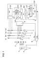
- a position measuring device with the control according to the invention is shown schematically.
- a light source is shown, which is formed in the illustrated embodiment as an LED 1.
- the LED 1 opposite is a material measure in the form of a transparent scale 2, are applied to the opaque division lines.
- the position measuring device on four photodetectors 3, wherein the scale 2 between the photodetectors 3 and the LED 1 is located.
- the photodetectors 3 are integrated in the example shown in a semiconductor element, in particular an ASIC.
- the scale 2 is displaceable relative to the LED 1 in the direction of the double arrow in FIGS. 1 and 2, the relative position between scale 2 and LED 1 being measured by the position measuring device.
- the light emitted by the LED 1 is modulated position-dependent by the scale 2 and converted in the photodetectors 3 in position-dependent photocurrents I 0 ° , I 90 ° , I 180 ° , I 270 ° .
- the position-dependent photocurrents I 0 ° , I 90 ° , I 180 ° , I 270 ° produced in this way ideally have a sinusoidal profile and have a phase offset of 90 ° in each case.
- the position-dependent photocurrents I 0 ° , I 90 ° , I 180 ° , I 270 ° are then further processed in a, not shown in the figures, evaluation, so that from them ultimately the position to be determined position data are generated.
- the invention is not limited to arrangements in which exactly four photodetectors 3 are used, or in which four photocurrents I 0 ° , I 90 ° , I 190 °, I 270 ° are evaluated.
- two or three photodetectors and correspondingly two or three position-dependent photocurrents can also be used for the evaluation.
- the average photocurrent which is formed from the sum of all position-dependent photocurrents I 0 ° , I 90 ° , I 180 ° , I 270 ° , is ideally constant. But if, for example, the intensity of the LED 1 decreases, the average photocurrent will also be reduced. In particular, if the scale 2 is contaminated, for example by a liquid film, it may be that the average of the position-dependent photocurrents I 0 ° , I 90 ° , I 180 ° , I 270 ° remains virtually unchanged from the ideal case, but the Degree of modulation of the position-dependent photocurrents I 0 ° , I 90 ° , I 180 ° , I 270 ° greatly reduced.
- a total voltage is according to FIG 1 with a sum generator 4 by an analogous procedure based on the position-dependent photocurrents formed at the same time as the actual value U 4 in Control circuit for controlling the intensity of the LED 1 is used.
- This actual variable U 4 is then supplied to a comparator, which is designed in the form of a differential amplifier 6, and used there as an actual value for the regulation of the LED 1.
- the required magnitude U 5 required for the regulation of the intensity of the LED 1 is determined by means of a means for generating a desired value U 5 , in the example shown with the aid of a circuit 5.
- the setpoint value U 5 can be seen as an electrical voltage.
- the circuit 5 is located on the same ASIC on which the photodetectors 3 are also arranged.
- These electrical signals in the form of the photo voltages U 0 ° , U 90 ° , U 180 ° , U 270 ° , which consequently on the position-dependent photocurrents I 0 ° , I 90 ° , I 180 ° , I 270 ° . are then digitized in an analog-to-digital converter 5.2, that is converted into digital values.
- an already stored value of a desired pointer length SL is read from a memory element, here an EPROM 5.4.
- the desired pointer length SL is already in the configuration of the position measuring device, ie before the actual measuring insert, permanently stored. The value of the desired pointer length SL is then no longer changed over the entire lifetime of the position measuring device.
- This new setpoint value Y ' is then converted in a digital-to-analogue converter 5.8 into an analogue nominal value U 5 (electrical voltage) which, as described above, is dependent on the position-dependent photocurrents I 0 ° , I 90 ° , I 180 ° , I 270 ° based.
- the so-called summation current method can be used in which the pointer length S based on the sum of the position-dependent photocurrents I 0 ° , I 90 ° , I 180 ° , I 270 ° determined becomes.
- the analog target size U 5 is then supplied to the differential amplifier 6, where it is compared with the actual size U 4 , so that a control difference for controlling the intensity of the LED 1 is generated.
- the control difference which also represents a voltage in physical terms, is applied to a steeping member, in the exemplary embodiment shown, to a transistor 7, in particular at the base of the transistor 7.
- the height or amplitude of the current that is fed into the LED 1 adjusts.
- the intensity of the light emitted by the LED 1 is known to be a function of the level of the current fed into the LED 1.
- a corresponding nominal value Y is set stored in the setpoint memory 5.7 over a certain time.
- the setpoint value Y will remain unchanged until the next time the position measuring device is switched on. This means that from this point until the next switch-on of the position measuring device, the circuit elements shown in dashed lines are no longer active.
- the setpoint value U 5 is checked in each case after the position measuring device is switched on and, if necessary, a corresponding value Y is stored after several iteration steps, so that the setpoint value U 5 until the next switch-on operation in the control loop for regulating the intensity of the LED 1 remains unchanged.
- the desired value Y can also be checked permanently during the operation of the position measuring device.
- a support point-dependent determination of the setpoint value Y at predetermined time intervals, for. B. every 68 microseconds are made, or else be position-dependent, z. B. the setpoint Y every 100 signal periods can be determined.
- control can also be configured so that when the comparator 5.6 detects a too large difference ⁇ between the actual pointer length S and the predetermined value of the setpoint pointer length SL during operation, only one alarm is triggered during operation. In the case of the alarm then the position measuring device is to be restarted, so that thus the renewed fixing or storing a changed Setpoint value Y in setpoint memory 5.7 is carried out with the startup procedure.
- the photodetectors 3, 8 are arranged such that light modulated by a part number of the photodetectors of the scale 2 is converted into position-dependent photocurrents I 0 ° , I 90 ° , I 180 ° , I 270 ° .
- the determination of the target size U 5 is therefore based only on photo currents I 0 ° , I 90 ° , I 180 , I 270 ° a part number of the photodetectors, namely the photodetectors 3.
- the target size U 5 with the same circuit 5 as determined in the first embodiment.
- the non-modulated light of the LED 1 is converted by a photodetector 8 into a photocurrent, this photocurrent representing the basis for the actual quantity U 8 . That is, for the regulation of the intensity of the LED 1, an actual quantity U 8 is used, which is ultimately generated by the photodetector 8, which receives light emitted by the LED 1 which is not position-modulated by the scale 2.
- the actual size U 8 is then supplied to the differential amplifier 6, as in the first embodiment, where a comparison between the actual size U 8 and the target size U 5 is performed, so that a control difference for controlling the intensity of the LED 1 is determined.
- the control difference is applied in the form of a voltage to the base of the transistor 7, so that the LED 1 is ultimately supplied with an electric current, the amount of which depends on the control difference.
- the desired value U 5 is determined in each case by a digital method.
- the invention also includes Arrangements and methods in which the target size U 5 is determined by an analog circuit.
Landscapes
- Physics & Mathematics (AREA)
- General Physics & Mathematics (AREA)
- Length Measuring Devices By Optical Means (AREA)
- Optical Transform (AREA)
- Formation Of Various Coating Films On Cathode Ray Tubes And Lamps (AREA)
Applications Claiming Priority (2)
| Application Number | Priority Date | Filing Date | Title |
|---|---|---|---|
| DE10339366 | 2003-08-27 | ||
| DE10339366A DE10339366A1 (de) | 2003-08-27 | 2003-08-27 | Verfahren und Vorrichtung zur Regelung einer Lichtquelle eines Positionsmessgerätes |
Publications (2)
| Publication Number | Publication Date |
|---|---|
| EP1510790A1 EP1510790A1 (de) | 2005-03-02 |
| EP1510790B1 true EP1510790B1 (de) | 2007-08-22 |
Family
ID=34089208
Family Applications (1)
| Application Number | Title | Priority Date | Filing Date |
|---|---|---|---|
| EP04011338A Expired - Lifetime EP1510790B1 (de) | 2003-08-27 | 2004-05-13 | Verfahren und Vorrichtung zur Regelung einer Lichtquelle eines Positionsmessgerätes |
Country Status (7)
Cited By (1)
| Publication number | Priority date | Publication date | Assignee | Title |
|---|---|---|---|---|
| DE102008008584A1 (de) | 2008-02-12 | 2009-08-13 | Bayerische Motoren Werke Aktiengesellschaft | Gleitlagerschale |
Families Citing this family (5)
| Publication number | Priority date | Publication date | Assignee | Title |
|---|---|---|---|---|
| JP2005291734A (ja) * | 2004-03-31 | 2005-10-20 | Univ Nagoya | 森林内光環境測定装置 |
| US8772705B2 (en) * | 2010-12-01 | 2014-07-08 | Avago Technologies General Ip (Singapore) Pte. Ltd. | Interpolation circuitry for optical encoders |
| DE102012108815A1 (de) | 2012-09-19 | 2014-03-20 | Ic-Haus Gmbh | Verfahren zur Einstellung des Arbeitspunkts einer Positionsmessvorrichtung und Schaltungsanordnung |
| CN103148779B (zh) * | 2013-01-30 | 2016-01-13 | 中国科学院长春光学精密机械与物理研究所 | 位置测量设备中光源的调整装置 |
| DE102013222383A1 (de) | 2013-02-06 | 2014-08-07 | Dr. Johannes Heidenhain Gmbh | Optische Positionsmesseinrichtung |
Family Cites Families (13)
| Publication number | Priority date | Publication date | Assignee | Title |
|---|---|---|---|---|
| DE2730056A1 (de) * | 1977-07-02 | 1979-01-18 | Int Standard Electric Corp | Regler fuer einen lichtsender |
| GB2054135B (en) | 1979-07-19 | 1984-03-14 | Burroughs Corp | Photo-electric displacement transducer |
| US4593194A (en) * | 1983-10-05 | 1986-06-03 | Quantum Corporation | Optical encoder with digital gain compensation controlling source intensity |
| US5015836A (en) * | 1990-02-05 | 1991-05-14 | Bei Electronics, Inc. | Source intensity adjustment apparatus for optical channel |
| JPH05256665A (ja) | 1992-03-13 | 1993-10-05 | Canon Inc | エンコーダー |
| JP3312045B2 (ja) * | 1992-09-25 | 2002-08-05 | オリンパス光学工業株式会社 | ファインダー光学系の接眼レンズ |
| JP3170902B2 (ja) * | 1992-09-30 | 2001-05-28 | キヤノン株式会社 | 信号処理方法及びそれを用いたエンコーダ |
| JPH0783612A (ja) | 1993-09-17 | 1995-03-28 | Canon Inc | 光学式変位センサ |
| US6492637B1 (en) * | 1999-05-10 | 2002-12-10 | Citizen Watch Co., Ltd. | Dimension measuring device |
| US6344641B1 (en) * | 1999-08-11 | 2002-02-05 | Agilent Technologies, Inc. | System and method for on-chip calibration of illumination sources for an integrated circuit display |
| JP2001311630A (ja) | 2000-02-22 | 2001-11-09 | Mitsutoyo Corp | 光学式エンコーダ |
| US6380352B1 (en) * | 2000-08-29 | 2002-04-30 | Eastman Chemical Company | Polyester precursor purification process |
| US20030234351A1 (en) * | 2002-06-25 | 2003-12-25 | Chong-Hin Chee | Brightness independent optical position sensor |
-
2003
- 2003-08-27 DE DE10339366A patent/DE10339366A1/de not_active Withdrawn
-
2004
- 2004-05-13 DE DE502004004708T patent/DE502004004708D1/de not_active Expired - Lifetime
- 2004-05-13 AT AT04011338T patent/ATE371169T1/de not_active IP Right Cessation
- 2004-05-13 ES ES04011338T patent/ES2293118T3/es not_active Expired - Lifetime
- 2004-05-13 EP EP04011338A patent/EP1510790B1/de not_active Expired - Lifetime
- 2004-06-24 JP JP2004186662A patent/JP4473054B2/ja not_active Expired - Fee Related
- 2004-08-27 CN CNB2004100682651A patent/CN100408978C/zh not_active Expired - Fee Related
- 2004-08-27 US US10/927,689 patent/US7235776B2/en not_active Expired - Fee Related
Cited By (1)
| Publication number | Priority date | Publication date | Assignee | Title |
|---|---|---|---|---|
| DE102008008584A1 (de) | 2008-02-12 | 2009-08-13 | Bayerische Motoren Werke Aktiengesellschaft | Gleitlagerschale |
Also Published As
| Publication number | Publication date |
|---|---|
| ES2293118T3 (es) | 2008-03-16 |
| US20050052641A1 (en) | 2005-03-10 |
| ATE371169T1 (de) | 2007-09-15 |
| CN1590968A (zh) | 2005-03-09 |
| DE502004004708D1 (de) | 2007-10-04 |
| JP4473054B2 (ja) | 2010-06-02 |
| EP1510790A1 (de) | 2005-03-02 |
| CN100408978C (zh) | 2008-08-06 |
| JP2005070032A (ja) | 2005-03-17 |
| US7235776B2 (en) | 2007-06-26 |
| DE10339366A1 (de) | 2005-03-24 |
Similar Documents
| Publication | Publication Date | Title |
|---|---|---|
| DE69825204T2 (de) | Eigenkalibrierung eines Oszilloskops mittels eines Rechteck-Testsignals | |
| DE3884337T2 (de) | Gerät zur automatischen Kontrolle des Vergrösserungsfaktors in einem Rasterelektronenmikroskop. | |
| EP0085951B1 (de) | Verfahren und Vorrichtung zur Erfassung von Messgrössen | |
| DE69425897T2 (de) | Verfahren und Struktur zur elektronischen Messung des Parameter eines Strahls | |
| DE3417176A1 (de) | Photoelektrische messeinrichtung | |
| DE102018220688A1 (de) | Analog-Digital-Wandler | |
| DE102018113530B4 (de) | Codierer mit der Funktion zur Regulierung des Schwellenwerts eines Vergleichers,sowie Verfahren zur Steuerung des Codierers | |
| DE2814265A1 (de) | Verfahren und vorrichtung zur automatischen korrektur der einstellung eines mikroskops | |
| EP0632262A1 (de) | Verfahren und Anordnung zum Erfassen und Auswerten analoger photometrischer Signale in einem Testträger-Analysesystem | |
| DE102008014411A1 (de) | Signalaufbereitung für einen optischen Codierer | |
| DE4332254C1 (de) | Verwendung eines Abstandssensors für Computertomographen | |
| EP1510790B1 (de) | Verfahren und Vorrichtung zur Regelung einer Lichtquelle eines Positionsmessgerätes | |
| EP0204897B1 (de) | Verfahren und Einrichtung zur Regelung des Tastverhältnisses eines elektrischen Signals | |
| EP1207372B1 (de) | Verfahren und Vorrichtung zur Konditionierung eines periodischen Analogsignals | |
| DE102011114953B4 (de) | Ursprungsort-Detektionsschaltung | |
| EP2197117B1 (de) | Schaltungseinheit zum Erzeugen einer Ausgangsspannung in Abhängigkeit von einem digitalen Datenwert und Verfahren zum Kalibrieren der Schaltungseinheit | |
| DE2327802C3 (de) | Steuerbarer Analogverstärker für einen photoelektrischen Wandler | |
| EP1585234B1 (de) | Photomischdetektor (PMD)-System und Verfahren zum Betreiben desselben | |
| EP0446418B1 (de) | Füllstandsgeber | |
| DE2755038B2 (de) | Analogkomparator | |
| CH669254A5 (de) | Einrichtung zum messen und einstellen von laengen und verwendung der einrichtung. | |
| WO2014095474A1 (de) | Feldgerät mit einem analogausgang | |
| DE19948892A1 (de) | Impulsdetektor und Verfahren zur Detektion von sinusförmigen Impulsen | |
| EP1378063B1 (de) | Verfahren und schaltung zur linearisierung von nichtlinearen kennlinien | |
| EP0456168A2 (de) | Vorrichtung zur Analog-Ditial-Wandlung einer Messgrösse, die von in Brückenschaltung angeordneten Sensoren erzeugt wird, insbesondere von Dehnungsmessstreifen in einer Wägezelle |
Legal Events
| Date | Code | Title | Description |
|---|---|---|---|
| PUAI | Public reference made under article 153(3) epc to a published international application that has entered the european phase |
Free format text: ORIGINAL CODE: 0009012 |
|
| AK | Designated contracting states |
Kind code of ref document: A1 Designated state(s): AT BE BG CH CY CZ DE DK EE ES FI FR GB GR HU IE IT LI LU MC NL PL PT RO SE SI SK TR |
|
| AX | Request for extension of the european patent |
Extension state: AL HR LT LV MK |
|
| 17P | Request for examination filed |
Effective date: 20050902 |
|
| AKX | Designation fees paid |
Designated state(s): AT BE BG CH CY CZ DE DK EE ES FI FR GB GR HU IE IT LI LU MC NL PL PT RO SE SI SK TR |
|
| GRAP | Despatch of communication of intention to grant a patent |
Free format text: ORIGINAL CODE: EPIDOSNIGR1 |
|
| GRAS | Grant fee paid |
Free format text: ORIGINAL CODE: EPIDOSNIGR3 |
|
| GRAA | (expected) grant |
Free format text: ORIGINAL CODE: 0009210 |
|
| AK | Designated contracting states |
Kind code of ref document: B1 Designated state(s): AT BE BG CH CY CZ DE DK EE ES FI FR GB GR HU IE IT LI LU MC NL PL PT RO SE SI SK TR |
|
| REG | Reference to a national code |
Ref country code: GB Ref legal event code: FG4D Free format text: NOT ENGLISH |
|
| GBT | Gb: translation of ep patent filed (gb section 77(6)(a)/1977) |
Effective date: 20070822 |
|
| REG | Reference to a national code |
Ref country code: CH Ref legal event code: EP |
|
| REG | Reference to a national code |
Ref country code: IE Ref legal event code: FG4D Free format text: LANGUAGE OF EP DOCUMENT: GERMAN |
|
| REG | Reference to a national code |
Ref country code: CH Ref legal event code: NV Representative=s name: TROESCH SCHEIDEGGER WERNER AG |
|
| REF | Corresponds to: |
Ref document number: 502004004708 Country of ref document: DE Date of ref document: 20071004 Kind code of ref document: P |
|
| PG25 | Lapsed in a contracting state [announced via postgrant information from national office to epo] |
Ref country code: BG Free format text: LAPSE BECAUSE OF FAILURE TO SUBMIT A TRANSLATION OF THE DESCRIPTION OR TO PAY THE FEE WITHIN THE PRESCRIBED TIME-LIMIT Effective date: 20071122 Ref country code: FI Free format text: LAPSE BECAUSE OF FAILURE TO SUBMIT A TRANSLATION OF THE DESCRIPTION OR TO PAY THE FEE WITHIN THE PRESCRIBED TIME-LIMIT Effective date: 20070822 Ref country code: NL Free format text: LAPSE BECAUSE OF FAILURE TO SUBMIT A TRANSLATION OF THE DESCRIPTION OR TO PAY THE FEE WITHIN THE PRESCRIBED TIME-LIMIT Effective date: 20070822 |
|
| NLV1 | Nl: lapsed or annulled due to failure to fulfill the requirements of art. 29p and 29m of the patents act | ||
| PG25 | Lapsed in a contracting state [announced via postgrant information from national office to epo] |
Ref country code: PL Free format text: LAPSE BECAUSE OF FAILURE TO SUBMIT A TRANSLATION OF THE DESCRIPTION OR TO PAY THE FEE WITHIN THE PRESCRIBED TIME-LIMIT Effective date: 20070822 |
|
| REG | Reference to a national code |
Ref country code: ES Ref legal event code: FG2A Ref document number: 2293118 Country of ref document: ES Kind code of ref document: T3 |
|
| REG | Reference to a national code |
Ref country code: IE Ref legal event code: FD4D |
|
| EN | Fr: translation not filed | ||
| PG25 | Lapsed in a contracting state [announced via postgrant information from national office to epo] |
Ref country code: GR Free format text: LAPSE BECAUSE OF FAILURE TO SUBMIT A TRANSLATION OF THE DESCRIPTION OR TO PAY THE FEE WITHIN THE PRESCRIBED TIME-LIMIT Effective date: 20071123 Ref country code: DK Free format text: LAPSE BECAUSE OF FAILURE TO SUBMIT A TRANSLATION OF THE DESCRIPTION OR TO PAY THE FEE WITHIN THE PRESCRIBED TIME-LIMIT Effective date: 20070822 |
|
| PG25 | Lapsed in a contracting state [announced via postgrant information from national office to epo] |
Ref country code: SK Free format text: LAPSE BECAUSE OF FAILURE TO SUBMIT A TRANSLATION OF THE DESCRIPTION OR TO PAY THE FEE WITHIN THE PRESCRIBED TIME-LIMIT Effective date: 20070822 Ref country code: IE Free format text: LAPSE BECAUSE OF FAILURE TO SUBMIT A TRANSLATION OF THE DESCRIPTION OR TO PAY THE FEE WITHIN THE PRESCRIBED TIME-LIMIT Effective date: 20070822 Ref country code: PT Free format text: LAPSE BECAUSE OF FAILURE TO SUBMIT A TRANSLATION OF THE DESCRIPTION OR TO PAY THE FEE WITHIN THE PRESCRIBED TIME-LIMIT Effective date: 20080122 |
|
| PLBE | No opposition filed within time limit |
Free format text: ORIGINAL CODE: 0009261 |
|
| STAA | Information on the status of an ep patent application or granted ep patent |
Free format text: STATUS: NO OPPOSITION FILED WITHIN TIME LIMIT |
|
| PG25 | Lapsed in a contracting state [announced via postgrant information from national office to epo] |
Ref country code: SE Free format text: LAPSE BECAUSE OF FAILURE TO SUBMIT A TRANSLATION OF THE DESCRIPTION OR TO PAY THE FEE WITHIN THE PRESCRIBED TIME-LIMIT Effective date: 20071122 Ref country code: RO Free format text: LAPSE BECAUSE OF FAILURE TO SUBMIT A TRANSLATION OF THE DESCRIPTION OR TO PAY THE FEE WITHIN THE PRESCRIBED TIME-LIMIT Effective date: 20070822 |
|
| 26N | No opposition filed |
Effective date: 20080526 |
|
| BERE | Be: lapsed |
Owner name: DR. JOHANNES HEIDENHAIN G.M.B.H. Effective date: 20080531 |
|
| PG25 | Lapsed in a contracting state [announced via postgrant information from national office to epo] |
Ref country code: MC Free format text: LAPSE BECAUSE OF NON-PAYMENT OF DUE FEES Effective date: 20080531 |
|
| PG25 | Lapsed in a contracting state [announced via postgrant information from national office to epo] |
Ref country code: EE Free format text: LAPSE BECAUSE OF FAILURE TO SUBMIT A TRANSLATION OF THE DESCRIPTION OR TO PAY THE FEE WITHIN THE PRESCRIBED TIME-LIMIT Effective date: 20070822 |
|
| PG25 | Lapsed in a contracting state [announced via postgrant information from national office to epo] |
Ref country code: BE Free format text: LAPSE BECAUSE OF NON-PAYMENT OF DUE FEES Effective date: 20080531 |
|
| PG25 | Lapsed in a contracting state [announced via postgrant information from national office to epo] |
Ref country code: SI Free format text: LAPSE BECAUSE OF FAILURE TO SUBMIT A TRANSLATION OF THE DESCRIPTION OR TO PAY THE FEE WITHIN THE PRESCRIBED TIME-LIMIT Effective date: 20070822 |
|
| PG25 | Lapsed in a contracting state [announced via postgrant information from national office to epo] |
Ref country code: CY Free format text: LAPSE BECAUSE OF FAILURE TO SUBMIT A TRANSLATION OF THE DESCRIPTION OR TO PAY THE FEE WITHIN THE PRESCRIBED TIME-LIMIT Effective date: 20070822 |
|
| PG25 | Lapsed in a contracting state [announced via postgrant information from national office to epo] |
Ref country code: AT Free format text: LAPSE BECAUSE OF NON-PAYMENT OF DUE FEES Effective date: 20080513 |
|
| PG25 | Lapsed in a contracting state [announced via postgrant information from national office to epo] |
Ref country code: LU Free format text: LAPSE BECAUSE OF NON-PAYMENT OF DUE FEES Effective date: 20080513 Ref country code: HU Free format text: LAPSE BECAUSE OF FAILURE TO SUBMIT A TRANSLATION OF THE DESCRIPTION OR TO PAY THE FEE WITHIN THE PRESCRIBED TIME-LIMIT Effective date: 20080223 |
|
| PG25 | Lapsed in a contracting state [announced via postgrant information from national office to epo] |
Ref country code: TR Free format text: LAPSE BECAUSE OF FAILURE TO SUBMIT A TRANSLATION OF THE DESCRIPTION OR TO PAY THE FEE WITHIN THE PRESCRIBED TIME-LIMIT Effective date: 20070822 |
|
| PG25 | Lapsed in a contracting state [announced via postgrant information from national office to epo] |
Ref country code: FR Free format text: LAPSE BECAUSE OF FAILURE TO SUBMIT A TRANSLATION OF THE DESCRIPTION OR TO PAY THE FEE WITHIN THE PRESCRIBED TIME-LIMIT Effective date: 20080418 |
|
| PGFP | Annual fee paid to national office [announced via postgrant information from national office to epo] |
Ref country code: CZ Payment date: 20140509 Year of fee payment: 11 |
|
| PG25 | Lapsed in a contracting state [announced via postgrant information from national office to epo] |
Ref country code: CZ Free format text: LAPSE BECAUSE OF NON-PAYMENT OF DUE FEES Effective date: 20150513 |
|
| PGFP | Annual fee paid to national office [announced via postgrant information from national office to epo] |
Ref country code: CH Payment date: 20180523 Year of fee payment: 15 Ref country code: ES Payment date: 20180625 Year of fee payment: 15 |
|
| PGFP | Annual fee paid to national office [announced via postgrant information from national office to epo] |
Ref country code: IT Payment date: 20180530 Year of fee payment: 15 |
|
| PGFP | Annual fee paid to national office [announced via postgrant information from national office to epo] |
Ref country code: GB Payment date: 20180518 Year of fee payment: 15 |
|
| PGFP | Annual fee paid to national office [announced via postgrant information from national office to epo] |
Ref country code: DE Payment date: 20190521 Year of fee payment: 16 |
|
| REG | Reference to a national code |
Ref country code: CH Ref legal event code: PL |
|
| GBPC | Gb: european patent ceased through non-payment of renewal fee |
Effective date: 20190513 |
|
| PG25 | Lapsed in a contracting state [announced via postgrant information from national office to epo] |
Ref country code: CH Free format text: LAPSE BECAUSE OF NON-PAYMENT OF DUE FEES Effective date: 20190531 Ref country code: LI Free format text: LAPSE BECAUSE OF NON-PAYMENT OF DUE FEES Effective date: 20190531 |
|
| PG25 | Lapsed in a contracting state [announced via postgrant information from national office to epo] |
Ref country code: GB Free format text: LAPSE BECAUSE OF NON-PAYMENT OF DUE FEES Effective date: 20190513 Ref country code: IT Free format text: LAPSE BECAUSE OF NON-PAYMENT OF DUE FEES Effective date: 20190513 |
|
| REG | Reference to a national code |
Ref country code: ES Ref legal event code: FD2A Effective date: 20200928 |
|
| PG25 | Lapsed in a contracting state [announced via postgrant information from national office to epo] |
Ref country code: ES Free format text: LAPSE BECAUSE OF NON-PAYMENT OF DUE FEES Effective date: 20190514 |
|
| REG | Reference to a national code |
Ref country code: DE Ref legal event code: R119 Ref document number: 502004004708 Country of ref document: DE |
|
| PG25 | Lapsed in a contracting state [announced via postgrant information from national office to epo] |
Ref country code: DE Free format text: LAPSE BECAUSE OF NON-PAYMENT OF DUE FEES Effective date: 20201201 |