EP1510790B1 - Method and device for regulating the light source in a positioning measuring device - Google Patents
Method and device for regulating the light source in a positioning measuring device Download PDFInfo
- Publication number
- EP1510790B1 EP1510790B1 EP04011338A EP04011338A EP1510790B1 EP 1510790 B1 EP1510790 B1 EP 1510790B1 EP 04011338 A EP04011338 A EP 04011338A EP 04011338 A EP04011338 A EP 04011338A EP 1510790 B1 EP1510790 B1 EP 1510790B1
- Authority
- EP
- European Patent Office
- Prior art keywords
- photocurrents
- light source
- reference variable
- photodetectors
- variable
- Prior art date
- Legal status (The legal status is an assumption and is not a legal conclusion. Google has not performed a legal analysis and makes no representation as to the accuracy of the status listed.)
- Expired - Lifetime
Links
- 238000000034 method Methods 0.000 title claims abstract description 20
- 230000001105 regulatory effect Effects 0.000 title abstract description 4
- 230000001419 dependent effect Effects 0.000 claims abstract description 37
- 239000000463 material Substances 0.000 claims abstract description 8
- 238000006243 chemical reaction Methods 0.000 claims description 3
- 239000004065 semiconductor Substances 0.000 claims description 2
- 238000005259 measurement Methods 0.000 abstract description 6
- 230000001276 controlling effect Effects 0.000 description 8
- 238000011109 contamination Methods 0.000 description 6
- 230000033228 biological regulation Effects 0.000 description 4
- 230000008859 change Effects 0.000 description 3
- 238000011156 evaluation Methods 0.000 description 2
- 230000003287 optical effect Effects 0.000 description 2
- 241000669003 Aspidiotus destructor Species 0.000 description 1
- 230000032683 aging Effects 0.000 description 1
- 238000010276 construction Methods 0.000 description 1
- 230000007423 decrease Effects 0.000 description 1
- 230000000694 effects Effects 0.000 description 1
- 230000006870 function Effects 0.000 description 1
- 239000007788 liquid Substances 0.000 description 1
- 230000004048 modification Effects 0.000 description 1
- 238000012986 modification Methods 0.000 description 1
- 230000009467 reduction Effects 0.000 description 1
- 230000009466 transformation Effects 0.000 description 1
- 230000001960 triggered effect Effects 0.000 description 1
Images

Classifications
-
- G—PHYSICS
- G01—MEASURING; TESTING
- G01D—MEASURING NOT SPECIALLY ADAPTED FOR A SPECIFIC VARIABLE; ARRANGEMENTS FOR MEASURING TWO OR MORE VARIABLES NOT COVERED IN A SINGLE OTHER SUBCLASS; TARIFF METERING APPARATUS; MEASURING OR TESTING NOT OTHERWISE PROVIDED FOR
- G01D5/00—Mechanical means for transferring the output of a sensing member; Means for converting the output of a sensing member to another variable where the form or nature of the sensing member does not constrain the means for converting; Transducers not specially adapted for a specific variable
- G01D5/26—Mechanical means for transferring the output of a sensing member; Means for converting the output of a sensing member to another variable where the form or nature of the sensing member does not constrain the means for converting; Transducers not specially adapted for a specific variable characterised by optical transfer means, i.e. using infrared, visible, or ultraviolet light
- G01D5/32—Mechanical means for transferring the output of a sensing member; Means for converting the output of a sensing member to another variable where the form or nature of the sensing member does not constrain the means for converting; Transducers not specially adapted for a specific variable characterised by optical transfer means, i.e. using infrared, visible, or ultraviolet light with attenuation or whole or partial obturation of beams of light
- G01D5/34—Mechanical means for transferring the output of a sensing member; Means for converting the output of a sensing member to another variable where the form or nature of the sensing member does not constrain the means for converting; Transducers not specially adapted for a specific variable characterised by optical transfer means, i.e. using infrared, visible, or ultraviolet light with attenuation or whole or partial obturation of beams of light the beams of light being detected by photocells
- G01D5/36—Forming the light into pulses
Definitions
- the invention relates to a device for controlling a light source in a position measuring device according to the preamble of claim 1 and a corresponding method according to claim 6.
- light sources are often used whose light is modulated position-dependent by a corresponding material measure, for example in the form of a scale or a slice.
- the modulated light is usually converted by photodetectors into electrical photocurrents, so that the relative position between the light source and the material measure from these position-dependent photocurrents can be determined.
- a method and apparatus for controlling such a light source will be described.
- the sum of the position-dependent photocurrents is formed there in a control loop as the actual size of the light intensity.
- This actual size is then compared with a fixed, fixed predetermined target size, thereby determining the control difference for controlling the light source.
- Such a control device has the disadvantage that no contamination or only inaccurate or unstable position measurement is possible in the event of contamination, in particular in the case of large-scale contamination of the material measure.
- the invention is therefore based on the object to provide an apparatus and a method by which a safe, robust, in particular insensitive to contamination position measurement with high accuracy is possible.
- the setpoint quantity which is decisive for the regulation of a light source is generated based on position-dependent photocurrents, the position-dependent photocurrents being produced by conversion of modulated light of the light source by means of photodetectors.
- the actual size required for determining the control difference for controlling the light source is formed based on position-dependent or position-independent photo currents.
- the photodetectors and a means for generating the desired size are accommodated on one and the same ASIC.
- electrical signals are first digitized with an analog-to-digital converter to determine the desired size, which are based on position-dependent photocurrents. Afterwards, these digital values are processed further.
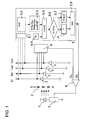
- a position measuring device with the control according to the invention is shown schematically.
- a light source is shown, which is formed in the illustrated embodiment as an LED 1.
- the LED 1 opposite is a material measure in the form of a transparent scale 2, are applied to the opaque division lines.
- the position measuring device on four photodetectors 3, wherein the scale 2 between the photodetectors 3 and the LED 1 is located.
- the photodetectors 3 are integrated in the example shown in a semiconductor element, in particular an ASIC.
- the scale 2 is displaceable relative to the LED 1 in the direction of the double arrow in FIGS. 1 and 2, the relative position between scale 2 and LED 1 being measured by the position measuring device.
- the light emitted by the LED 1 is modulated position-dependent by the scale 2 and converted in the photodetectors 3 in position-dependent photocurrents I 0 ° , I 90 ° , I 180 ° , I 270 ° .
- the position-dependent photocurrents I 0 ° , I 90 ° , I 180 ° , I 270 ° produced in this way ideally have a sinusoidal profile and have a phase offset of 90 ° in each case.
- the position-dependent photocurrents I 0 ° , I 90 ° , I 180 ° , I 270 ° are then further processed in a, not shown in the figures, evaluation, so that from them ultimately the position to be determined position data are generated.
- the invention is not limited to arrangements in which exactly four photodetectors 3 are used, or in which four photocurrents I 0 ° , I 90 ° , I 190 °, I 270 ° are evaluated.
- two or three photodetectors and correspondingly two or three position-dependent photocurrents can also be used for the evaluation.
- the average photocurrent which is formed from the sum of all position-dependent photocurrents I 0 ° , I 90 ° , I 180 ° , I 270 ° , is ideally constant. But if, for example, the intensity of the LED 1 decreases, the average photocurrent will also be reduced. In particular, if the scale 2 is contaminated, for example by a liquid film, it may be that the average of the position-dependent photocurrents I 0 ° , I 90 ° , I 180 ° , I 270 ° remains virtually unchanged from the ideal case, but the Degree of modulation of the position-dependent photocurrents I 0 ° , I 90 ° , I 180 ° , I 270 ° greatly reduced.
- a total voltage is according to FIG 1 with a sum generator 4 by an analogous procedure based on the position-dependent photocurrents formed at the same time as the actual value U 4 in Control circuit for controlling the intensity of the LED 1 is used.
- This actual variable U 4 is then supplied to a comparator, which is designed in the form of a differential amplifier 6, and used there as an actual value for the regulation of the LED 1.
- the required magnitude U 5 required for the regulation of the intensity of the LED 1 is determined by means of a means for generating a desired value U 5 , in the example shown with the aid of a circuit 5.
- the setpoint value U 5 can be seen as an electrical voltage.
- the circuit 5 is located on the same ASIC on which the photodetectors 3 are also arranged.
- These electrical signals in the form of the photo voltages U 0 ° , U 90 ° , U 180 ° , U 270 ° , which consequently on the position-dependent photocurrents I 0 ° , I 90 ° , I 180 ° , I 270 ° . are then digitized in an analog-to-digital converter 5.2, that is converted into digital values.
- an already stored value of a desired pointer length SL is read from a memory element, here an EPROM 5.4.
- the desired pointer length SL is already in the configuration of the position measuring device, ie before the actual measuring insert, permanently stored. The value of the desired pointer length SL is then no longer changed over the entire lifetime of the position measuring device.
- This new setpoint value Y ' is then converted in a digital-to-analogue converter 5.8 into an analogue nominal value U 5 (electrical voltage) which, as described above, is dependent on the position-dependent photocurrents I 0 ° , I 90 ° , I 180 ° , I 270 ° based.
- the so-called summation current method can be used in which the pointer length S based on the sum of the position-dependent photocurrents I 0 ° , I 90 ° , I 180 ° , I 270 ° determined becomes.
- the analog target size U 5 is then supplied to the differential amplifier 6, where it is compared with the actual size U 4 , so that a control difference for controlling the intensity of the LED 1 is generated.
- the control difference which also represents a voltage in physical terms, is applied to a steeping member, in the exemplary embodiment shown, to a transistor 7, in particular at the base of the transistor 7.
- the height or amplitude of the current that is fed into the LED 1 adjusts.
- the intensity of the light emitted by the LED 1 is known to be a function of the level of the current fed into the LED 1.
- a corresponding nominal value Y is set stored in the setpoint memory 5.7 over a certain time.
- the setpoint value Y will remain unchanged until the next time the position measuring device is switched on. This means that from this point until the next switch-on of the position measuring device, the circuit elements shown in dashed lines are no longer active.
- the setpoint value U 5 is checked in each case after the position measuring device is switched on and, if necessary, a corresponding value Y is stored after several iteration steps, so that the setpoint value U 5 until the next switch-on operation in the control loop for regulating the intensity of the LED 1 remains unchanged.
- the desired value Y can also be checked permanently during the operation of the position measuring device.
- a support point-dependent determination of the setpoint value Y at predetermined time intervals, for. B. every 68 microseconds are made, or else be position-dependent, z. B. the setpoint Y every 100 signal periods can be determined.
- control can also be configured so that when the comparator 5.6 detects a too large difference ⁇ between the actual pointer length S and the predetermined value of the setpoint pointer length SL during operation, only one alarm is triggered during operation. In the case of the alarm then the position measuring device is to be restarted, so that thus the renewed fixing or storing a changed Setpoint value Y in setpoint memory 5.7 is carried out with the startup procedure.
- the photodetectors 3, 8 are arranged such that light modulated by a part number of the photodetectors of the scale 2 is converted into position-dependent photocurrents I 0 ° , I 90 ° , I 180 ° , I 270 ° .
- the determination of the target size U 5 is therefore based only on photo currents I 0 ° , I 90 ° , I 180 , I 270 ° a part number of the photodetectors, namely the photodetectors 3.
- the target size U 5 with the same circuit 5 as determined in the first embodiment.
- the non-modulated light of the LED 1 is converted by a photodetector 8 into a photocurrent, this photocurrent representing the basis for the actual quantity U 8 . That is, for the regulation of the intensity of the LED 1, an actual quantity U 8 is used, which is ultimately generated by the photodetector 8, which receives light emitted by the LED 1 which is not position-modulated by the scale 2.
- the actual size U 8 is then supplied to the differential amplifier 6, as in the first embodiment, where a comparison between the actual size U 8 and the target size U 5 is performed, so that a control difference for controlling the intensity of the LED 1 is determined.
- the control difference is applied in the form of a voltage to the base of the transistor 7, so that the LED 1 is ultimately supplied with an electric current, the amount of which depends on the control difference.
- the desired value U 5 is determined in each case by a digital method.
- the invention also includes Arrangements and methods in which the target size U 5 is determined by an analog circuit.
Landscapes
- Physics & Mathematics (AREA)
- General Physics & Mathematics (AREA)
- Length Measuring Devices By Optical Means (AREA)
- Optical Transform (AREA)
- Formation Of Various Coating Films On Cathode Ray Tubes And Lamps (AREA)
Abstract
Description
Die Erfindung betrifft eine Vorrichtung zur Regelung einer Lichtquelle in einem Positionsmessgerät gemäß dem Oberbegriff des Anspruches 1 und ein entsprechendes Verfahren gemäß dem Anspruch 6.The invention relates to a device for controlling a light source in a position measuring device according to the preamble of claim 1 and a corresponding method according to
In Positionsmessgeräten werden häufig Lichtquellen eingesetzt, deren Licht positionsabhängig durch eine entsprechende Maßverkörperung zum Beispiel in Form eines Maßstabes oder einer Teilscheibe moduliert wird. Das modulierte Licht wird üblicherweise durch Fotodetektoren in elektrische Fotoströme umgewandelt, so dass die relative Position zwischen der Lichtquelle und der Maßverkörperung aus diesen positionsabhängigen Fotoströmen ermittelt werden kann.In position measuring devices, light sources are often used whose light is modulated position-dependent by a corresponding material measure, for example in the form of a scale or a slice. The modulated light is usually converted by photodetectors into electrical photocurrents, so that the relative position between the light source and the material measure from these position-dependent photocurrents can be determined.
Bei derartigen Positionsmessgeräten kommt es vor, dass sich die Lichtintensität mit der Zeit verändert, zum Beispiel dass sie durch Alterung der Lichtquelle im Laufe der Betriebszeit zurückgeht. Wegen den Änderungen der von den Fotodetektoren empfangenen Lichtintensität wird häufig zur Verbesserung der Messqualität eine Regelung der Lichtquelle vorgenommen.In such position measuring devices, it happens that the light intensity changes over time, for example, that it is due to aging of the light source in the course of the operating time. Because of the changes in the light intensity received by the photodetectors, control of the light source is often made to improve the quality of measurement.
In der
Der Erfindung liegt daher die Aufgabe zugrunde, eine Vorrichtung und ein Verfahren zu schaffen, durch das eine sichere, robuste, insbesondere gegenüber Verschmutzungen unempfindliche Positionsmessung mit hoher Genauigkeit möglich ist.The invention is therefore based on the object to provide an apparatus and a method by which a safe, robust, in particular insensitive to contamination position measurement with high accuracy is possible.
Diese Aufgabe wird erfindungsgemäß durch die Merkmale des Anspruches 1 bzw. des Anspruches 6 gelöst.This object is achieved by the features of claim 1 and of
Erfindungsgemäß wird die zur Regelung einer Lichtquelle maßgebliche Soll-Größe, basierend auf positionsabhängigen Fotoströmen erzeugt, wobei die positionsabhängigen Fotoströme durch Umwandlung von moduliertem Licht der Lichtquelle mittels Fotodetektoren entstehen. Die für die Bestimmung der Regeldifferenz zur Regelung der Lichtquelle weiterhin erforderliche Ist-Größe wird basierend auf positionsabhängigen oder auch auf positionsunabhängigen Fotoströmen gebildet.According to the invention, the setpoint quantity which is decisive for the regulation of a light source is generated based on position-dependent photocurrents, the position-dependent photocurrents being produced by conversion of modulated light of the light source by means of photodetectors. The actual size required for determining the control difference for controlling the light source is formed based on position-dependent or position-independent photo currents.
Mit Vorteil sind die Fotodetektoren und ein Mittel zur Erzeugung der Soll-Größe auf ein und demselben ASIC untergebracht.Advantageously, the photodetectors and a means for generating the desired size are accommodated on one and the same ASIC.
In einer bevorzugten Ausgestaltung der Erfindung werden zur Ermittlung der Soll-Größe zunächst mit einem Analog-Digitalwandler elektrische Signale digitalisiert, welche auf positionsabhängigen Fotoströmen basieren. Danach werden diese digitalen Werte weiterverarbeitet.In a preferred embodiment of the invention, electrical signals are first digitized with an analog-to-digital converter to determine the desired size, which are based on position-dependent photocurrents. Afterwards, these digital values are processed further.
Vorteilhafte Ausbildungen der Erfindung entnimmt man den abhängigen Ansprüchen.Advantageous embodiments of the invention will remove the dependent claims.
Weitere Einzelheiten und Vorteile des erfindungsgemäßen Verfahrens und der entsprechenden Vorrichtung zur Regelung einer Lichtquelle eines Positionsmessgerätes ergeben sich aus der nachfolgenden Beschreibung zweier Ausführungsbeispiele anhand der beiliegenden Figuren.Further details and advantages of the method according to the invention and the corresponding device for controlling a light source of a position measuring device will become apparent from the following description of two embodiments with reference to the accompanying figures.
Es zeigen die
- Figur 1
- eine schematische Darstellung eines ersten Ausführungsbeispieles der Erfindung,
Figur 2- eine schematische Darstellung eines zweiten Ausführungsbeispieles der Erfindung.
- FIG. 1
- a schematic representation of a first embodiment of the invention,
- FIG. 2
- a schematic representation of a second embodiment of the invention.
In der Beschreibung der Ausführungsbeispiele sind der Übersichtlichkeit halber gleichwirkende Bauteile mit gleichen Bezugszeichen versehen.In the description of the embodiments, for the sake of clarity equivalent components are provided with the same reference numerals.
In der Figur 1 ist schematisch der Aufbau eines Positionsmessgerätes mit der erfindungsgemäßen Regelung gezeigt. Dabei ist eine Lichtquelle dargestellt, die im vorgestellten Ausführungsbeispiel als eine LED 1 ausgebildet ist. Der LED 1 gegenüber befindet sich eine Maßverkörperung in Form eines transparenten Maßstabes 2, auf dem lichtundurchlässige Teilungsstriche aufgebracht sind. Darüber hinaus weist das Positionsmessgerät vier Fotodetektoren 3 auf, wobei sich der Maßstab 2 zwischen den Fotodetektoren 3 und der LED 1 befindet. Die Fotodetektoren 3 sind im gezeigten Beispiel in einem Halbleiterelement, insbesondere einem ASIC, integriert.In the figure 1, the construction of a position measuring device with the control according to the invention is shown schematically. In this case, a light source is shown, which is formed in the illustrated embodiment as an LED 1. The LED 1 opposite is a material measure in the form of a
Im vorgestellten Ausführungsbeispiel wird eine vergleichsweise einfache Ausgestaltung der optischen Elemente beschrieben. Es ist selbstverständlich, dass die Erfindung auch in Positionsmessgeräten mit wesentlich komplexeren optischen Anordnungen angewendet werden kann.In the presented embodiment, a comparatively simple embodiment of the optical elements is described. It goes without saying that the invention can also be used in position measuring devices with much more complex optical arrangements.
Der Maßstab 2 ist in Richtung des Doppelpfeils in den Figuren 1 und 2 relativ zur LED 1 verschiebbar, wobei durch das Positionsmessgerät die Relativposition zwischen Maßstab 2 und LED 1 gemessen wird. Zu diesem Zweck wird das von der LED 1 emittierte Licht durch den Maßstab 2 positionsabhängig moduliert und in den Fotodetektoren 3 in positionsabhängige Fotoströme I0°, I90°, I180°, I270° umgewandelt. Die auf diese Weise erzeugten positionsabhängigen Fotoströme I0°, I90°, I180°, I270° weisen idealerweise einen sinusförmigen Verlauf auf und haben einen Phasenversatz von jeweils 90°. Die positionsabhängigen Fotoströme I0°, I90°, I180°, I270° werden danach in einer, in den Figuren nicht dargestellten, Auswerteelektronik weiterverarbeitet, so dass aus ihnen letztlich die zu bestimmenden Positionsdaten erzeugt werden. Die Erfindung ist nicht auf Anordnungen eingeschränkt bei denen genau vier Fotodetektoren 3 eingesetzt werden, bzw. bei denen vier Fotoströme I0°, I90°, I190°, I270° ausgewertet werden. Es können hier beispielsweise auch zwei oder drei Fotodetektoren und entsprechend dann zwei oder drei positionsabhängige Fotoströme zur Auswertung herangezogen werden.The
Der mittlere Fotostrom, der aus der Summe aller positionsabhängigen Fotoströme I0°, I90°, I180°, I270° gebildet wird, ist im Idealfall konstant. Wenn aber beispielsweise die Intensität der LED 1 nachlässt, so wird sich auch der mittlere Fotostrom reduzieren. Insbesondere, wenn der Maßstab 2 verschmutzt ist, zum Beispiel durch einen Flüssigkeitsfilm, kann es jedoch sein, dass der Mittelwert der positionsabhängigen Fotoströme I0°, I90°, I180°, I270° gegenüber dem Idealfall nahezu unverändert bleibt, aber der Modulationsgrad der positionsabhängigen Fotoströme I0°, I90°, I180°, I270° stark reduziert ist. Das heißt, dass Bereiche, wo im Idealfall kaum Licht einfällt, die also dunkel sein sollten, zum Beispiel wegen Streuungseffekten nunmehr heller sind. Demgegenüber werden an sich helle Bereiche durch die Verschmutzung dunkler. Die Abweichungen in den Extrema der positionsabhängigen Fotoströme I0°, I90°, I180°, I270° vom mittleren Fotostrom wird also geringer bzw. der Modulationsgrad wird reduziert. Ein reduzierter Modulationsgrad führt zu schlechteren bzw. geringeren Messsignalamplituden. Gerade im Zusammenhang mit Verschmutzungen, die zu einer Reduktion des Modulationsgrades führen, weisen herkömmliche Positionsmessgeräte erhebliche Nachteile auf.The average photocurrent, which is formed from the sum of all position-dependent photocurrents I 0 ° , I 90 ° , I 180 ° , I 270 ° , is ideally constant. But if, for example, the intensity of the LED 1 decreases, the average photocurrent will also be reduced. In particular, if the
Im gezeigten ersten Ausführungsbeispiel wird gemäß der Figur 1 mit einem Summengenerator 4 durch ein analoges Verfahren auf Basis der positionsabhängigen Fotoströme I0°, I90°, I180°, I270° eine Summenspannung gebildet, die gleichzeitig als Ist-Größe U4 im Regelkreis zur Regelung der Intensität der LED 1 dient. Diese Ist-Größe U4 wird dann einem Vergleicher, der in Form eines Differenzverstärkers 6 ausgestaltet ist zugeführt, und dort als Istwert für die Regelung der LED 1 verwendet.In the first embodiment shown I 0 °, I 90 °, I 180 °, I 270 °, a total voltage is according to FIG 1 with a sum generator 4 by an analogous procedure based on the position-dependent photocurrents formed at the same time as the actual value U 4 in Control circuit for controlling the intensity of the LED 1 is used. This actual variable U 4 is then supplied to a comparator, which is designed in the form of a
Die für die Regelung der Intensität der LED 1 erforderliche Soll-Größe U5 wird mit Hilfe eines Mittels zur Erzeugung einer Soll-Größe U5, im gezeigten Beispiel mit Hilfe einer Schaltung 5, bestimmt. Physikalisch kann die Soll-Größe U5 als eine elektrische Spannung gesehen werden. Im gezeigten Beispiel befindet sich im Übrigen die Schaltung 5 auf dem selben ASIC, auf dem auch die Fotodetektoren 3 angeordnet sind.The required magnitude U 5 required for the regulation of the intensity of the LED 1 is determined by means of a means for generating a desired value U 5 , in the example shown with the aid of a
Die Funktionsweise der Schaltung 5 und deren Elemente werden im Folgenden erläutert. Zunächst werden nach dem Einschalten des Positionsmessgerätes die positionsabhängigen Fotoströme I0°, I90°, I180°, I270° in einem Strom-Spannungswandler 5.1 in Fotospannungen U0°, U90°, U180°, U270° umgewandelt. Diese elektrischen Signale in Form der Fotospannungen U0°, U90°, U180°, U270°, welche folglich auf den positionsabhängigen Fotoströmen I0°, I90°, I180°, I270°. basieren, werden dann in einem Analog-Digital-Wandler 5.2 digitalisiert, also in digitale Werte umgeformt. Aus diesen digitalen Werten, die den Fotospannungen U0°, U90°, U180°, U270° entsprechen, werden eine erste Differenz A = U0° - U180° und eine zweite Differenz B = U90° - U270° gebildet. Diese Differenzen A und B werden in einem Berechnungsmodul 5.3 quadriert und die entsprechende Summe der Quadrate bestimmt. Danach wird aus der Summe der Quadrate die Quadratwurzel ermittelt, so dass als Ergebnis dieser Transformation eine im Betrieb des Positionsmessgerätes tatsächlich vorliegenden Zeigerlänge ![]()
![]()
Im nächsten Schritt wird aus einem Speicherelement, hier ein EPROM 5.4, ein bereits abgespeicherter Wert einer Soll-Zeigerlänge SL ausgelesen. Im gezeigten Ausführungsbeispiel wird die Soll-Zeigerlänge SL bereits bei der Konfiguration des Positionsmessgerätes, also vor dem eigentlichen Messeinsatz, dauerhaft abgespeichert. Der Wert der Soll-Zeigerlänge SL wird dann über die gesamte Lebensdauer des Positionsmessgerätes nicht mehr verändert.In the next step, an already stored value of a desired pointer length SL is read from a memory element, here an EPROM 5.4. In the illustrated embodiment, the desired pointer length SL is already in the configuration of the position measuring device, ie before the actual measuring insert, permanently stored. The value of the desired pointer length SL is then no longer changed over the entire lifetime of the position measuring device.
Der vorgegebene Wert der Soll-Zeigerlänge SL wird daraufhin vom der tatsächlich vorliegenden Zeigerlänge S mit dem in einem Differenzbildner 5.5 subtrahiert, so dass die Differenz Δ = S -SL berechnet wird.The predetermined value of the desired pointer length SL is then subtracted from the actually present pointer length S with that in a subtractor 5.5, so that the difference Δ = S -SL is calculated.
In einem Vergleicher 5.6 wird danach überprüft, ob die Differenz Δ innerhalb vorgegebener Grenzen liegt oder nicht. Es wird also abgefragt, ob Δ größer ist als eine untere vorbestimmte Grenze LL und ob Δ kleiner ist als eine obere vorbestimmte Grenze LH. Im Allgemeinen wird hier im ersten Iterationsschritt eine unzulässig große Abweichung vorliegen, so dass zu einem Sollwert Y (im ersten Iterationsschritt ist hier ein Default-Wert vorgegeben) ein Wert Yi addiert oder subtrahiert wird, je nachdem ob der Wert Δ über oder unter den Grenzen LH bzw. LL liegt. Der neue Sollwert Y' = Y±Yi wird dann im Sollwertspeicher 5.7 abgelegt. Dieser neue Sollwert Y' wird dann in einem Digital-Analogwandler 5.8 in eine analoge Soll-Größe U5 (elektrische Spannung) umgewandelt, die wie oben beschrieben, auf den positionsabhängigen Fotoströmen I0°, I90°, I180°, I270° basiert.In a comparator 5.6 is then checked whether the difference Δ is within predetermined limits or not. It is therefore queried whether Δ is greater than a lower predetermined limit L L and whether Δ is smaller than an upper predetermined limit L H. In general, an inadmissibly large deviation will be present here in the first iteration step, so that a value Yi is added or subtracted to a desired value Y (in the first iteration step a value Yi is set here), depending on whether the value Δ is above or below the limits L H or L L is located. The new setpoint Y '= Y ± Yi is then stored in the setpoint memory 5.7. This new setpoint value Y 'is then converted in a digital-to-analogue converter 5.8 into an analogue nominal value U 5 (electrical voltage) which, as described above, is dependent on the position-dependent photocurrents I 0 ° , I 90 ° , I 180 ° , I 270 ° based.
Alternativ zu diesem Verfahren zur Bestimmung der tatsächlich vorliegenden Zeigerlänge S kann beispielsweise auch das sogenannte Summenstrom-Verfahren verwendet werden, bei dem die Zeigerlänge S auf Basis der Summe der positionsabhängigen Fotoströme I0°, I90°, I180°, I270° ermittelt wird.As an alternative to this method for determining the actual present pointer length S, for example, the so-called summation current method can be used in which the pointer length S based on the sum of the position-dependent photocurrents I 0 ° , I 90 ° , I 180 ° , I 270 ° determined becomes.
Die analoge Soll-Größe U5 wird danach dem Differenzverstärker 6 zugeführt, wo sie mit der Ist-Größe U4 verglichen wird, so dass eine Regeldifferenz zur Regelung der Intensität der LED 1 erzeugt wird. Die Regeldifferenz, die physikalisch betrachtet ebenfalls eine Spannung darstellt, liegt an einem Steilglied, im gezeigten Ausführungsbeispiel einem Transistor 7, insbesondere an der Basis des Transistors 7 an. Entsprechend dieser Regeldifferenz stellt sich die Höhe bzw. Amplitude des Stroms ein, der in die LED 1 eingespeist wird. Die Intensität des von der LED 1 emittierten Lichtes ist bekanntermaßen eine Funktion der Höhe des in die LED 1 eingespeisten Stromes.The analog target size U 5 is then supplied to the
Entsprechend der so vorgenommenen Änderung der Lichtintensität ändern sich nun auch die Amplituden der positionsabhängigen Fotoströme I0°, I90°, I180°, I270°. Dies führt dann wiederum zu einer Änderung des Wertes der tatsächlich vorliegenden Zeigerlänge S.The amplitudes of the position-dependent photocurrents I 0 ° , I 90 ° , I 180 ° , I 270 ° now change in accordance with the change in the light intensity thus made. This in turn leads to a change in the value of the actual pointer length S.
Sobald vom Vergleicher 5.6 nach dem Durchlauf von einem oder mehrerer Iterationsschritte festgestellt wird, dass im Differenzbilder 5. 5 die Differenz Δ zwischen der tatsächlich vorliegenden Zeigerlänge S und dem vorgegebenen Wert der Soll-Zeigerlänge SL innerhalb der vorgegebenen Grenzen liegt, wird ein entsprechender Sollwert Y im Sollwertspeicher 5.7 über eine bestimmte Zeit gespeichert. Im gezeigten Beispiel wird der Sollwert Y bis zum nächsten Einschalten des Positionsmessgerätes unverändert bleiben. Das heißt, dass ab diesem Zeitpunkt bis zum nächsten Einschaltvorgang des Positionsmessgerätes die gestrichelt dargestellten Schaltungselemente nicht mehr aktiv sind. Im vorgestellten Ausführungsbeispiel wird also jeweils nach dem Einschalten des Positionsmessgerätes die Soll-Größe U5 überprüft und ggf. nach mehreren Iterationsschritten ein entsprechender Wert Y abgespeichert, so dass der Soll-Größe U5 bis zum nächsten Einschaltvorgang im Regelkreis zur Regelung der Intensität der LED 1 unverändert bleibt.As soon as it is determined by the comparator 5.6 after the passage of one or more iteration steps that the difference Δ between the actual pointer length S and the predetermined value of the setpoint pointer length SL is within the predetermined limits, a corresponding nominal value Y is set stored in the setpoint memory 5.7 over a certain time. In the example shown, the setpoint value Y will remain unchanged until the next time the position measuring device is switched on. This means that from this point until the next switch-on of the position measuring device, the circuit elements shown in dashed lines are no longer active. Thus, in the exemplary embodiment shown, the setpoint value U 5 is checked in each case after the position measuring device is switched on and, if necessary, a corresponding value Y is stored after several iteration steps, so that the setpoint value U 5 until the next switch-on operation in the control loop for regulating the intensity of the LED 1 remains unchanged.
In einer Abwandlung der Erfindung kann der Sollwert Y aber auch permanent während des Betriebs des Positionsmessgerätes überprüft werden. Dabei kann eine stützpunktabhängige Ermittlung des Sollwerts Y in vorgegebenen Zeitintervallen, z. B. alle 68 µs vorgenommen werden, oder aber auch positionsabhängig erfolgen, z. B. kann der Sollwert Y alle 100 Signalperioden bestimmt werden.In a modification of the invention, the desired value Y can also be checked permanently during the operation of the position measuring device. In this case, a support point-dependent determination of the setpoint value Y at predetermined time intervals, for. B. every 68 microseconds are made, or else be position-dependent, z. B. the setpoint Y every 100 signal periods can be determined.
Die Regelung kann aber auch so konfiguriert sein, dass, wenn der Vergleicher 5.6 während des Betriebs eine zu große Differenz Δ zwischen der tatsächlich vorliegenden Zeigerlänge S und der vorgegebenen Wert der Soll-Zeigerlänge SL feststellt, während des Betriebes lediglich ein Alarm ausgelöst wird. Im Falle des Alarms ist dann das Positionsmessgerät neu zu starten, so dass somit die neuerliche Festsetzung bzw. Speicherung eines veränderten Sollwertes Y im Sollwertspeicher 5.7 mit der Startprozedur vorgenommen wird.However, the control can also be configured so that when the comparator 5.6 detects a too large difference Δ between the actual pointer length S and the predetermined value of the setpoint pointer length SL during operation, only one alarm is triggered during operation. In the case of the alarm then the position measuring device is to be restarted, so that thus the renewed fixing or storing a changed Setpoint value Y in setpoint memory 5.7 is carried out with the startup procedure.
In der Figur 2 ist eine alternative Ausgestaltung der Erfindung durch ein zweites Ausführungsbeispiel gezeigt. Dabei sind die Fotodetektoren 3;8 so angeordnet, dass durch eine Teilanzahl der Fotodetektoren vom Maßstab 2 moduliertes Licht in positionsabhängige Fotoströme I0°, I90°, I180°, I270° umgewandelt wird. Die Ermittlung der Soll-Größe U5 basiert also nur auf Fotoströmen I0°, I90°, I180, I270° einer Teilanzahl der Fotodetektoren, nämlich der Fotodetektoren 3. Im zweiten Ausführungsbeispiel wird ferner die Soll-Größe U5 mit der gleichen Schaltung 5 wie im ersten Ausführungsbeispiel ermittelt.2 shows an alternative embodiment of the invention is shown by a second embodiment. In this case, the
Der wesentliche Unterschied zum ersten Ausführungsbeispiel besteht nun darin, dass im zweiten Ausführungsbeispiel das nicht-modulierte Licht der LED 1 durch einen Fotodetektor 8 in einen Fotostrom umgewandelt wird, wobei dieser Fotostrom die Basis für die Ist-Größe U8 darstellt. Das heißt, dass für die Regelung der Intensität der LED 1 eine Ist-Größe U8 verwendet wird, die letztlich von dem Fotodetektor 8 erzeugt wird, welcher von der LED 1 emittiertes Licht empfängt, das nicht durch den Maßstab 2 positionsabhängig moduliert wird.The essential difference from the first exemplary embodiment is that in the second exemplary embodiment the non-modulated light of the LED 1 is converted by a photodetector 8 into a photocurrent, this photocurrent representing the basis for the actual quantity U 8 . That is, for the regulation of the intensity of the LED 1, an actual quantity U 8 is used, which is ultimately generated by the photodetector 8, which receives light emitted by the LED 1 which is not position-modulated by the
Die Ist-Größe U8 wird dann, wie auch im ersten Ausführungsbeispiel, dem Differenzverstärker 6 zugeführt, wo ein Vergleich zwischen der Ist-Größe U8 und der Soll-Größe U5 durchgeführt wird, so dass eine Regeldifferenz zur Regelung der Intensität der LED 1 ermittelt wird. Dabei wird auch hier die Regeldifferenz in Form einer Spannung an die Basis des Transistors 7 angelegt, so dass die LED 1 letztlich mit einem elektrischen Strom, dessen Höhe von der Regeldifferenz abhängt versorgt wird.The actual size U 8 is then supplied to the
Im zweiten Ausführungsbeispiel muss zur Ermittlung der Ist-Größe U8 keine Summenbildung von mehreren Fotoströmen vorgenommen werden, sondern es wird hier direkt der Gleichlichtanteil mit dem Fotodetektor 8 bestimmt.In the second exemplary embodiment, no summation of a plurality of photocurrents has to be undertaken to determine the actual size U 8 , but instead the direct light component with the photodetector 8 is determined directly here.
In den gezeigten Ausführungsbeispielen wird die Soll-Größe U5 jeweils durch ein digitales Verfahren bestimmt. Die Erfindung umfasst jedoch auch Anordnungen und Verfahren, bei denen die Soll-Größe U5 durch eine analoge Schaltung ermittelt wird.In the exemplary embodiments shown, the desired value U 5 is determined in each case by a digital method. However, the invention also includes Arrangements and methods in which the target size U 5 is determined by an analog circuit.
Claims (12)
- Device for controlling a light source (1) of a position measuring device, comprising- a material measure (2) which is displaceable relative to the light source (1),- a plurality of photodetectors (3; 8), by means of which the light emitted from the light source (1) can be converted into photocurrents (I0°, I90°, I180°, I270°; I8), the photocurrent (I0°, I90°, I180°, I270°; I8) at least of one of the photodetectors (3; 8) being able to be used as the basis for forming an actual variable (U4; U8), and
the photodetectors (3; 8) being disposed such that light modulated by the material measure (2) by at least a partial number of the photodetectors (3) can be converted into position-dependent photocurrents (I0°, I90°, I180°, I270°),- a means (5) for producing a reference variable (U5), and- a comparator (6), by means of which a comparison between the actual variable (U4; U8) and the reference variable (U5) can be implemented in order to produce a control difference for controlling the intensity of the light source (1),characterised in that the reference variable (U5) can be produced by the means (5), based on the position-dependent photocurrents (I0°, I90°, I180°, I270°). - Position measuring device according to claim 1, characterised in that the means (5) for producing the reference variable (U5) has a calculation module (5.3) for forming the vector length (S) of signals which are based on the position-dependent photocurrents (I0°, I90°, I180°, I270°).
- Position measuring device according to claim 1 or 2, characterised in that the means (5) for producing the reference variable (U5) has an analogue-digital converter (5.2) for digitalising signals which are based on the position-dependent photocurrents (I0°, I90°, I180°, I270°).
- Position measuring device according to claim 3, characterised in that the means (5) for producing the reference variable (U5) has a digital-analogue converter (5.8) for providing an analogue reference variable (U5).
- Position measuring device according to one of the preceding claims, characterised in that the photodetectors (3; 8) and the means (5) for producing the reference variable (U5) are integrated in a semiconductor element.
- Method for controlling a light source (1) of a position measuring device having the following steps:- conversion of light, which is determined from the light source (1), by means of photodetectors (3; 8) into photocurrents (I0°, I90°, I180°, I270°, I8), at least a part of the emitted light being modulated by a material measure (2) which can be displaced relative to the light source (1) so that position-dependent photocurrents (I0°, I90°, I180°, I270°) are produced by the modulated light by means of at least a partial number of the photodetectors (3),- production of an actual variable (U4; U8), based on at least one of the photocurrents (I0°, I90°, I180°, I270°, I8),- production of a reference variable (U5), based on the position-dependent photocurrents (I0°, I90°, I180°, I270°) and- comparison of the actual variable (U4; U8) with the reference variable (U5) for producing a control difference for controlling the intensity of the light source (1).
- Method according to claim 6, the actual variable (U4; U8) being produced by an analogue method.
- Method according to claim 6 or 7, the actual variable (U4) being produced on the basis of the sum of the photocurrents (I0°, I90°, I180°, I270°, I8).
- Method according to one of the claims 6 to 8, electrical signals which are based on the position-dependent photocurrents (I0°, I90°, I180°, I270°) being digitalised for producing the reference variable (U5).
- Method according to one of the claims 6 to 9, the vector length (S) of electrical signals which are based on the position-dependent photocurrents (I0°, I90°, I180°, I270°) being formed for producing the reference variable (U5).
- Method according to claim 10, the vector length (S) being compared with a prescribed value of a reference vector length (SL) and the reference variable (U5) being changed until the difference (Δ) between the vector length (S) and the reference vector length (SL) is within prescribed limits.
- Method according to one of the claims 9 to 11, a digital-analogue conversion being undertaken after the digitalisation and after the further processing of the digitalised values for providing the reference variable (U5).
Applications Claiming Priority (2)
| Application Number | Priority Date | Filing Date | Title |
|---|---|---|---|
| DE10339366 | 2003-08-27 | ||
| DE10339366A DE10339366A1 (en) | 2003-08-27 | 2003-08-27 | Method and device for controlling a light source of a position measuring device |
Publications (2)
| Publication Number | Publication Date |
|---|---|
| EP1510790A1 EP1510790A1 (en) | 2005-03-02 |
| EP1510790B1 true EP1510790B1 (en) | 2007-08-22 |
Family
ID=34089208
Family Applications (1)
| Application Number | Title | Priority Date | Filing Date |
|---|---|---|---|
| EP04011338A Expired - Lifetime EP1510790B1 (en) | 2003-08-27 | 2004-05-13 | Method and device for regulating the light source in a positioning measuring device |
Country Status (7)
| Country | Link |
|---|---|
| US (1) | US7235776B2 (en) |
| EP (1) | EP1510790B1 (en) |
| JP (1) | JP4473054B2 (en) |
| CN (1) | CN100408978C (en) |
| AT (1) | ATE371169T1 (en) |
| DE (2) | DE10339366A1 (en) |
| ES (1) | ES2293118T3 (en) |
Cited By (1)
| Publication number | Priority date | Publication date | Assignee | Title |
|---|---|---|---|---|
| DE102008008584A1 (en) | 2008-02-12 | 2009-08-13 | Bayerische Motoren Werke Aktiengesellschaft | Sliding bearing shell for split sliding bearing in internal combustion engine, has radially revolving processing cavities on inner surface, and lubricant slot running on side of shell and not before bevel of inner surface |
Families Citing this family (5)
| Publication number | Priority date | Publication date | Assignee | Title |
|---|---|---|---|---|
| JP2005291734A (en) * | 2004-03-31 | 2005-10-20 | Univ Nagoya | Measuring apparatus for light environment in forest |
| US8772705B2 (en) * | 2010-12-01 | 2014-07-08 | Avago Technologies General Ip (Singapore) Pte. Ltd. | Interpolation circuitry for optical encoders |
| DE102012108815A1 (en) | 2012-09-19 | 2014-03-20 | Ic-Haus Gmbh | Method for setting operating point of circuit arrangement of position measuring device, involves sampling material measure by sensor, where actual value is determined by sensor, over which correcting variable is controlled |
| CN103148779B (en) * | 2013-01-30 | 2016-01-13 | 中国科学院长春光学精密机械与物理研究所 | The adjusting gear of light source in position measurement apparatus |
| DE102013222383A1 (en) | 2013-02-06 | 2014-08-07 | Dr. Johannes Heidenhain Gmbh | Optical position measuring device |
Family Cites Families (13)
| Publication number | Priority date | Publication date | Assignee | Title |
|---|---|---|---|---|
| DE2730056A1 (en) * | 1977-07-02 | 1979-01-18 | Int Standard Electric Corp | Light emitter with laser diode control - uses detector output signal and has circuit providing output and bias control signals for diode |
| GB2054135B (en) | 1979-07-19 | 1984-03-14 | Burroughs Corp | Photo-electric displacement transducer |
| US4593194A (en) * | 1983-10-05 | 1986-06-03 | Quantum Corporation | Optical encoder with digital gain compensation controlling source intensity |
| US5015836A (en) * | 1990-02-05 | 1991-05-14 | Bei Electronics, Inc. | Source intensity adjustment apparatus for optical channel |
| JPH05256665A (en) | 1992-03-13 | 1993-10-05 | Canon Inc | Encoder |
| JP3312045B2 (en) * | 1992-09-25 | 2002-08-05 | オリンパス光学工業株式会社 | Eyepiece with viewfinder optical system |
| JP3170902B2 (en) * | 1992-09-30 | 2001-05-28 | キヤノン株式会社 | Signal processing method and encoder using the same |
| JPH0783612A (en) | 1993-09-17 | 1995-03-28 | Canon Inc | Optical type displacement sensor |
| US6492637B1 (en) * | 1999-05-10 | 2002-12-10 | Citizen Watch Co., Ltd. | Dimension measuring device |
| US6344641B1 (en) * | 1999-08-11 | 2002-02-05 | Agilent Technologies, Inc. | System and method for on-chip calibration of illumination sources for an integrated circuit display |
| JP2001311630A (en) | 2000-02-22 | 2001-11-09 | Mitsutoyo Corp | Optical encoder |
| US6380352B1 (en) * | 2000-08-29 | 2002-04-30 | Eastman Chemical Company | Polyester precursor purification process |
| US20030234351A1 (en) * | 2002-06-25 | 2003-12-25 | Chong-Hin Chee | Brightness independent optical position sensor |
-
2003
- 2003-08-27 DE DE10339366A patent/DE10339366A1/en not_active Withdrawn
-
2004
- 2004-05-13 EP EP04011338A patent/EP1510790B1/en not_active Expired - Lifetime
- 2004-05-13 ES ES04011338T patent/ES2293118T3/en not_active Expired - Lifetime
- 2004-05-13 AT AT04011338T patent/ATE371169T1/en not_active IP Right Cessation
- 2004-05-13 DE DE502004004708T patent/DE502004004708D1/en not_active Expired - Lifetime
- 2004-06-24 JP JP2004186662A patent/JP4473054B2/en not_active Expired - Fee Related
- 2004-08-27 CN CNB2004100682651A patent/CN100408978C/en not_active Expired - Fee Related
- 2004-08-27 US US10/927,689 patent/US7235776B2/en not_active Expired - Fee Related
Cited By (1)
| Publication number | Priority date | Publication date | Assignee | Title |
|---|---|---|---|---|
| DE102008008584A1 (en) | 2008-02-12 | 2009-08-13 | Bayerische Motoren Werke Aktiengesellschaft | Sliding bearing shell for split sliding bearing in internal combustion engine, has radially revolving processing cavities on inner surface, and lubricant slot running on side of shell and not before bevel of inner surface |
Also Published As
| Publication number | Publication date |
|---|---|
| US7235776B2 (en) | 2007-06-26 |
| EP1510790A1 (en) | 2005-03-02 |
| CN100408978C (en) | 2008-08-06 |
| US20050052641A1 (en) | 2005-03-10 |
| JP2005070032A (en) | 2005-03-17 |
| JP4473054B2 (en) | 2010-06-02 |
| DE10339366A1 (en) | 2005-03-24 |
| ATE371169T1 (en) | 2007-09-15 |
| ES2293118T3 (en) | 2008-03-16 |
| DE502004004708D1 (en) | 2007-10-04 |
| CN1590968A (en) | 2005-03-09 |
Similar Documents
| Publication | Publication Date | Title |
|---|---|---|
| DE102005056774B4 (en) | TOF pixel and method of operation | |
| EP2659232B1 (en) | Method and apparatus for determining a recognition threshold | |
| EP3888247A1 (en) | Analogue-to-digital converter | |
| DE2814265B2 (en) | Device for automatic adjustment of the setting of a microscope | |
| DE102008014411A1 (en) | Signal processing for an optical encoder | |
| EP1510790B1 (en) | Method and device for regulating the light source in a positioning measuring device | |
| EP0204897B1 (en) | Method and device for controlling the mark-to-space ratio of an electric signal | |
| DE4332254C1 (en) | Using a spacing sensor (separation sensor) for computer tomographs | |
| EP1207372B1 (en) | Method and device for conditioning a periodic analog signal | |
| EP2197117B1 (en) | Switching unit for creating an output voltage depending on a digital data value and method for calibrating the switching unit | |
| DE102011114953B4 (en) | Origin detection circuit | |
| EP0237583A1 (en) | Method and circuit arrangement to convert a measured voltage into a digital value | |
| DE2327802C3 (en) | Controllable analog amplifier for a photoelectric converter | |
| EP0446418B1 (en) | Level indicator | |
| DE2755038B2 (en) | Analog comparator | |
| CH669254A5 (en) | DEVICE FOR MEASURING AND ADJUSTING LENGTHS AND USING THE DEVICE. | |
| WO2014095474A1 (en) | Field device with an analogue output | |
| EP1093224A2 (en) | Pulse detector and method for the detection of sinusoidal pulses | |
| EP1378063B1 (en) | Method and circuit for linearising non-linear curves | |
| EP0456168A2 (en) | Device for the analogue-digital conversion of a measured quantity, generated by transducers disposed in a bridge circuit, in particular by gauges in a weighing cell | |
| DE69822029T2 (en) | Method for centering a signal within the dynamic range of a tip-detecting proximity sensor | |
| DE19708469C2 (en) | Procedure for calibration of an engraving system and engraving procedure | |
| DE2404933A1 (en) | REGULATORY ARRANGEMENT FOR SCANNING WITH THE AID OF A LIGHT POINT SCANNING TUBE | |
| EP0302002A1 (en) | Method for converting an analogue input signal into a digital output signal | |
| DE2633565A1 (en) | METHOD AND DEVICE FOR CONTACTLESS SPEED MEASUREMENT |
Legal Events
| Date | Code | Title | Description |
|---|---|---|---|
| PUAI | Public reference made under article 153(3) epc to a published international application that has entered the european phase |
Free format text: ORIGINAL CODE: 0009012 |
|
| AK | Designated contracting states |
Kind code of ref document: A1 Designated state(s): AT BE BG CH CY CZ DE DK EE ES FI FR GB GR HU IE IT LI LU MC NL PL PT RO SE SI SK TR |
|
| AX | Request for extension of the european patent |
Extension state: AL HR LT LV MK |
|
| 17P | Request for examination filed |
Effective date: 20050902 |
|
| AKX | Designation fees paid |
Designated state(s): AT BE BG CH CY CZ DE DK EE ES FI FR GB GR HU IE IT LI LU MC NL PL PT RO SE SI SK TR |
|
| GRAP | Despatch of communication of intention to grant a patent |
Free format text: ORIGINAL CODE: EPIDOSNIGR1 |
|
| GRAS | Grant fee paid |
Free format text: ORIGINAL CODE: EPIDOSNIGR3 |
|
| GRAA | (expected) grant |
Free format text: ORIGINAL CODE: 0009210 |
|
| AK | Designated contracting states |
Kind code of ref document: B1 Designated state(s): AT BE BG CH CY CZ DE DK EE ES FI FR GB GR HU IE IT LI LU MC NL PL PT RO SE SI SK TR |
|
| REG | Reference to a national code |
Ref country code: GB Ref legal event code: FG4D Free format text: NOT ENGLISH |
|
| GBT | Gb: translation of ep patent filed (gb section 77(6)(a)/1977) |
Effective date: 20070822 |
|
| REG | Reference to a national code |
Ref country code: CH Ref legal event code: EP |
|
| REG | Reference to a national code |
Ref country code: IE Ref legal event code: FG4D Free format text: LANGUAGE OF EP DOCUMENT: GERMAN |
|
| REG | Reference to a national code |
Ref country code: CH Ref legal event code: NV Representative=s name: TROESCH SCHEIDEGGER WERNER AG |
|
| REF | Corresponds to: |
Ref document number: 502004004708 Country of ref document: DE Date of ref document: 20071004 Kind code of ref document: P |
|
| PG25 | Lapsed in a contracting state [announced via postgrant information from national office to epo] |
Ref country code: BG Free format text: LAPSE BECAUSE OF FAILURE TO SUBMIT A TRANSLATION OF THE DESCRIPTION OR TO PAY THE FEE WITHIN THE PRESCRIBED TIME-LIMIT Effective date: 20071122 Ref country code: FI Free format text: LAPSE BECAUSE OF FAILURE TO SUBMIT A TRANSLATION OF THE DESCRIPTION OR TO PAY THE FEE WITHIN THE PRESCRIBED TIME-LIMIT Effective date: 20070822 Ref country code: NL Free format text: LAPSE BECAUSE OF FAILURE TO SUBMIT A TRANSLATION OF THE DESCRIPTION OR TO PAY THE FEE WITHIN THE PRESCRIBED TIME-LIMIT Effective date: 20070822 |
|
| NLV1 | Nl: lapsed or annulled due to failure to fulfill the requirements of art. 29p and 29m of the patents act | ||
| PG25 | Lapsed in a contracting state [announced via postgrant information from national office to epo] |
Ref country code: PL Free format text: LAPSE BECAUSE OF FAILURE TO SUBMIT A TRANSLATION OF THE DESCRIPTION OR TO PAY THE FEE WITHIN THE PRESCRIBED TIME-LIMIT Effective date: 20070822 |
|
| REG | Reference to a national code |
Ref country code: ES Ref legal event code: FG2A Ref document number: 2293118 Country of ref document: ES Kind code of ref document: T3 |
|
| REG | Reference to a national code |
Ref country code: IE Ref legal event code: FD4D |
|
| EN | Fr: translation not filed | ||
| PG25 | Lapsed in a contracting state [announced via postgrant information from national office to epo] |
Ref country code: GR Free format text: LAPSE BECAUSE OF FAILURE TO SUBMIT A TRANSLATION OF THE DESCRIPTION OR TO PAY THE FEE WITHIN THE PRESCRIBED TIME-LIMIT Effective date: 20071123 Ref country code: DK Free format text: LAPSE BECAUSE OF FAILURE TO SUBMIT A TRANSLATION OF THE DESCRIPTION OR TO PAY THE FEE WITHIN THE PRESCRIBED TIME-LIMIT Effective date: 20070822 |
|
| PG25 | Lapsed in a contracting state [announced via postgrant information from national office to epo] |
Ref country code: SK Free format text: LAPSE BECAUSE OF FAILURE TO SUBMIT A TRANSLATION OF THE DESCRIPTION OR TO PAY THE FEE WITHIN THE PRESCRIBED TIME-LIMIT Effective date: 20070822 Ref country code: IE Free format text: LAPSE BECAUSE OF FAILURE TO SUBMIT A TRANSLATION OF THE DESCRIPTION OR TO PAY THE FEE WITHIN THE PRESCRIBED TIME-LIMIT Effective date: 20070822 Ref country code: PT Free format text: LAPSE BECAUSE OF FAILURE TO SUBMIT A TRANSLATION OF THE DESCRIPTION OR TO PAY THE FEE WITHIN THE PRESCRIBED TIME-LIMIT Effective date: 20080122 |
|
| PLBE | No opposition filed within time limit |
Free format text: ORIGINAL CODE: 0009261 |
|
| STAA | Information on the status of an ep patent application or granted ep patent |
Free format text: STATUS: NO OPPOSITION FILED WITHIN TIME LIMIT |
|
| PG25 | Lapsed in a contracting state [announced via postgrant information from national office to epo] |
Ref country code: SE Free format text: LAPSE BECAUSE OF FAILURE TO SUBMIT A TRANSLATION OF THE DESCRIPTION OR TO PAY THE FEE WITHIN THE PRESCRIBED TIME-LIMIT Effective date: 20071122 Ref country code: RO Free format text: LAPSE BECAUSE OF FAILURE TO SUBMIT A TRANSLATION OF THE DESCRIPTION OR TO PAY THE FEE WITHIN THE PRESCRIBED TIME-LIMIT Effective date: 20070822 |
|
| 26N | No opposition filed |
Effective date: 20080526 |
|
| BERE | Be: lapsed |
Owner name: DR. JOHANNES HEIDENHAIN G.M.B.H. Effective date: 20080531 |
|
| PG25 | Lapsed in a contracting state [announced via postgrant information from national office to epo] |
Ref country code: MC Free format text: LAPSE BECAUSE OF NON-PAYMENT OF DUE FEES Effective date: 20080531 |
|
| PG25 | Lapsed in a contracting state [announced via postgrant information from national office to epo] |
Ref country code: EE Free format text: LAPSE BECAUSE OF FAILURE TO SUBMIT A TRANSLATION OF THE DESCRIPTION OR TO PAY THE FEE WITHIN THE PRESCRIBED TIME-LIMIT Effective date: 20070822 |
|
| PG25 | Lapsed in a contracting state [announced via postgrant information from national office to epo] |
Ref country code: BE Free format text: LAPSE BECAUSE OF NON-PAYMENT OF DUE FEES Effective date: 20080531 |
|
| PG25 | Lapsed in a contracting state [announced via postgrant information from national office to epo] |
Ref country code: SI Free format text: LAPSE BECAUSE OF FAILURE TO SUBMIT A TRANSLATION OF THE DESCRIPTION OR TO PAY THE FEE WITHIN THE PRESCRIBED TIME-LIMIT Effective date: 20070822 |
|
| PG25 | Lapsed in a contracting state [announced via postgrant information from national office to epo] |
Ref country code: CY Free format text: LAPSE BECAUSE OF FAILURE TO SUBMIT A TRANSLATION OF THE DESCRIPTION OR TO PAY THE FEE WITHIN THE PRESCRIBED TIME-LIMIT Effective date: 20070822 |
|
| PG25 | Lapsed in a contracting state [announced via postgrant information from national office to epo] |
Ref country code: AT Free format text: LAPSE BECAUSE OF NON-PAYMENT OF DUE FEES Effective date: 20080513 |
|
| PG25 | Lapsed in a contracting state [announced via postgrant information from national office to epo] |
Ref country code: LU Free format text: LAPSE BECAUSE OF NON-PAYMENT OF DUE FEES Effective date: 20080513 Ref country code: HU Free format text: LAPSE BECAUSE OF FAILURE TO SUBMIT A TRANSLATION OF THE DESCRIPTION OR TO PAY THE FEE WITHIN THE PRESCRIBED TIME-LIMIT Effective date: 20080223 |
|
| PG25 | Lapsed in a contracting state [announced via postgrant information from national office to epo] |
Ref country code: TR Free format text: LAPSE BECAUSE OF FAILURE TO SUBMIT A TRANSLATION OF THE DESCRIPTION OR TO PAY THE FEE WITHIN THE PRESCRIBED TIME-LIMIT Effective date: 20070822 |
|
| PG25 | Lapsed in a contracting state [announced via postgrant information from national office to epo] |
Ref country code: FR Free format text: LAPSE BECAUSE OF FAILURE TO SUBMIT A TRANSLATION OF THE DESCRIPTION OR TO PAY THE FEE WITHIN THE PRESCRIBED TIME-LIMIT Effective date: 20080418 |
|
| PGFP | Annual fee paid to national office [announced via postgrant information from national office to epo] |
Ref country code: CZ Payment date: 20140509 Year of fee payment: 11 |
|
| PG25 | Lapsed in a contracting state [announced via postgrant information from national office to epo] |
Ref country code: CZ Free format text: LAPSE BECAUSE OF NON-PAYMENT OF DUE FEES Effective date: 20150513 |
|
| PGFP | Annual fee paid to national office [announced via postgrant information from national office to epo] |
Ref country code: CH Payment date: 20180523 Year of fee payment: 15 Ref country code: ES Payment date: 20180625 Year of fee payment: 15 |
|
| PGFP | Annual fee paid to national office [announced via postgrant information from national office to epo] |
Ref country code: IT Payment date: 20180530 Year of fee payment: 15 |
|
| PGFP | Annual fee paid to national office [announced via postgrant information from national office to epo] |
Ref country code: GB Payment date: 20180518 Year of fee payment: 15 |
|
| PGFP | Annual fee paid to national office [announced via postgrant information from national office to epo] |
Ref country code: DE Payment date: 20190521 Year of fee payment: 16 |
|
| REG | Reference to a national code |
Ref country code: CH Ref legal event code: PL |
|
| GBPC | Gb: european patent ceased through non-payment of renewal fee |
Effective date: 20190513 |
|
| PG25 | Lapsed in a contracting state [announced via postgrant information from national office to epo] |
Ref country code: CH Free format text: LAPSE BECAUSE OF NON-PAYMENT OF DUE FEES Effective date: 20190531 Ref country code: LI Free format text: LAPSE BECAUSE OF NON-PAYMENT OF DUE FEES Effective date: 20190531 |
|
| PG25 | Lapsed in a contracting state [announced via postgrant information from national office to epo] |
Ref country code: GB Free format text: LAPSE BECAUSE OF NON-PAYMENT OF DUE FEES Effective date: 20190513 Ref country code: IT Free format text: LAPSE BECAUSE OF NON-PAYMENT OF DUE FEES Effective date: 20190513 |
|
| REG | Reference to a national code |
Ref country code: ES Ref legal event code: FD2A Effective date: 20200928 |
|
| PG25 | Lapsed in a contracting state [announced via postgrant information from national office to epo] |
Ref country code: ES Free format text: LAPSE BECAUSE OF NON-PAYMENT OF DUE FEES Effective date: 20190514 |
|
| REG | Reference to a national code |
Ref country code: DE Ref legal event code: R119 Ref document number: 502004004708 Country of ref document: DE |
|
| PG25 | Lapsed in a contracting state [announced via postgrant information from national office to epo] |
Ref country code: DE Free format text: LAPSE BECAUSE OF NON-PAYMENT OF DUE FEES Effective date: 20201201 |