JP2005291734A - Forest light environment measurement device - Google Patents
Forest light environment measurement device Download PDFInfo
- Publication number
- JP2005291734A JP2005291734A JP2004102832A JP2004102832A JP2005291734A JP 2005291734 A JP2005291734 A JP 2005291734A JP 2004102832 A JP2004102832 A JP 2004102832A JP 2004102832 A JP2004102832 A JP 2004102832A JP 2005291734 A JP2005291734 A JP 2005291734A
- Authority
- JP
- Japan
- Prior art keywords
- unicycle
- digital camera
- moving
- sensor
- wheel
- Prior art date
- Legal status (The legal status is an assumption and is not a legal conclusion. Google has not performed a legal analysis and makes no representation as to the accuracy of the status listed.)
- Pending
Links
Images
Classifications
-
- G—PHYSICS
- G01—MEASURING; TESTING
- G01J—MEASUREMENT OF INTENSITY, VELOCITY, SPECTRAL CONTENT, POLARISATION, PHASE OR PULSE CHARACTERISTICS OF INFRARED, VISIBLE OR ULTRAVIOLET LIGHT; COLORIMETRY; RADIATION PYROMETRY
- G01J1/00—Photometry, e.g. photographic exposure meter
- G01J1/42—Photometry, e.g. photographic exposure meter using electric radiation detectors
-
- G—PHYSICS
- G01—MEASURING; TESTING
- G01B—MEASURING LENGTH, THICKNESS OR SIMILAR LINEAR DIMENSIONS; MEASURING ANGLES; MEASURING AREAS; MEASURING IRREGULARITIES OF SURFACES OR CONTOURS
- G01B3/00—Measuring instruments characterised by the use of mechanical techniques
- G01B3/12—Measuring wheels
Landscapes
- Physics & Mathematics (AREA)
- General Physics & Mathematics (AREA)
- Spectroscopy & Molecular Physics (AREA)
- Studio Devices (AREA)
- Photometry And Measurement Of Optical Pulse Characteristics (AREA)
Abstract
【課題】GPSの利用できない森林内においても天頂角別光環境の空間分布を容易に測定できるようにすることにある。
【解決手段】光環境の測定用の測定機器と、前記測定機器を搭載し、一つの車輪で接地して走行する移動用一輪車4とを具え、前記測定機器は、超広角レンズ5aを装着され、その超広角レンズ5aを上方へ向けられたデジタルカメラ5と、デジタルカメラ5が撮影して出力した光データをそのデジタルカメラの位置および撮影方向と併せて記録する光データ記録装置7と、を有し、移動用一輪車4は、その一輪車の加速度および回転角をそれぞれ検出する加速度センサ9および回転角センサ10からの自律航法用情報と、車輪回転センサ8からの移動距離情報とに基づき、デジタルカメラ5による撮影の際のそのデジタルカメラ5の位置および撮影方向を求めて光データ記録装置7に与える測定位置・方向演算装置7を有することを特徴とする、移動式光環境測定装置である。
【選択図】図1An object of the present invention is to make it possible to easily measure the spatial distribution of light environments according to zenith angles even in forests where GPS cannot be used.
SOLUTION: A measuring device for measuring an optical environment and a moving unicycle 4 that is mounted with the measuring device and travels in contact with a single wheel, the measuring device is equipped with an ultra-wide angle lens 5a. A digital camera 5 with the super-wide-angle lens 5a facing upward, and an optical data recording device 7 that records the optical data photographed and output by the digital camera 5 together with the position and photographing direction of the digital camera. The moving unicycle 4 is digitally based on the autonomous navigation information from the acceleration sensor 9 and the rotation angle sensor 10 that detect the acceleration and the rotation angle of the unicycle, and the movement distance information from the wheel rotation sensor 8, respectively. It has a measurement position / direction arithmetic unit 7 which obtains the position and shooting direction of the digital camera 5 when shooting with the camera 5 and gives it to the optical data recording device 7. An expression optical measurement system.
[Selection] Figure 1
Description
この発明は、時空間的な変動の大きい森林内の光環境を迅速に測定するための光環境測定装置に関するものである。 The present invention relates to an optical environment measuring device for quickly measuring an optical environment in a forest having large temporal and spatial fluctuations.
森林内の光環境測定は,森林のバイオマスや葉量などの指標として活用されるばかりでなく、森林内の様々な生物の生育環境の研究にも重要である。近年の森林の二酸化炭素貯蓄量・光合成能力への関心の広がりや種の多様性の重要性の高まりに伴い、光環境測定装置に対する需要は増加しつつある。また光環境測定値を人工林の適切な管理のための指標値として利用することも期待されている。 Measurement of light environment in forests is not only used as an indicator of forest biomass and leaf quantity, but is also important for studying the growth environment of various organisms in forests. With the growing interest in carbon dioxide storage and photosynthetic capacity of forests and the importance of species diversity in recent years, the demand for light environment measuring devices is increasing. It is also expected that the measured light environment will be used as an index value for the appropriate management of planted forests.
ところで、森林の状態を簡便に調査する方法としては、天頂角別の光環境情報が有効であるが、森林内の光環境は、直達光、散乱光、反射光が時空間的な変動を伴って混在しているため、この把握には光センサの位置および方向を同定した迅速な多地点反復観測が求められる。 By the way, the light environment information for each zenith angle is effective as a simple method for investigating the state of the forest, but the direct light, scattered light, and reflected light are subject to temporal and spatial fluctuations in the light environment in the forest. In order to grasp this, rapid multi-point repeated observation that identifies the position and direction of the optical sensor is required.
しかしながら、一般に森林内はGPS(Global Positioning System)を利用できず、複雑な地形上の不均一な森林において位置を同定しながら迅速に天頂角別光環境を測定することは従来は困難であった。 However, in general, GPS (Global Positioning System) cannot be used in the forest, and it has been difficult in the past to quickly measure the light environment according to the zenith angle while identifying the position in a heterogeneous forest on complex terrain. .
この発明は、上記課題を有利に解決することを目的とするものであり、この発明の森林内光環境測定装置は、光環境の測定用の測定機器と、前記測定機器を搭載し、一つの車輪で走行面に接して走行する移動用一輪車と、を具え、前記測定機器は、超広角レンズを装着され、その超広角レンズを上方へ向けられたデジタルカメラと、前記デジタルカメラが撮影して出力した光データを前記デジタルカメラの位置および撮影方向と併せて記録する光データ記録装置と、を有し、前記移動用一輪車は、互いに直角な三軸周りの前記移動用一輪車の回転角を検出する回転角センサと、前記車輪の回転を検出する車輪回転センサと、前記回転角センサからの自律航法用情報と、前記車輪回転センサからの移動距離情報とに基づき、前記デジタルカメラによる撮影の際のそのデジタルカメラの位置および撮影方向を求めて前記光データ記録装置に与える測定位置・方向演算装置と、を有することを特徴とするものである。 An object of the present invention is to advantageously solve the above-described problems. An in-forest light environment measuring apparatus according to the present invention includes a measuring device for measuring a light environment and the measuring device, A moving unicycle that travels in contact with the traveling surface with wheels, and the measuring device is equipped with a super-wide-angle lens, the digital camera with the super-wide-angle lens facing upward, and the digital camera An optical data recording device that records the output optical data together with the position and shooting direction of the digital camera, and the unicycle for movement detects a rotation angle of the unicycle for movement around three axes perpendicular to each other. The digital camera based on the rotation angle sensor, the wheel rotation sensor that detects the rotation of the wheel, the autonomous navigation information from the rotation angle sensor, and the movement distance information from the wheel rotation sensor. It is characterized in that it has a measurement position and direction calculating device for providing the optical data recording device seeking the position and imaging direction of the digital camera at the time of shooting with.
かかる森林内光環境測定装置にあっては、測定機器を搭載した移動用一輪車が、測定作業者による手押しあるいは搭載モータ等の動力源で駆動されて、一つの車輪で地表面や路面や床面等の走行面に接して、森林内の道なき斜面や悪路、登山路等の走行面上を走行し、その走行中、回転角センサが、例えばその移動用一輪車の前後、左右および上下方向に延在する互いに直角な三軸周りのその移動用一輪車の回転角を検出し、車輪回転センサが、その移動用一輪車の車輪の回転を検出し、測定位置・方向演算装置が、上記回転角センサからの自律航法用情報と、上記車輪回転センサからの移動距離情報とに基づき、その移動用一輪車が搭載した測定機器のデジタルカメラによる撮影の際のそのデジタルカメラの位置および撮影方向を求めて光データ記録装置に与える。 In such an in-forest light environment measuring device, a moving unicycle equipped with a measuring device is driven by a power source such as a manual push by a measurement operator or a mounted motor, and the ground surface, road surface or floor surface is driven by one wheel. Travels on a road surface such as roadside slopes, bad roads, mountain trails, etc. in the forest, during which the rotation angle sensor, for example, the front, back, left, right, up and down direction of the unicycle for movement The rotation angle of the moving unicycle around three axes perpendicular to each other extending to the wheel is detected, the wheel rotation sensor detects the rotation of the wheel of the moving unicycle, and the measurement position / direction computing device is the rotation angle described above. Based on the information for autonomous navigation from the sensor and the movement distance information from the wheel rotation sensor, the position and shooting direction of the digital camera at the time of shooting with the digital camera of the measuring device mounted on the moving unicycle are obtained. light Give in over data recording device.
そして上記移動用一輪車の走行中あるいは適宜停止しての、上記移動用一輪車が搭載した測定機器による測定の際、超広角レンズ(魚眼レンズ)を装着されてそのレンズを上向きにされたデジタルカメラが、その移動用一輪車の現在位置での実質的に全天の光環境を撮影して画像データを出力し、光データ記録装置が、デジタルカメラが撮影して出力した画像データ(光データ)をそのデジタルカメラの現在位置および撮影方向(画像上の上下左右と撮影時の方位との対応関係)と併せて記録する。このようにして記録した完全にまたは実質的に全天の光データは、例えば森林外にて同時刻に光センサで測定した光データと対比することで、林内相対照度等に変換して用いることができる。 A digital camera with a super-wide-angle lens (fisheye lens) mounted and facing upward when measuring with a measuring instrument mounted on the moving unicycle while the traveling unicycle is running or stopped as appropriate. The moving unicycle captures the entire sky light environment at the current position and outputs image data, and the optical data recording device outputs the image data (optical data) captured and output by the digital camera. It is recorded together with the current position of the camera and the shooting direction (correspondence between the vertical and horizontal directions on the image and the direction when shooting). The completely or substantially all-sky data recorded in this way is converted into relative illuminance in the forest, for example, by comparing it with the light data measured by the optical sensor at the same time outside the forest. Can do.
従ってこの発明の森林内光環境測定装置によれば、GPSの利用できない森林内においても天頂角別光環境の空間分布を容易に測定することができ、また、位置および方向情報と光環境情報とを同時に記録するので、その光環境情報を容易に解析および利用することができ、しかも超広角レンズ(魚眼レンズ)を使用しているため一枚ずつの画像が全天の光データを記録するので、少ないデータ量で多くの情報を記録することができる。 Therefore, according to the in-forest light environment measuring apparatus of the present invention, it is possible to easily measure the spatial distribution of the light environment according to the zenith angle even in the forest where GPS cannot be used, and the position and direction information and the light environment information Since the optical environment information can be easily analyzed and used, and since the super wide-angle lens (fisheye lens) is used, each image records all sky optical data. A large amount of information can be recorded with a small amount of data.
なお、この発明の移動式光環境測定装置においては、前記測定位置・方向演算装置が、前記移動用一輪車の位置を継続的に求め、その位置の変化に基づき前記移動用一輪車の移動経路を求める移動経路演算部と、前記求められた移動経路を画面上に出力する移動経路表示部と、を有していても良く、このようにすれば、移動測定中の測定作業者や、その後に測定データを分析する研究者等が、移動測定中の一輪車の移動経路を画面上で確認できるので、移動測定中の測定作業者は常に現在位置を確認し得て森林内の多点測定やライン測定、面測定等を自由に行うことができるとともに森林内での遭難の危険等を免れることもでき、また測定データを分析する研究者は地形等のデータを併せて参照し得てより詳細な分析を行うことができる。 In the mobile optical environment measuring device of the present invention, the measurement position / direction computing device continuously obtains the position of the moving unicycle and obtains the movement path of the moving unicycle based on the change in the position. You may have a movement path calculation part and a movement path display part which outputs the calculated movement path on the screen. Researchers who analyze the data can check the movement path of the unicycle on the movement measurement on the screen, so that the measurement operator during the movement measurement can always confirm the current position, and can perform multipoint measurement and line measurement in the forest. In addition, it is possible to conduct surface measurement freely and avoid the risk of distress in the forest, and researchers who analyze the measurement data can refer to the data such as topography and more detailed analysis It can be performed.
そして、この発明の移動式光環境測定装置においては、前記移動用一輪車が、互いに直角な三軸方向の前記移動用一輪車の加速度を検出する加速度センサを有し、前記測定位置・方向演算装置が、前記デジタルカメラの位置および撮影方向を求めるために前記加速度センサからの自律航法用情報も用いても良く、このようにすれば、加速度センサが、例えばその移動用一輪車の前後、左右および上下方向に延在する互いに直角な三軸方向の、その移動用一輪車の加速度を検出し、測定位置・方向演算装置が、前記デジタルカメラの位置および撮影方向を求めるためにその加速度も用いるので、移動用一輪車に衝撃等による加速度が生じた場合でも、デジタルカメラの位置および撮影方向を求める際の誤差を少なくすることができる。 In the mobile optical environment measurement device of the present invention, the moving unicycle includes an acceleration sensor that detects acceleration of the moving unicycle in three axial directions perpendicular to each other, and the measurement position / direction calculating device includes: In addition, autonomous navigation information from the acceleration sensor may be used to determine the position and shooting direction of the digital camera. In this way, the acceleration sensor can be used, for example, in the front-rear, left-right, and vertical directions of the moving unicycle. The acceleration of the moving unicycle extending in the three axis directions perpendicular to each other is detected, and the measurement position / direction arithmetic unit also uses the acceleration to determine the position and shooting direction of the digital camera. Even when acceleration due to impact or the like occurs in the unicycle, errors in obtaining the position and shooting direction of the digital camera can be reduced.
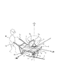
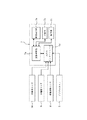
以下に、この発明の実施の形態を実施例によって、図面に基づき詳細に説明する。ここに、図1は、この発明の森林内光環境測定装置の一実施例としての移動式森林内光環境測定装置の外観を模式的に示す斜視図、図2は、その実施例の移動式森林内光環境測定装置の搭載機器の構成を示すブロック線図である。 Hereinafter, embodiments of the present invention will be described in detail with reference to the drawings. FIG. 1 is a perspective view schematically showing the appearance of a mobile forest light environment measuring apparatus as an embodiment of the forest light environment measuring apparatus according to the present invention. FIG. 2 is a mobile view of the embodiment. It is a block diagram which shows the structure of the mounting apparatus of the optical environment measuring apparatus in a forest.
この実施例の移動式森林内光環境測定装置は、図1に示すように、手押し用のハンドル1aと停止時用の二つの脚1b(図では片方のみ示す)とを持つフレーム1と、そのフレーム1の下部に枢支された一つだけの車輪2と、上記フレーム1上に設けられた天板3とを有して、その車輪2により走行面としての地表面Gに接地点Cで接地して測定作業者Wの手押し駆動で一輪走行する移動用一輪車4と、各々上記天板3上に搭載された、測定機器としてのデジタルカメラ5と、角度・加速度センサ6と、光データ記録装置および測定位置・方向演算装置としての通常のノート型パーソナルコンピュータ7並びに図示しないポータブル電源装置と、上記フレーム1の下部に搭載されて車輪2の回転を検出する車輪回転センサ8とを具えており、上記角度・加速度センサ6は内部に、互いに直角なx,y,z軸の三軸方向の移動用一輪車4の加速度を検出する加速度センサ9と、互いに直角なx,y,z軸の三軸周りの移動用一輪車4の回転角を検出する回転角センサ10とを収納している。
As shown in FIG. 1, the mobile forest light environment measuring apparatus of this embodiment includes a frame 1 having a handle 1a for pushing and two legs 1b for stopping (only one is shown in the figure), It has only one
ここで、移動用一輪車4は、市販の二輪車(例えば昭和ブリッジ販売株式会社製の二輪車 CC3-2FA)の左右方向へ延在する軸線上に並んだ元の二つの車輪を外し、代わりにそれらの車輪の中間位置に一つの車輪2のみを回転自在に取り付け、また機器を搭載し易いように元の合成樹脂製のボディを外し、代わりに平坦な合板製の天板3を、人が立ってハンドル1aを手で持った状態で概略水平になるように取り付けることで構成されている。そして車輪回転センサ8は、上記車輪2の車軸に直列に配置した二個のポテンシオメータ(例えば日本電産コパル株式会社製のCPP-45RBN 22.7kΩ)からなり、このポテンシオメータには角度を測定できない死角が存在するため、二個のポテンシオメータは、同時に死角とならないよう各々の死角が互いに180 度ずれて位置するように設置されている。
Here, the moving unicycle 4 removes the original two wheels arranged on the axis extending in the left-right direction of a commercially available motorcycle (for example, a motorcycle CC3-2FA manufactured by Showa Bridge Sales Co., Ltd.) At the middle position of the wheel, only one
また、角度・加速度センサ6は、市販のもの(例えば株式会社データ・テック製の三軸角度センサ GU-3024)にて構成され、図1に示すように、そこに収納された加速度センサ9は、そのセンサのx軸が、天板3の表面に平行に移動用一輪車4の前後方向に延在する当該移動用一輪車4固有の直角座標系のx軸と平行に延在し、そのセンサのy軸が、天板3の表面に平行に移動用一輪車4の左右方向に延在する当該移動用一輪車4固有の直角座標系のy軸と平行に延在し、そのセンサのz軸が、天板3の表面に垂直に移動用一輪車4の上下方向に延在する当該移動用一輪車4固有の直角座標系のz軸と平行に延在するように取り付けられ、またそこに収納されたジャイロからなる回転角センサ10は、そのセンサのx軸が当該移動用一輪車4固有の上記直角座標系のx軸と一致して前後方向に延在し、そのセンサのy軸が当該移動用一輪車4固有の上記直角座標系のy軸と一致して移動用一輪車4の左右方向に延在し、そのセンサのz軸が移動用一輪車4の車軸に対し車輪2の中心部分で直交して当該移動用一輪車4固有の上記直角座標系のz軸と一致して移動用一輪車4の上下方向に延在するように取り付けられている。そして上記図示しないポータブル電源装置は、バッテリ内蔵インバータ(例えばスワロー電機株式会社製のポータブル電源 Z-130)にて構成され、角度・加速度センサ6およびパーソナルコンピュータ7の電源としてAC100Vを出力する。
Further, the angle / acceleration sensor 6 is a commercially available one (for example, a triaxial angle sensor GU-3024 manufactured by Data Tech Co., Ltd.), and as shown in FIG. The x-axis of the sensor extends in parallel with the x-axis of the rectangular coordinate system unique to the moving unicycle 4 extending in the front-rear direction of the moving unicycle 4 in parallel to the surface of the top board 3. The y-axis extends parallel to the y-axis of the rectangular coordinate system inherent to the moving unicycle 4 extending in the left-right direction of the moving unicycle 4 parallel to the surface of the top board 3, and the z-axis of the sensor is A gyro mounted perpendicularly to the surface of the top plate 3 so as to extend in the vertical direction of the moving unicycle 4 so as to extend in parallel with the z-axis of the rectangular coordinate system unique to the moving unicycle 4 and housed therein The
さらにこの実施例では、角度・加速度センサ6の内部の加速度センサ9と回転角センサ10とがそれぞれ検出した三次元方向加速度と三次元方向角度とのデータが、RS232Cケーブルを介してパーソナルコンピュータ7に入力される。また、車輪回転センサ8を構成する二個のポテンシオメータの電源端子(端子間抵抗値固定の両端端子)同士が互いに並列に接続されて、その並列回路に20kΩの固定抵抗が直列に接続され、これら全体に単一乾電池四個直列による約6Vの電圧が印荷されており、上記二個のポテンシオメータの並列回路の両端の電圧(V0)と、それらのポテンシオメータの各々の出力端子(抵抗値可変の中間端子)の電圧(V1, V2)との計三つの電圧が、パーソナルコンピュータ7のカードスロット内に挿入されたAD変換カード(例えばラトックシステム株式会社製のREX-5054U )を介してそれぞれ独立にパーソナルコンピュータ7に入力される。
Furthermore, in this embodiment, the data of the three-dimensional direction acceleration and the three-dimensional direction angle respectively detected by the
さらに、デジタルカメラ5は、市販の一眼レフタイプのもので、森林内の全天の光環境の測定のために超広角レンズ(魚眼レンズ)5aを装着され、図1に示すように、この実施例ではその超広角レンズ5aが当該移動用一輪車4の上記固有の直角座標系のz軸と一致して上方へ向き、かつそのデジタルカメラ5の水平姿勢で上下に位置する部分が上記固有の直角座標系のx軸上に位置するように、角度・加速度センサ6のハウジングを介して天板3上に固定されており、そのデジタルカメラ5が森林内を撮影して出力する光データとしてのデジタル画像データは、例えばパーソナルコンピュータ7のUSB(Universal Serial Bus)端子を介してパーソナルコンピュータ7に入力される。
Further, the
そしてパーソナルコンピュータ7は、図2に示すように、CPU(中央処理ユニット)を持つ演算処理部7aと、液晶画面を持つ画面表示部7bと、メモリやハードディスクドライブ装置等を持つ記憶部7cと、上記カードスロットに挿入されるカードを含む入出力インターフェース7dと、キーボード等を持つ操作部7eとを有しており、これによりパーソナルコンピュータ7は、記憶部7c内にあらかじめ記憶した、当該パーソナルコンピュータ7を測定位置・方向演算装置として機能させる移動測定プログラムと当該パーソナルコンピュータ7を光データ記録装置および光データ解析装置として機能させる光データ記録・解析プログラムとの二種類のプログラムに基づいて、後述の如く、上記各センサ8〜10からのデータを、デジタルカメラ5からの光データと併せて画面表示部7bにより画面表示するとともに記憶部7c内に記録し、さらにそれらのデータから森林内の光環境を求めて出力する。なお、車輪回転センサ8を構成する上記二個のポテンシオメータの出力電圧V1, V2については、V1/V0 およびV2/V0 の値から、死角でない方の出力を選んで車輪2の回転角に換算する。
As shown in FIG. 2, the
この実施例の移動式森林内光環境測定装置を用いて森林内の光環境の移動測定を行う際には、先ず、パーソナルコンピュータ7の電源を入れて上記移動測定プログラムを起動するとともに、角度・加速度センサ6の電源を入れて加速度センサ9と回転角センサ10とを起動し、上記プログラムに基づいて作動するパーソナルコンピュータ7は、そのセンサ起動の際のx軸、y軸およびz軸の位置を基本座標軸として使用する。
When performing the movement measurement of the light environment in the forest using the mobile forest light environment measurement apparatus of this embodiment, first, the
次いで、測定作業者が当該移動用一輪車4を手押しで走行させると、パーソナルコンピュータ7は、車輪回転センサ8を構成するポテンシオメータの出力データから換算される車輪2の回転角と車輪2の外径とから当該移動用一輪車4の移動距離を時々刻々と求め、その移動距離を、回転角センサ10の出力データから得た当該移動用一輪車4の姿勢の三次元方向角度を用いて上記基本座標軸のx軸、y軸およびz軸方向の各成分に分解してデジタルカメラ5の現在位置を求め、また回転角センサ10の出力データから得た当該移動用一輪車4の姿勢の三次元方向角度を用いて現在のデジタルカメラ5の撮影方向の天頂角および方位角を求めて、それらを記憶部7cのハードディスクドライブ装置でハードディスクに記録する。
Next, when the measurement operator causes the moving unicycle 4 to travel by hand, the
そして測定作業者が、当該移動用一輪車4の移動走行中、あるいは適宜停止させたときに、パーソナルコンピュータ7は、デジタルカメラ5が超広角レンズ(魚眼レンズ)5aを用いて撮影して出力する完全にまたは実質的に全天の光データとしての画像データを、所定のデータ形式に処理して測定結果として、上記求めたデジタルカメラ5の現在位置および現在の撮影方向(画像上の上下左右と撮影時の方位との関係)と対応づけて記憶部7cのハードディスクドライブ装置でハードディスクに記録する。
When the measurement operator moves the traveling unicycle 4 while traveling, or when appropriately stopped, the
なお、天板3を当該移動用一輪車4の前後方向の地表面Gの傾きに対し正確に平行に維持しながら移動用一輪車4を手押しで走行させることは期待できないので、観測作業者毎に移動用一輪車4のハンドル1aを手で保持した時の平地での地表面Gに対する天板3の傾きをあらかじめ調べてパーソナルコンピュータ7に入力しておいて、パーソナルコンピュータ7が、回転角センサ10の出力データから得た回転角をその傾き分補正する。
In addition, since it cannot be expected that the moving unicycle 4 is driven by hand while maintaining the top plate 3 exactly parallel to the inclination of the ground surface G in the front-rear direction of the moving unicycle 4, it is possible to move for each observation worker. The inclination of the top plate 3 with respect to the ground surface G on a flat ground when the handle 1a of the unicycle 4 for the vehicle is held by hand is checked in advance and input to the
また、車輪回転センサ8の出力データに基づく車輪2の回転状態と、加速度センサ9の出力データに基づく加速度の発生状態とが対応しない場合(例えば車輪2が回転していないのに前後方向の加速度が検出された場合)には、移動用一輪車4に衝撃等による加速度が生じていて車輪2が実際の移動距離分回転していないと推定されるので、パーソナルコンピュータ7は、加速度センサ9が検出した加速度を二階積分してその加速度方向の移動距離を求め、その加速度から求めた移動距離を用いて、先に車輪2の回転角から求めた移動距離を補正する。
Further, when the rotation state of the
さらに、パーソナルコンピュータ7は、測定機器5の現在位置の変化から当該移動用一輪車4の移動軌跡を求めるとともに、画面表示部7bの液晶画面上にその求めた当該移動用一輪車4の移動軌跡を地図あるいは平面図上で表示し、その画面表示部7bの液晶画面上に、測定機器5の上記測定結果も同時に、あるいは画面を切り替えて表示する。
Further, the
一方、別途森林外の開地では、上記デジタルカメラ5と同一仕様のデジタルカメラが撮影方向を鉛直上方へ向けられて設置され、そのデジタルカメラが所定時間ごとに撮影して出力した林外光データを、データロガー(記録計)(例えば米国LI-COR, inc.製で盟和商事株式会社が輸入販売しているデータロガー LI-1400)が時刻データとともに記録する。
On the other hand, in open land outside the forest, a digital camera with the same specifications as the
そして、パーソナルコンピュータ7は、当該移動式光環境測定装置での移動測定終了後に、上記光環境解析プログラムを実行することにて、記憶部7cのハードディスクドライブ装置でハードディスクから、測定中のデジタルカメラ5の位置および撮影方向と、デジタルカメラ5が撮影した全天の画像データ(光データ)とを読み出すとともに、上記データロガーから林外光データを林外光測定値として時刻データとともに入力して、デジタルカメラ5の全天画像データ上の輝度値を上記林外光測定値で除して相対照度値に換算し、それを森林内光環境特性の時空間分布データとして、画面表示部7bの液晶画面上への表示や記憶部7cのハードディスクドライブ装置でのハードディスクへの記録等の形態で出力する。
Then, the
従って、この実施例の移動式光環境測定装置によれば、GPSの利用できない森林内においても天頂角別光環境の空間分布を容易に測定することができ、また、位置および方向情報と光環境情報とを同時に記録するので、その光環境情報を容易に解析および利用することができ、しかも超広角レンズ(魚眼レンズ)5aを使用しているため一枚ずつの画像が全天の光データを記録するので、少ないデータ量で多くの情報を記録することができる。 Therefore, according to the mobile light environment measuring apparatus of this embodiment, the spatial distribution of the light environment according to the zenith angle can be easily measured even in a forest where GPS cannot be used, and the position and direction information and the light environment can be measured. Since information is recorded at the same time, the light environment information can be easily analyzed and used, and the super wide-angle lens (fisheye lens) 5a is used so that each image records the light data of the whole sky. Therefore, a large amount of information can be recorded with a small amount of data.
また、この実施例の移動式光環境測定装置によれば、測定位置・方向演算装置としてのパーソナルコンピュータ7が、移動用一輪車4の位置を継続的に求め、その位置の変化に基づき移動用一輪車4の移動経路を求める移動経路演算部として機能するとともに、その求められた移動経路を画面上に出力する移動経路表示部としても機能することから、移動測定中の測定作業者や、その後に測定データを分析する研究者等が、移動測定中の移動用一輪車4の移動経路を画面上で確認できるので、移動測定中の測定作業者は常に現在位置を確認し得て、森林内の多点測定やライン測定、面測定等を自由に行うことができるとともに森林内での遭難の危険等を免れることもでき、また測定データを分析する研究者は地形等のデータを併せて参照し得て、より詳細な分析を行うことができる。
Further, according to the mobile optical environment measuring device of this embodiment, the
そして、この実施例の移動式光環境測定装置によれば、加速度センサ9が、移動用一輪車4の前後、左右および上下方向に延在する互いに直角な三軸方向の、その移動用一輪車4の加速度を検出し、測定位置・方向演算装置としてのパーソナルコンピュータ7が、デジタルカメラ5の位置および撮影方向を求めるためにその加速度も用いるので、移動用一輪車4に衝撃等による加速度が生じた場合でも、デジタルカメラ5の位置および撮影方向を求める際の誤差を少なくすることができる。
Then, according to the mobile optical environment measuring apparatus of this embodiment, the
以上、図示例に基づき説明したが、この発明は上述の例に限定されるものでなく、例えば、超広角レンズを装着されたデジタルカメラは、静止画用でなく動画用のいわゆるビデオカメラでも良く、また測定機器として、超広角レンズを装着されたデジタルカメラに加えて、光量子センサ等の他の光センサをさらに具えていても良い。 Although the present invention has been described based on the illustrated examples, the present invention is not limited to the above-described example. For example, a digital camera equipped with an ultra-wide-angle lens may be a so-called video camera for moving images instead of still images. Further, as a measuring instrument, in addition to a digital camera equipped with an ultra-wide-angle lens, another optical sensor such as a photon sensor may be further provided.
さらに、この発明においては、移動用一輪車は、測定作業者の手押しを補助するためあるいは、測定作業者がハンドルを保持するだけで自走するための、モータ等の動力源を搭載していても良い。そしてこの発明においては、移動用一輪車は手押しに限らず、馬やロバ等の動物が装具でハンドル等を保持して走行させるものとしても良い。 Further, according to the present invention, the unicycle for movement may be equipped with a power source such as a motor for assisting the measurement operator's hand or for the measurement operator to simply run by holding the handle. good. In the present invention, the moving unicycle is not limited to being pushed by hand, and an animal such as a horse or a donkey may be allowed to travel while holding a handle or the like with a brace.
かくしてこの発明の森林内光環境測定装置によれば、GPSの利用できない森林内においても天頂角別光環境の空間分布を容易に測定することができ、また、位置および方向情報と光環境情報とを同時に記録するので、その光環境情報を容易に解析および利用することができ、しかも超広角レンズ(魚眼レンズ)を使用しているため一枚ずつの画像が全天の光データを記録するので、少ないデータ量で多くの情報を記録することができる。 Thus, according to the in-forest light environment measuring apparatus of the present invention, it is possible to easily measure the spatial distribution of the light environment according to the zenith angle even in the forest where GPS cannot be used. Since the optical environment information can be easily analyzed and used, and since the super wide-angle lens (fisheye lens) is used, each image records all sky optical data. A large amount of information can be recorded with a small amount of data.
1 フレーム
1a ハンドル
1b 脚
2 車輪
3 天板
4 台車
5 デジタルカメラ
5a 超広角レンズ
6 角度・加速度センサ
7 パーソナルコンピュータ
7a 演算処理部
7b 画面表示部
7c 記憶部
7d 入出力インターフェース
7e 操作部
8 車輪回転センサ
9 加速度センサ
10 回転角センサ
1 frame
1a Handle
5a Super Wide Angle Lens 6 Angle /
7a Arithmetic processing part
7b Screen display
7c Memory unit
7d I / O interface
Claims (3)
前記測定機器を搭載し、一つの車輪で走行面に接して走行する移動用一輪車と、を具え、
前記測定機器は、
超広角レンズを装着され、その超広角レンズを上方へ向けられたデジタルカメラと、
前記デジタルカメラが撮影して出力した光データを前記デジタルカメラの位置および撮影方向と併せて記録する光データ記録装置と、を有し、
前記移動用一輪車は、
互いに直角な三軸周りの前記移動用一輪車の回転角を検出する回転角センサと、
前記車輪の回転を検出する車輪回転センサと、
前記回転角センサからの自律航法用情報と、前記車輪回転センサからの移動距離情報とに基づき、前記デジタルカメラによる撮影の際のそのデジタルカメラの位置および撮影方向を求めて前記光データ記録装置に与える測定位置・方向演算装置と、を有することを特徴とする、移動式光環境測定装置。 Measuring equipment for measuring the light environment;
A moving unicycle that is mounted with the measuring device and travels in contact with the traveling surface with one wheel;
The measuring instrument is
A digital camera equipped with a super-wide-angle lens and facing the super-wide-angle lens upward;
An optical data recording device that records optical data photographed and output by the digital camera together with a position and a photographing direction of the digital camera;
The mobile unicycle is
A rotation angle sensor for detecting a rotation angle of the moving unicycle around three axes perpendicular to each other;
A wheel rotation sensor for detecting rotation of the wheel;
Based on the information for autonomous navigation from the rotation angle sensor and the movement distance information from the wheel rotation sensor, the optical data recording device obtains the position and shooting direction of the digital camera at the time of shooting by the digital camera. A mobile optical environment measuring device, comprising: a measuring position / direction calculating device for giving.
前記移動用一輪車の位置を継続的に求め、その位置の変化に基づき前記移動用一輪車の移動経路を求める移動経路演算部と、
前記求められた移動経路を画面上に出力する移動経路表示部と、
を有することを特徴とする、請求項1から5までの何れか記載の移動式光環境測定装置。 The measurement position / direction computing device is:
A movement path calculation unit that continuously obtains the position of the unicycle for movement, and obtains a movement path of the unicycle for movement based on a change in the position;
A travel route display unit for outputting the obtained travel route on a screen;
The mobile optical environment measuring device according to any one of claims 1 to 5, characterized by comprising:
前記測定位置・方向演算装置は、前記デジタルカメラの位置および撮影方向を求めるために前記加速度センサからの自律航法用情報も用いることを特徴とする、請求項1から6までの何れか記載の移動式光環境測定装置。 The moving unicycle has an acceleration sensor that detects acceleration of the moving unicycle in three axial directions perpendicular to each other.
The movement according to any one of claims 1 to 6, wherein the measurement position / direction computing device also uses information for autonomous navigation from the acceleration sensor to determine the position and shooting direction of the digital camera. Type light environment measuring device.
Priority Applications (2)
| Application Number | Priority Date | Filing Date | Title |
|---|---|---|---|
| JP2004102832A JP2005291734A (en) | 2004-03-31 | 2004-03-31 | Forest light environment measurement device |
| US11/091,379 US20050219517A1 (en) | 2004-03-31 | 2005-03-29 | Light environment measuring system suitable for measuring in the forest |
Applications Claiming Priority (1)
| Application Number | Priority Date | Filing Date | Title |
|---|---|---|---|
| JP2004102832A JP2005291734A (en) | 2004-03-31 | 2004-03-31 | Forest light environment measurement device |
Publications (1)
| Publication Number | Publication Date |
|---|---|
| JP2005291734A true JP2005291734A (en) | 2005-10-20 |
Family
ID=35053903
Family Applications (1)
| Application Number | Title | Priority Date | Filing Date |
|---|---|---|---|
| JP2004102832A Pending JP2005291734A (en) | 2004-03-31 | 2004-03-31 | Forest light environment measurement device |
Country Status (2)
| Country | Link |
|---|---|
| US (1) | US20050219517A1 (en) |
| JP (1) | JP2005291734A (en) |
Cited By (6)
| Publication number | Priority date | Publication date | Assignee | Title |
|---|---|---|---|---|
| JP2011013036A (en) * | 2009-06-30 | 2011-01-20 | Nikken Sekkei Ltd | Device for determining presence or absence of direct light, device for controlling electric blind, method for determining presence or absence of direct light and method for controlling electric blind |
| JP5555367B1 (en) * | 2013-11-18 | 2014-07-23 | 株式会社シーティーエス | Compaction and leveling management system |
| WO2016027740A1 (en) * | 2014-08-20 | 2016-02-25 | 株式会社 トプコン | Illuminance measurement system |
| JP2017026411A (en) * | 2015-07-21 | 2017-02-02 | 株式会社トプコン | Illuminance measurement system |
| JP2017072391A (en) * | 2015-10-05 | 2017-04-13 | 株式会社トプコン | Measuring apparatus, measuring method and program |
| JP2017072442A (en) * | 2015-10-06 | 2017-04-13 | 株式会社トプコン | Electromagnetic wave measuring device, electromagnetic wave measuring method, and program |
Families Citing this family (8)
| Publication number | Priority date | Publication date | Assignee | Title |
|---|---|---|---|---|
| JP3837552B2 (en) * | 2003-07-08 | 2006-10-25 | 国立大学法人名古屋大学 | Mobile optical environment measurement device |
| US7232987B2 (en) * | 2005-05-25 | 2007-06-19 | Victor Webbeking | Instrument and method to measure available light energy for photosynthesis |
| ES2359797B1 (en) * | 2009-11-17 | 2012-03-30 | Simulacions Òptiques, S.L. | PHOTOMETRIC DEVICE ELECTRO-OPTICAL DYNAMIC AND ITS PROCEDURE FOR THE DYNAMIC MEASUREMENT OF THE AMOUNT AND DISTRIBUTION OF POLYCHROMEDIC LIGHT. |
| US11243309B2 (en) | 2015-02-16 | 2022-02-08 | Northwest Instrument Inc. | Ranging system and ranging method |
| CN104634222A (en) * | 2015-02-16 | 2015-05-20 | 上海诺司纬光电仪器有限公司 | A distance measuring system and a distance measuring method |
| US12055414B2 (en) | 2015-02-16 | 2024-08-06 | Northwest Instrument Inc. | Ranging system and ranging method |
| CN109579823A (en) * | 2017-09-28 | 2019-04-05 | 南京淳泰控制设备有限公司 | A kind of orientation attitude measurement instrument |
| CN109373988B (en) * | 2018-12-05 | 2023-08-01 | 中铁十二局集团有限公司 | Instrument and method for measuring trackless construction of overhead contact system in tunnel |
Family Cites Families (3)
| Publication number | Priority date | Publication date | Assignee | Title |
|---|---|---|---|---|
| JP3728511B2 (en) * | 2003-07-07 | 2005-12-21 | 国立大学法人名古屋大学 | Mobile three-dimensional structure measuring device |
| JP3837552B2 (en) * | 2003-07-08 | 2006-10-25 | 国立大学法人名古屋大学 | Mobile optical environment measurement device |
| DE10339366A1 (en) * | 2003-08-27 | 2005-03-24 | Dr. Johannes Heidenhain Gmbh | Method and device for controlling a light source of a position measuring device |
-
2004
- 2004-03-31 JP JP2004102832A patent/JP2005291734A/en active Pending
-
2005
- 2005-03-29 US US11/091,379 patent/US20050219517A1/en not_active Abandoned
Cited By (6)
| Publication number | Priority date | Publication date | Assignee | Title |
|---|---|---|---|---|
| JP2011013036A (en) * | 2009-06-30 | 2011-01-20 | Nikken Sekkei Ltd | Device for determining presence or absence of direct light, device for controlling electric blind, method for determining presence or absence of direct light and method for controlling electric blind |
| JP5555367B1 (en) * | 2013-11-18 | 2014-07-23 | 株式会社シーティーエス | Compaction and leveling management system |
| WO2016027740A1 (en) * | 2014-08-20 | 2016-02-25 | 株式会社 トプコン | Illuminance measurement system |
| JP2017026411A (en) * | 2015-07-21 | 2017-02-02 | 株式会社トプコン | Illuminance measurement system |
| JP2017072391A (en) * | 2015-10-05 | 2017-04-13 | 株式会社トプコン | Measuring apparatus, measuring method and program |
| JP2017072442A (en) * | 2015-10-06 | 2017-04-13 | 株式会社トプコン | Electromagnetic wave measuring device, electromagnetic wave measuring method, and program |
Also Published As
| Publication number | Publication date |
|---|---|
| US20050219517A1 (en) | 2005-10-06 |
Similar Documents
| Publication | Publication Date | Title |
|---|---|---|
| JP3728511B2 (en) | Mobile three-dimensional structure measuring device | |
| JP2005291734A (en) | Forest light environment measurement device | |
| JP7125554B2 (en) | Separate vehicle LIDAR data collection pod | |
| CN106461391B (en) | measuring system | |
| Yanco et al. | " Where am I?" Acquiring situation awareness using a remote robot platform | |
| JP7718472B2 (en) | Information processing system and program | |
| JP3837552B2 (en) | Mobile optical environment measurement device | |
| US9316489B2 (en) | Laser frame tracer | |
| US20020124424A1 (en) | Contour measuring device and method | |
| US20160065932A1 (en) | Device and system for three-dimensional scanning, and method thereof | |
| JP3735722B2 (en) | Unicycle for mobile observation | |
| CN109460040A (en) | It is a kind of that map system and method are established by mobile phone shooting photo array floor | |
| CN112631431A (en) | AR (augmented reality) glasses pose determination method, device and equipment and storage medium | |
| Núnez et al. | Data Fusion Calibration for a 3D Laser Range Finder and a Camera using Inertial Data. | |
| Goebel et al. | Backpack System for Capturing 3D Point Clouds of Forests | |
| CN206891431U (en) | A kind of real estate surveying managing device | |
| US8903163B2 (en) | Using gravity measurements within a photogrammetric adjustment | |
| TW201242324A (en) | System and method for testing and simulating state | |
| TWM656648U (en) | Backpack sidewalk facility inspection system | |
| Lobo et al. | Integration of inertial information with vision towards robot autonomy | |
| CN111238439B (en) | Angular deviation measuring system | |
| CN213874462U (en) | Plant phenotype detection robot | |
| CN110696951A (en) | A self-driving two-wheeled self-balancing vehicle and its control method | |
| CN211576208U (en) | Attitude information collection equipment | |
| Lundström et al. | LiDAR robot: Mapping of rooms in 2D |
Legal Events
| Date | Code | Title | Description |
|---|---|---|---|
| A131 | Notification of reasons for refusal |
Free format text: JAPANESE INTERMEDIATE CODE: A131 Effective date: 20060110 |
|
| A521 | Written amendment |
Free format text: JAPANESE INTERMEDIATE CODE: A523 Effective date: 20060313 |
|
| A131 | Notification of reasons for refusal |
Free format text: JAPANESE INTERMEDIATE CODE: A131 Effective date: 20060704 |
|
| A02 | Decision of refusal |
Free format text: JAPANESE INTERMEDIATE CODE: A02 Effective date: 20070109 |