EP1510677A2 - Steuervorrichtung für eine Brennkraftmaschine - Google Patents
Steuervorrichtung für eine Brennkraftmaschine Download PDFInfo
- Publication number
- EP1510677A2 EP1510677A2 EP04020186A EP04020186A EP1510677A2 EP 1510677 A2 EP1510677 A2 EP 1510677A2 EP 04020186 A EP04020186 A EP 04020186A EP 04020186 A EP04020186 A EP 04020186A EP 1510677 A2 EP1510677 A2 EP 1510677A2
- Authority
- EP
- European Patent Office
- Prior art keywords
- opening degree
- intake pipe
- throttle valve
- pipe pressure
- cylinder
- Prior art date
- Legal status (The legal status is an assumption and is not a legal conclusion. Google has not performed a legal analysis and makes no representation as to the accuracy of the status listed.)
- Granted
Links
- 238000002485 combustion reaction Methods 0.000 title claims abstract description 48
- 230000004044 response Effects 0.000 claims abstract description 49
- 238000000034 method Methods 0.000 abstract description 18
- 230000008859 change Effects 0.000 description 24
- 238000011144 upstream manufacturing Methods 0.000 description 20
- 239000000446 fuel Substances 0.000 description 13
- 238000002347 injection Methods 0.000 description 9
- 239000007924 injection Substances 0.000 description 9
- 230000006870 function Effects 0.000 description 7
- 230000001186 cumulative effect Effects 0.000 description 3
- 230000007246 mechanism Effects 0.000 description 3
- 230000000694 effects Effects 0.000 description 2
- 230000006835 compression Effects 0.000 description 1
- 238000007906 compression Methods 0.000 description 1
- 230000007423 decrease Effects 0.000 description 1
- 230000001627 detrimental effect Effects 0.000 description 1
- 238000006073 displacement reaction Methods 0.000 description 1
- 238000002474 experimental method Methods 0.000 description 1
- 239000012530 fluid Substances 0.000 description 1
- 230000012447 hatching Effects 0.000 description 1
- 238000012986 modification Methods 0.000 description 1
- 230000004048 modification Effects 0.000 description 1
- 230000002093 peripheral effect Effects 0.000 description 1
- 230000008569 process Effects 0.000 description 1
- 238000000746 purification Methods 0.000 description 1
- 230000001629 suppression Effects 0.000 description 1
Images


Classifications
-
- F—MECHANICAL ENGINEERING; LIGHTING; HEATING; WEAPONS; BLASTING
- F02—COMBUSTION ENGINES; HOT-GAS OR COMBUSTION-PRODUCT ENGINE PLANTS
- F02D—CONTROLLING COMBUSTION ENGINES
- F02D41/00—Electrical control of supply of combustible mixture or its constituents
- F02D41/0002—Controlling intake air
-
- F—MECHANICAL ENGINEERING; LIGHTING; HEATING; WEAPONS; BLASTING
- F02—COMBUSTION ENGINES; HOT-GAS OR COMBUSTION-PRODUCT ENGINE PLANTS
- F02D—CONTROLLING COMBUSTION ENGINES
- F02D11/00—Arrangements for, or adaptations to, non-automatic engine control initiation means, e.g. operator initiated
- F02D11/06—Arrangements for, or adaptations to, non-automatic engine control initiation means, e.g. operator initiated characterised by non-mechanical control linkages, e.g. fluid control linkages or by control linkages with power drive or assistance
- F02D11/10—Arrangements for, or adaptations to, non-automatic engine control initiation means, e.g. operator initiated characterised by non-mechanical control linkages, e.g. fluid control linkages or by control linkages with power drive or assistance of the electric type
- F02D11/105—Arrangements for, or adaptations to, non-automatic engine control initiation means, e.g. operator initiated characterised by non-mechanical control linkages, e.g. fluid control linkages or by control linkages with power drive or assistance of the electric type characterised by the function converting demand to actuation, e.g. a map indicating relations between an accelerator pedal position and throttle valve opening or target engine torque
-
- F—MECHANICAL ENGINEERING; LIGHTING; HEATING; WEAPONS; BLASTING
- F02—COMBUSTION ENGINES; HOT-GAS OR COMBUSTION-PRODUCT ENGINE PLANTS
- F02D—CONTROLLING COMBUSTION ENGINES
- F02D41/00—Electrical control of supply of combustible mixture or its constituents
- F02D41/02—Circuit arrangements for generating control signals
- F02D41/18—Circuit arrangements for generating control signals by measuring intake air flow
-
- F—MECHANICAL ENGINEERING; LIGHTING; HEATING; WEAPONS; BLASTING
- F02—COMBUSTION ENGINES; HOT-GAS OR COMBUSTION-PRODUCT ENGINE PLANTS
- F02D—CONTROLLING COMBUSTION ENGINES
- F02D41/00—Electrical control of supply of combustible mixture or its constituents
- F02D41/02—Circuit arrangements for generating control signals
- F02D41/14—Introducing closed-loop corrections
- F02D41/1401—Introducing closed-loop corrections characterised by the control or regulation method
- F02D2041/1413—Controller structures or design
- F02D2041/1431—Controller structures or design the system including an input-output delay
-
- F—MECHANICAL ENGINEERING; LIGHTING; HEATING; WEAPONS; BLASTING
- F02—COMBUSTION ENGINES; HOT-GAS OR COMBUSTION-PRODUCT ENGINE PLANTS
- F02D—CONTROLLING COMBUSTION ENGINES
- F02D2200/00—Input parameters for engine control
- F02D2200/02—Input parameters for engine control the parameters being related to the engine
- F02D2200/04—Engine intake system parameters
- F02D2200/0402—Engine intake system parameters the parameter being determined by using a model of the engine intake or its components
-
- F—MECHANICAL ENGINEERING; LIGHTING; HEATING; WEAPONS; BLASTING
- F02—COMBUSTION ENGINES; HOT-GAS OR COMBUSTION-PRODUCT ENGINE PLANTS
- F02D—CONTROLLING COMBUSTION ENGINES
- F02D2200/00—Input parameters for engine control
- F02D2200/02—Input parameters for engine control the parameters being related to the engine
- F02D2200/04—Engine intake system parameters
- F02D2200/0406—Intake manifold pressure
-
- F—MECHANICAL ENGINEERING; LIGHTING; HEATING; WEAPONS; BLASTING
- F02—COMBUSTION ENGINES; HOT-GAS OR COMBUSTION-PRODUCT ENGINE PLANTS
- F02D—CONTROLLING COMBUSTION ENGINES
- F02D35/00—Controlling engines, dependent on conditions exterior or interior to engines, not otherwise provided for
- F02D35/0007—Controlling engines, dependent on conditions exterior or interior to engines, not otherwise provided for using electrical feedback
-
- F—MECHANICAL ENGINEERING; LIGHTING; HEATING; WEAPONS; BLASTING
- F02—COMBUSTION ENGINES; HOT-GAS OR COMBUSTION-PRODUCT ENGINE PLANTS
- F02D—CONTROLLING COMBUSTION ENGINES
- F02D41/00—Electrical control of supply of combustible mixture or its constituents
- F02D41/30—Controlling fuel injection
- F02D41/32—Controlling fuel injection of the low pressure type
-
- Y—GENERAL TAGGING OF NEW TECHNOLOGICAL DEVELOPMENTS; GENERAL TAGGING OF CROSS-SECTIONAL TECHNOLOGIES SPANNING OVER SEVERAL SECTIONS OF THE IPC; TECHNICAL SUBJECTS COVERED BY FORMER USPC CROSS-REFERENCE ART COLLECTIONS [XRACs] AND DIGESTS
- Y02—TECHNOLOGIES OR APPLICATIONS FOR MITIGATION OR ADAPTATION AGAINST CLIMATE CHANGE
- Y02T—CLIMATE CHANGE MITIGATION TECHNOLOGIES RELATED TO TRANSPORTATION
- Y02T10/00—Road transport of goods or passengers
- Y02T10/10—Internal combustion engine [ICE] based vehicles
- Y02T10/40—Engine management systems
Definitions
- the present invention relates to a control device of an internal combustion engine.
- a control device for an internal combustion engine As a control device for an internal combustion engine, one has been known which judges a required torque based on an accelerator opening degree etc. and controls operation of a fuel injector or an opening degree of a throttle valve so as to realized this required torque.
- a target fuel injection amount and target cylinder air filling amount or target value of equivalent value of cylinder air filling amount (that is, for example, cylinder intake air flow rate or cylinder air filling rate)
- the operation of the fuel injector and the opening degree of the throttle valve are controlled so that the actual fuel injection amount and cylinder air filling amount (or its equivalent value) matches the target fuel injection amount and target cylinder air filling amount (or target value of equivalent value of cylinder air filling amount).
- the cylinder air filling amount (or its equivalent value) is more specifically adjusted by controlling the opening degree of the throttle valve (hereinafter referred to as the "throttle opening degree") to a target opening degree set in accordance with the target cylinder air filling amount (or target value of equivalent value of cylinder air filling amount), but even if making the throttle opening degree the target opening degree, a certain time is required until the actual cylinder air filling amount (or its equivalent value) becomes the target cylinder air filling amount (or target value of equivalent value of the cylinder air filling amount). That is, a change of the cylinder air filling amount (or its equivalent value) occurs with a delay from the change of the throttle opening degree.
- An object of the present invention is to provide a control device of an internal combustion engine finding a response time constant ⁇ of a cylinder air filling amount or its equivalent value by a simpler method.
- a control device of an internal combustion engine calculating a response time constant of a cylinder air filling amount or its equivalent value when an opening degree of a throttle valve is changed to a target opening degree, provided with means for setting the target opening degree, means for finding a target intake pipe pressure as a value of convergence of an intake pipe pressure at a downstream side of the throttle valve when maintaining the opening degree of the throttle valve at the target opening degree, means for finding a current intake pipe pressure as an intake pipe pressure at a downstream side of the throttle valve when changing the opening degree of the throttle valve to the target opening degree, means for finding a throttle valve air passage flow rate, and means for finding a cylinder intake air flow rate and calculating the response time constant based on the target intake pipe pressure, the current intake pipe pressure, the throttle valve air passage flow rate, and the cylinder intake air flow rate.
- the response time constant of the cylinder air filling amount or its equivalent value is found by calculation based on the target intake pipe pressure, the current intake pipe pressure, the throttle valve air passage flow rate, and the cylinder intake air flow rate. Therefore, the response time constant of the cylinder air filling amount or its equivalent value can be found more simply.
- the means for setting the target opening degree of the throttle valve has means for finding a cylinder air filling amount corresponding to the required torque or its equivalent value and finding a required intake pipe pressure as the intake pipe pressure at the downstream side of the throttle valve for realizing this and, when the required intake pipe pressure is larger than a predetermined pressure, finding an opening degree of the throttle valve for realizing the predetermined pressure as a corrected target opening degree and setting the corrected target opening degree as the target opening degree.
- the effect of the change in opening degree of the throttle value on the cylinder air filling amount or the intake pipe pressure at the downstream side of the throttle valve becomes extremely small in the region where the throttle valve opening degree is large, that is, the region where the intake pipe pressure at the downstream side of the throttle valve is large. Therefore, in the region where the throttle valve opening degree is large, that is, in the region where the intake pipe pressure at the downstream side of the throttle valve is large, even if the required torque changes slightly and the cylinder air filling amount or its equivalent value corresponding to this changes slightly, to realize a change of the required intake pipe pressure corresponding to this, the opening degree of the throttle valve fluctuates largely. Sometimes there is hunting of the opening degree of the throttle valve.
- the opening degree of the throttle valve for realizing the predetermined pressure is found as the corrected target opening degree and the corrected target opening degree is set as the target opening degree, so by suitably setting the predetermined pressure, it is possible to suppress hunting of the throttle valve opening degree.
- the means for setting the target opening degree of the throttle valve has means for finding a cylinder air filling amount corresponding to the required torque or its equivalent value and finding a required intake pipe pressure as the intake pipe pressure at the downstream side of the throttle valve for realizing this and, when the required intake pipe pressure is larger than a predetermined pressure, finding an opening degree of the throttle valve for realizing the predetermined pressure as a corrected target opening degree and setting the corrected target opening degree plus a correction value determined based on at least an engine speed as the target opening degree.
- the opening degree of the throttle valve for realizing the required intake pipe pressure is set as the target opening degree.
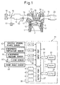
- FIG. 1 is a schematic view of an example of the case of application of the control device of the internal combustion engine of the present invention to a cylinder injection type spark ignition internal combustion engine. Note that the present invention may also be applied to another spark ignition internal combustion engine or a compression ignition internal combustion engine.
- the engine body 1 is provided with a cylinder block 2, a piston 3 moving reciprocally inside the cylinder block 2, and a cylinder head 4 fixed on the cylinder block 2.
- Each piston 3 and the cylinder head 4 have a combustion chamber 5 formed between them.
- the cylinder head 4 has an intake valve 6, intake port 7, exhaust valve 8, and exhaust port 9 arranged for each cylinder.
- the intake valve 6 and exhaust valve 8 are provided with variable valve timing mechanisms 23 and 24 for changing the operating timings of the valves.
- a spark plug 10 is arranged at the center of the inside wall of the cylinder head 4 and a fuel injector 11 is arranged at a peripheral portion of the inside wall of the cylinder head 4.
- the top surface of the piston 3 is formed with a cavity 12 extending from below the fuel injector 11 to below the spark plug 10.
- the intake port 7 of each cylinder is connected with a surge tank 14 through the downstream side intake pipe 13.
- the surge tank 14 is connected with an air cleaner 16 through the upstream side intake pipe 15.
- the intake pipe 15 has a throttle valve 18 driven by a step motor 17 arranged in it.
- the exhaust port 9 of each cylinder is connected with an exhaust pipe 19. This exhaust pipe 19 is connected to an exhaust purification device 20.
- An electronic control unit (ECU) 31 is comprised of a digital computer comprising a random access memory (RAM) 33, a read only memory (ROM) 34, a microprocessor (CPU) 35, an input port 36, and an output port 37 connected with each other through a two-way bus 32.
- the intake pipe 13 is provided with an intake pipe pressure sensor 40 for detecting a pressure inside the intake pipe at the downstream side from the throttle valve 18.
- the intake pipe pressure sensor 40 generates an output voltage proportional to the intake pipe pressure.
- the output voltage is input to the input port 36 through a corresponding A/D converter 38.
- a throttle opening degree sensor 43 for detecting an opening degree of the throttle valve 18, an atmospheric pressure sensor 44 for detecting the pressure of the atmosphere around the internal combustion engine or the pressure of the air taken into the intake pipe 15 (intake pressure), and an atmospheric temperature sensor 45 for detecting the temperature of the atmosphere around the internal combustion engine or the temperature of the air taken into the intake pipe 15 (intake temperature) are provided.
- the output voltages of these sensors are input through the corresponding AD converters 38 to the input port 36.
- the accelerator pedal 46 has a load sensor 47 for generating an output voltage proportional to the amount of depression of the accelerator pedal 46 (hereinafter referred to as the "amount of accelerator depression") connected to it.
- the output voltage of the load sensor 47 is input through the corresponding AD converter 38 to the input port 36.
- a crank angle sensor 48 generates an output pulse each time for example the crankshaft rotates 30 degrees. This output pulse is input to the input port 36.
- the CPU 35 calculates the engine speed from the output pulses of the crank angle sensor 48.
- the output port 37 is connected through the corresponding drive circuits 39 to the spark plugs 10, fuel injectors 11, step motor 17, etc. Further, the variable valve timing mechanisms 23 and 24 are also controlled by the ECU 31.
- the internal combustion engine is controlled using such models.
- a model of the intake system is created based on a throttle model M21, intake pipe model M22, and intake valve model M23.
- the control device of the internal combustion engine is provided with equations showing these models explained below.
- the throttle model M21 is a model of a throttle valve.
- the throttle valve air passage flow rate mt (g/s) is expressed by the following equation (2).
- Pa (kPa) is the atmospheric pressure
- Ta (K) is the atmospheric temperature
- Pm (kPa) is the pressure inside the intake pipe at the downstream side from the throttle valve (hereinafter called the "downstream side intake pipe pressure")
- R is the gas constant.
- ⁇ is the flow coefficient in a throttle valve, is a function of the throttle valve opening degree ⁇ t, and is determined from a map as shown in FIG. 2.
- At (m 2 ) indicates the cross-sectional area of the opening of the throttle valve (hereinafter referred to as the "throttle opening area”) and is a function of the throttle valve opening degree ⁇ t. Note that if making ⁇ At combining the flow coefficient ⁇ and the throttle opening area At a function F( ⁇ t) having just the throttle valve opening degree ⁇ t as a variable, equation (2) can be rewritten to equation (3):
- ⁇ (Pm/Pa) is a function shown in the following equation (4).
- This function ⁇ (Pm/Pa) can be expressed as a graph such as shown in FIG. 3, so it is possible to store this graph in the ROM of the ECU as a map and not use equation (4) for calculation, but find the value of ⁇ (Pm/Pa) from the map.
- Equation (2) to equation (4) of the throttle model M21 are obtained by making the pressure of the gas upstream of the throttle valve 18 the atmospheric pressure Pa, making the temperature of the gas upstream of the throttle valve 18 the atmospheric temperature Ta, and making the pressure of the gas passing through the throttle valve 18 the downstream side intake pipe pressure Pm, applying the law of the conservation of mass, the law of the conservation of energy, and the law of the conservation of motion to the model of the throttle valve 18 as shown in FIG. 4, and utilizing the gas state equation, definition of the ratio of specific heat, and Mayer's formula.
- the intake pipe model M22 is a model of the part 13' of the intake pipe etc. from the throttle valve to the intake valve (hereinafter called the "intake pipe part").
- the downstream side intake pipe pressure Pm (kPa) and the downstream side intake pipe temperature Tm (K) can be expressed as shown in the following equation (5) and equation (6).
- mc (g/s) is the cylinder intake air flow rate
- Vm (m 3 ) is a constant equal to the volume of the intake pipe part 13'.
- dPm dt ⁇ ⁇ R Vm ⁇ (mt ⁇ Ta - mc ⁇ Tm)
- the intake valve model M23 is a model of the intake valve.
- the cylinder intake air flow rate mc is expressed by equation (9).
- a and b in equation (9) are compliance parameters determined based on at least the engine speed NE.
- a map is prepared in advance and the map is searched to find them in accordance with need.
- the intake and exhaust valves are provided with variable valve timing mechanisms 23 and 24. Since the operating timings of the intake and exhaust valves can be changed, the compliance parameters a and b are determined based on the phase angles expressing the operating timings of the intake and exhaust valves.
- mc a ⁇ Pm - b
- the cylinder air filling amount Mc showing the amount of air filled into the combustion chamber 5 at the time the intake valve 6 is closed is finally set at the time the intake valve 6 is closed (when intake valve is closed) and is proportional to the pressure in the combustion chamber 5 at the time the intake valve is closed. Further, the pressure inside the combustion chamber 5 at the time the intake valve is closed can be deemed as equal to the pressure of the gas upstream of the intake valve, that is, the downstream side intake pipe pressure Pm. Therefore, the cylinder air filling amount Mc can be approximated as being proportional to the downstream side intake pipe pressure Pm.
- the cylinder intake air flow rate mc (explained in detail below) since the cylinder air filling amount Mc is proportional to the downstream side intake pipe pressure Pm, the cylinder intake air flow rate mc can also be considered to be proportional to the downstream side intake pipe pressure Pm. From this, the above equation (9) is obtained theoretically and empirically. Note that the compliance parameter a in equation (9) is a proportional coefficient.
- the compliance parameter b is a value relating to the amount of burned gas remaining in a combustion chamber 5 at the time of the exhaust valve is closed (explained later).
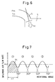
- the cylinder intake air flow rate mc will be explained with reference to FIG. 7 for the case where the internal combustion engine has four cylinders.
- the abscissa is the rotational angle of the crankshaft, while the ordinate is the inflowing airflow rate, i.e., the amount of air actually flowing from the intake pipe part 13' to the combustion chamber 5 per unit time.
- the intake valve 6 for example opens in the order of the #1 cylinder, #3 cylinder, #4 cylinder, and #2 cylinder. Air flows from the intake pipe part 13' to the combustion chamber 5 of each cylinder in accordance with the amount of opening of the intake valve 6 corresponding to each cylinder.
- the change in the flow rate of the air flowing from the intake pipe part 13' into the combustion chamber 5 of each cylinder is as shown by the broken line in FIG. 7.
- the flow rate of the air flowing from the intake pipe part 13' into the combustion chambers 5 of all cylinders combining these is as shown by the solid line in FIG. 7.
- the cylinder air filling amount Mc to the #1 cylinder corresponds to the part shown by hatching in FIG. 7.
- the average of the flow rates of air flowing from the intake pipe part 13' into the combustion chambers 5 of all of the cylinders shown by the solid line is the cylinder intake air flow rate mc and is shown by the dot-chain line in the figure.
- the cylinder intake air flow rate mc shown by the dot-chain line multiplied with the time ⁇ T 180° required for the crankshaft to rotate 180° in the case of four cylinders (that is, in a four-stroke type internal combustion engine, the angle 720° of rotation of the crankshaft in one cycle divided by the number of cylinders) becomes the cylinder air filling amount Mc.
- the cylinder intake air flow rate mc and the cylinder air filling rate K1 can be said to be equivalent values of the cylinder air filling amount Mc, i.e., values corresponding to the cylinder air filling amount Mc. Note that as clear from the above explanation, if multiplying the value b in equation (9) with ⁇ T 180° , the amount of burned gas remaining in a combustion chamber 5 when the exhaust valve 8 is closed can be considered to be obtained.
- the internal combustion engine is controlled as follows. That is, first, the required torque TQr is found based on the amount of accelerator depression, the engine speed, the shift position, and other operating conditions.
- the required torque TQr is found based on a map prepared in advance linking required torques TQr with various operating conditions (that is, a map having, for example, the amount of accelerator depression, engine speed, shift position, etc. as arguments).
- the required cylinder air filling amount Mcr is found based on the required torque TQr.
- equation (2) or equation (3) is used to find the required throttle opening degree ⁇ tr as the opening degree of the throttle valve for realizing the required intake pipe pressure Pmr. That is, at the time of steady state operation, the throttle valve air passage flow rate and the cylinder intake air flow rate match, so equation (11) stands. Further, by finding the throttle opening degree satisfying equation (11), it is possible to find the required throttle opening degree ⁇ tr.
- the required intake pipe pressure Pmr is the value of convergence of the intake pipe pressure at the downstream side of the throttle valve when maintaining the throttle opening degree at the required throttle opening degree ⁇ tr:
- the required throttle opening degree ⁇ tr is set as it is as the target opening degree ⁇ tta (therefore, in the present embodiment, the required intake pipe pressure Pmr, the required cylinder intake air flow rate mcr, and the required cylinder air filling amount Mcr also become as they are the target intake pipe pressure Pmta, the target cylinder intake air flow rate mcta, and the target cylinder air filling amount Mcta).
- the throttle valve 18 that is, the step motor 17
- the required cylinder air filling amount Mcr that is, the target cylinder air filling amount Mcta
- the target fuel injection amount FUta is set in accordance with the target cylinder air filling amount Mcta designed to be realized in the above way.
- the operation of the fuel injector 11 is controlled so that the actual fuel injection amount matches the target fuel injection amount FUta.
- the control of the cylinder air filling amount Mc in the present embodiment is realized by control of the throttle opening degree ⁇ t as explained above, but in actuality, even if the throttle opening degree ⁇ t is made the target opening degree ⁇ tta, a certain time is taken until the cylinder air filling amount Mc (or its equivalent values mc or K1) becomes the target cylinder air filling amount Mcta (or the target value of the equivalent value mc or K1, that is, the target cylinder intake air flow rate mcta or target cylinder air filling rate Klta). That is, the change in the cylinder air filling amount Mc (or its equivalent value mc or K1) has a delay from the change of the throttle opening degree ⁇ t.
- FIG. 8 is a view for showing the response time constant ⁇ taking as an example the change of the cylinder air filling amount Mc.
- ⁇ tb is the throttle opening degree before change
- ⁇ tta is the throttle opening degree after change (that is, the target opening degree)
- t0 is the time of change of the throttle opening degree.
- Mc0 is the cylinder air filling amount when changing the throttle opening degree
- Mcta is the cylinder air filling amount converging when changing the throttle opening degree to the target opening degree ⁇ tta (that is, the target cylinder air filling amount).
- this response time constant ⁇ has previously been found using a map.
- tremendous time is required for actually preparing a map of the response time constant ⁇ . That is, to prepare a map, it is necessary to find the response time constant ⁇ while successively changing the engine speed, the opening timings of the intake and exhaust valves, and other arguments. This work is tremendous. Further, there is the concern that due to the increase in the necessary number of maps or arguments, the map search operations will increase and the control load will increase.
- the response time constant ⁇ is found by calculation by the method explained below.
- the cylinder air filling amount Mc, the cylinder intake air flow rate mc, and the cylinder air filling rate K1 are in proportional relations with each other, so the response time constant ⁇ for any of these values becomes the same and can be found by the following method. That is, in the present embodiment, if considering the change over time of the total gas amount M of the intake pipe part 13', equation (12) is obtained from equation (7) and equation (3), equation (9), etc.
- the response time constant ⁇ to be found becomes equal to the response time constant (63% response time) when the downstream side intake pipe pressure Pm changes from the value Pm0 (start point) when changing the throttle opening degree ⁇ t to the target opening degree ⁇ tta (hereinafter called the "current intake pipe pressure") to the target intake pipe pressure Pmta (convergence point).
- this value can be obtained by finding the response time constant ⁇ satisfying equation (14) obtained from equation (13) if making the time when changing the throttle opening degree ⁇ t to the target opening degree ⁇ tta (more specifically, when finishing changing the throttle opening degree ⁇ t to the target opening degree ⁇ tta) t0.
- Pm0 Pm(t0).
- finding the response time constant ⁇ satisfying equation (14) is synonymous with finding n ⁇ t when the cumulative value of pressure change ⁇ Pm for each discrete time ⁇ t calculated by equation (15) obtained using the discrete time as ⁇ t from equation (13) becomes 0.63 (Pmta-Pm0).
- FIG. 9 is a view of the process of calculation of the response time constant ⁇ by equation (15) or equation (16) replacing the part of mt(t)-mc(t) of equation (15) with ⁇ M(t).
- the ordinate shows the throttle valve air passage flow rate mt and the cylinder intake air flow rate mc, while the abscissa shows the downstream side intake pipe pressure Pm.
- the curve shown by mt is the curve expressed by equation (2) or equation (3), while the line expressed by mc is the line expressed by equation (9).
- the cumulative value of the pressure change ⁇ P (that is, the value at the left side of equation (16)) does not match with 0.63 (Pmta-Pm0). Therefore, more specifically, the n when the cumulative value of the pressure change ⁇ P becomes more than 0.63 (Pmta-Pm0) is found. Then, the value obtained by multiplying the n by the discrete time ⁇ t is found as the response time constant ⁇ . Further, in this method, the calculation can be facilitated by making the atmospheric pressure Pa and the atmospheric temperature Ta constant and also by assuming that the downstream side intake pipe temperature Tm(t) is constant.
- the response time constant ⁇ can be found by the above method, but it is also possible to find it more simply using the method described next. According to this method, it is possible to avoid repeated calculations of equation (15).
- equation (20) and equation (21) can be written as in equation (22) if considering a triangle shown in FIG. 10 similar to FIG. 9, that is, a triangle obtained by connecting the points expressing the throttle valve air passage flow rate mt and the cylinder intake air flow rate mc at the time of the current intake pipe pressure Pm0 and the point where, at the target intake pipe pressure Pmta, the throttle valve air passage flow rate mt and the cylinder intake air flow rate mc match.
- the bottom side of the triangle is mt0-mc0 and the height of the triangle is Pmta-Pm0.
- ⁇ height of triangle bottom side of triangle ⁇ Vm R ⁇ Tm
- the compliance parameters a and b sometimes take two different values (for example, a1, b1 and a2, b2) when the downstream side intake pipe pressure Pm is large and when it is small (this case is shown by the dot-chain line in FIG. 10). Even in such a case, it is possible to find a response time constant ⁇ approximately by equation (20) or equation (21).
- the required throttle opening degree ⁇ tr derived directly from the required torque TQr is used as it is, but in such a case the target opening degree ⁇ tta will fluctuate largely (hunt) with respect to a slight change in the required torque TQr. As a result, the frequency of operation of the throttle valve sometimes increases and has a detrimental effect on the durability of the throttle valve.
- the required throttle opening degree ⁇ tr is found as the throttle opening degree ⁇ t for making the downstream side intake pipe pressure Pm the required intake pipe pressure Pmr so as to make the cylinder intake air flow rate mc the required cylinder intake air flow rate mcr determined in according to the required torque TQr, but in general the effect of a change of the opening degree of the throttle valve on the downstream side intake pipe pressure Pm or the cylinder intake air flow rate mc etc. becomes extremely small in the region where the throttle opening degree ⁇ t is large, that is, in the region where the downstream side intake pipe pressure Pm is large (see FIG. 11).
- the target opening degree ⁇ tta of the throttle valve by the method explained below. That is, with this method, when the required intake pipe pressure Pmr found from the required torque TQr is larger than the predetermined pressure Pmg, it is judged that the possibility of hunting arising is high and in principle a throttle opening degree different from the required throttle opening degree ⁇ tr derived directly from the required torque TQr is set as the target opening degree ⁇ tta. Below, this method will be explained in detail while referring to FIG. 12.
- FIG. 12 shows, at the top, the relationship between the downstream side intake pipe pressure Pm and the cylinder intake air flow rate mc and shows, at the bottom, the relationship between the downstream side intake pipe pressure Pm and the throttle opening degree ⁇ t.
- Pmmax is the maximum value of the downstream side intake pipe pressure Pm, for example, the downstream side intake pipe pressure Pm when the throttle opening degree ⁇ t determined in accordance with the engine speed is full open.
- the atmospheric pressure Pa may be simply used.
- Pmg is the pressure where hunting of the throttle opening degree ⁇ t may easily occur when the downstream side intake pipe pressure Pm exceeds the pressure Pmg and is determined in advance by experiments etc. This predetermined pressure Pmg may be made for example 0.95 Pmmax.
- the throttle opening degree found in accordance with the required cylinder intake air flow rate mcr derived from the required torque TQr becomes the required throttle opening degree ⁇ tr for realizing the required intake pipe pressure Pmr derived from the required torque TQr.
- this required throttle opening degree ⁇ tr is made the target opening degree ⁇ tta.
- the required intake pipe pressure Pmr becomes larger than the predetermined pressure Pmg.
- the required throttle opening degree ⁇ tr is made the target opening degree ⁇ tta as it is, so the possibility of hunting of the throttle opening degree ⁇ t is high. Therefore, with this method, in this case, the throttle opening degree ⁇ ts corresponding to the predetermined pressure Pmg is found as the corrected target opening degree and this is set as the target opening degree ⁇ tta.
- the realized cylinder intake air flow rate mc becomes the mcs in FIG. 12.
- the corrected target opening degree ⁇ ts found in the above way plus the correction value ⁇ that is, the opening degree ⁇ te
- This correction value ⁇ is set corresponding to the tolerance of the throttle opening degree sensor 43 and the deposits on the throttle valve etc. and is determined based on at least the engine speed.
- this correction value ⁇ it is possible to prevent the actual throttle opening area from becoming smaller due to the tolerance of the throttle opening degree sensor 43 and the deposits on the throttle valve etc. and as a result the target opening degree ⁇ tta being set excessively small.
- the required intake pipe pressure Pmr becomes larger than the predetermined pressure Pmg, in certain cases, it is also possible to set the required throttle opening degree ⁇ tr as it is as the target opening degree ⁇ tta. That is, for example, when the generation of a large output is given priority over suppression of hunting, it is required to set the required throttle opening degree ⁇ tr as it is as the target opening degree ⁇ tta and the required cylinder intake air flow rate mcr is realized. By doing this, it is possible to realize control giving priority to operation matching the requirements more than suppressing hunting.
- the throttle valve air passage flow rate mt etc. were calculated using the intake pipe pressure at the upstream side of the throttle valve 18 (hereinafter referred to as the "upstream side intake pipe pressure") as the atmospheric pressure Pa but, in general, the actual upstream side intake pipe pressure becomes a pressure lower than the atmospheric pressure Pa during engine operation since there is pressure loss at the upstream side of the throttle valve in an engine intake system.
- the upstream side intake pipe pressure the intake pipe pressure at the upstream side of the throttle valve 18
- the actual upstream side intake pipe pressure becomes a pressure lower than the atmospheric pressure Pa during engine operation since there is pressure loss at the upstream side of the throttle valve in an engine intake system.
- the upstream side intake pipe pressure Pac may also be detected by providing a pressure sensor directly upstream of the throttle valve 18, but it may also be calculated without using a pressure sensor. That is, the difference between the atmospheric pressure Pa and the upstream side intake pipe pressure Pac can be expressed by equation (23) by Bernoulli's theorem.
- ⁇ is the atmospheric density
- v is the velocity (current) of air passing through the air cleaner 16
- Ga is the flow rate of air passing through the air cleaner 16
- k is the proportional coefficient of v and Ga.
- Equation (25) can be modified as in equation (26) showing the upstream side intake pipe pressure Pac.
- the flow rate Ga can be detected by an air flow meter when an air flow meter is provided right at the downstream side of the air cleaner 16.
- the pressure correction coefficient ekpa can be set by the detected atmospheric pressure Pa
- the temperature correction coefficient ektha can be set by the detected atmospheric temperature Ta.
- Pac Pa - f(Ga) ekpa ⁇ ektha
- the flow rate Ga of the air passing through the air cleaner 16 can be considered the throttle valve air passage flow rate mt and therefore equation (26) can be modified as in equation (27):
- Pac Pa - f(mt) ekpa ⁇ ektha
- a control device of an internal combustion engine designed to find a response time constant of a cylinder air filling amount or its equivalent value by a simpler method.
- the control device comprises means for setting the target opening degree, means for finding a target intake pipe pressure, means for finding a current intake pipe pressure, means for finding a throttle valve air passage flow rate, and means for finding a cylinder intake air flow rate and calculating the response time constant based on the target intake pipe pressure, the current intake pipe pressure, the throttle valve air passage flow rate, and the cylinder intake air flow rate.
Landscapes
- Engineering & Computer Science (AREA)
- Chemical & Material Sciences (AREA)
- Combustion & Propulsion (AREA)
- Mechanical Engineering (AREA)
- General Engineering & Computer Science (AREA)
- Combined Controls Of Internal Combustion Engines (AREA)
- Electrical Control Of Air Or Fuel Supplied To Internal-Combustion Engine (AREA)
Applications Claiming Priority (2)
| Application Number | Priority Date | Filing Date | Title |
|---|---|---|---|
| JP2003301356 | 2003-08-26 | ||
| JP2003301356A JP4207718B2 (ja) | 2003-08-26 | 2003-08-26 | 内燃機関の制御装置 |
Publications (3)
| Publication Number | Publication Date |
|---|---|
| EP1510677A2 true EP1510677A2 (de) | 2005-03-02 |
| EP1510677A3 EP1510677A3 (de) | 2010-11-03 |
| EP1510677B1 EP1510677B1 (de) | 2011-11-30 |
Family
ID=34101169
Family Applications (1)
| Application Number | Title | Priority Date | Filing Date |
|---|---|---|---|
| EP04020186A Expired - Lifetime EP1510677B1 (de) | 2003-08-26 | 2004-08-25 | Steuervorrichtung für eine Brennkraftmaschine |
Country Status (3)
| Country | Link |
|---|---|
| US (1) | US6986337B2 (de) |
| EP (1) | EP1510677B1 (de) |
| JP (1) | JP4207718B2 (de) |
Cited By (4)
| Publication number | Priority date | Publication date | Assignee | Title |
|---|---|---|---|---|
| EP1650417A3 (de) * | 2004-10-19 | 2008-02-20 | Toyota Jidosha Kabushiki Kaisha | Vorrichtung zur Regelung einer Brennkraftmaschine |
| WO2018182494A1 (en) * | 2017-03-31 | 2018-10-04 | Scania Cv Ab | Control of an automated clutch and of an engine torque |
| EP3540199A1 (de) * | 2018-03-16 | 2019-09-18 | Toyota Jidosha Kabushiki Kaisha | Steuergerät und steuerungsverfahren für verbrennungsmotor |
| EP3643907A1 (de) * | 2018-10-24 | 2020-04-29 | Toyota Jidosha Kabushiki Kaisha | Drosselklappensteuerung und drosselklappensteuerverfahren |
Families Citing this family (16)
| Publication number | Priority date | Publication date | Assignee | Title |
|---|---|---|---|---|
| JP3985746B2 (ja) * | 2003-08-26 | 2007-10-03 | トヨタ自動車株式会社 | 内燃機関の制御装置 |
| JP4114574B2 (ja) * | 2003-08-26 | 2008-07-09 | トヨタ自動車株式会社 | 内燃機関の吸気量制御装置及び吸気量制御方法 |
| US7613958B2 (en) | 2004-01-12 | 2009-11-03 | Hewlett-Packard Development Company, L.P. | Error detection in a system having coupled channels |
| US7672222B2 (en) * | 2004-01-12 | 2010-03-02 | Hewlett-Packard Development Company, L.P. | Link failures |
| US7606253B2 (en) * | 2004-01-12 | 2009-10-20 | Hewlett-Packard Development Company, L.P. | Successful transactions |
| US7721159B2 (en) * | 2005-02-11 | 2010-05-18 | Hewlett-Packard Development Company, L.P. | Passing debug information |
| US7624213B2 (en) * | 2005-02-11 | 2009-11-24 | Hewlett-Packard Development Company, L.P. | Passing identification information |
| US7380447B2 (en) * | 2006-06-10 | 2008-06-03 | Ford Global Technologies. Llc | Method and system for transient airflow compensation in an internal combustion engine |
| JP2008133767A (ja) * | 2006-11-28 | 2008-06-12 | Toyota Motor Corp | モデルベース開発におけるモデル簡易化手法 |
| JP4941069B2 (ja) * | 2007-04-17 | 2012-05-30 | 日産自動車株式会社 | 内燃機関の吸気制御装置 |
| JP2009203867A (ja) * | 2008-02-27 | 2009-09-10 | Honda Motor Co Ltd | 内燃機関の燃料噴射量を制御するための装置 |
| DE102013113167A1 (de) * | 2013-11-28 | 2015-05-28 | Daimler Ag | Verfahren und Vorrichtung zum Betreiben eines Verbrennungsmotors |
| IT201800009528A1 (it) * | 2018-10-17 | 2020-04-17 | Fpt Ind Spa | Dispositivo di controllo di una valvola a farfalla di un motore a combustione interna e motore a combustione interna comprendente detto dispositivo |
| CN113418706B (zh) * | 2021-05-31 | 2022-11-11 | 中国环境科学研究院 | 发动机平均摩擦损失压力获取方法及计算机产品 |
| JP7759087B2 (ja) * | 2021-09-07 | 2025-10-23 | 株式会社ニッキ | エンジンの燃料噴射制御方法および装置 |
| JP7717180B2 (ja) * | 2021-11-22 | 2025-08-01 | Astemo株式会社 | 内燃機関の制御装置 |
Family Cites Families (11)
| Publication number | Priority date | Publication date | Assignee | Title |
|---|---|---|---|---|
| EP0594114B1 (de) * | 1992-10-19 | 1999-12-15 | Honda Giken Kogyo Kabushiki Kaisha | Regelungssystem für die Brennstoffdosierung eines Innenverbrennungsmotors |
| JP3330234B2 (ja) * | 1994-07-29 | 2002-09-30 | 本田技研工業株式会社 | 内燃機関の燃料噴射制御装置 |
| JP2000097086A (ja) * | 1998-09-18 | 2000-04-04 | Hitachi Ltd | エンジンの吸入空気流量制御方法、制御装置および出力制御方法 |
| JP4075233B2 (ja) | 1999-07-29 | 2008-04-16 | トヨタ自動車株式会社 | 内燃機関の吸入空気量予測装置 |
| US6460409B1 (en) * | 2000-05-13 | 2002-10-08 | Ford Global Technologies, Inc. | Feed-forward observer-based control for estimating cylinder air charge |
| US6363316B1 (en) * | 2000-05-13 | 2002-03-26 | Ford Global Technologies, Inc. | Cylinder air charge estimation using observer-based adaptive control |
| JP2002130042A (ja) * | 2000-10-19 | 2002-05-09 | Denso Corp | 内燃機関の筒内充填空気量検出装置 |
| JP2002201998A (ja) * | 2000-11-06 | 2002-07-19 | Denso Corp | 内燃機関の制御装置 |
| JP2002303177A (ja) * | 2001-04-04 | 2002-10-18 | Denso Corp | 内燃機関の電子スロットル制御装置 |
| JP2002332884A (ja) | 2001-05-01 | 2002-11-22 | Denso Corp | 内燃機関の制御装置 |
| JP3900064B2 (ja) * | 2002-10-30 | 2007-04-04 | トヨタ自動車株式会社 | 内燃機関の吸入空気量推定装置 |
-
2003
- 2003-08-26 JP JP2003301356A patent/JP4207718B2/ja not_active Expired - Fee Related
-
2004
- 2004-08-20 US US10/922,102 patent/US6986337B2/en not_active Expired - Lifetime
- 2004-08-25 EP EP04020186A patent/EP1510677B1/de not_active Expired - Lifetime
Cited By (7)
| Publication number | Priority date | Publication date | Assignee | Title |
|---|---|---|---|---|
| EP1650417A3 (de) * | 2004-10-19 | 2008-02-20 | Toyota Jidosha Kabushiki Kaisha | Vorrichtung zur Regelung einer Brennkraftmaschine |
| WO2018182494A1 (en) * | 2017-03-31 | 2018-10-04 | Scania Cv Ab | Control of an automated clutch and of an engine torque |
| EP3540199A1 (de) * | 2018-03-16 | 2019-09-18 | Toyota Jidosha Kabushiki Kaisha | Steuergerät und steuerungsverfahren für verbrennungsmotor |
| CN110273763A (zh) * | 2018-03-16 | 2019-09-24 | 丰田自动车株式会社 | 用于内燃机的控制器和控制方法 |
| US10738719B2 (en) | 2018-03-16 | 2020-08-11 | Toyota Jidosha Kabushiki Kaisha | Controller and control method for internal combustion engine |
| CN110273763B (zh) * | 2018-03-16 | 2022-02-18 | 丰田自动车株式会社 | 用于内燃机的控制器和控制方法 |
| EP3643907A1 (de) * | 2018-10-24 | 2020-04-29 | Toyota Jidosha Kabushiki Kaisha | Drosselklappensteuerung und drosselklappensteuerverfahren |
Also Published As
| Publication number | Publication date |
|---|---|
| JP2005069134A (ja) | 2005-03-17 |
| EP1510677A3 (de) | 2010-11-03 |
| EP1510677B1 (de) | 2011-11-30 |
| US20050081823A1 (en) | 2005-04-21 |
| JP4207718B2 (ja) | 2009-01-14 |
| US6986337B2 (en) | 2006-01-17 |
Similar Documents
| Publication | Publication Date | Title |
|---|---|---|
| EP1510677B1 (de) | Steuervorrichtung für eine Brennkraftmaschine | |
| JP4352830B2 (ja) | 内燃機関の制御装置 | |
| EP1662118B1 (de) | Vorrichtung und verfahren zur steuerung der saugluftmenge in einem verbrennungsmotor | |
| EP1662128B1 (de) | Steuerungssystem für einen verbrennungsmotor | |
| EP1837510B1 (de) | Steuerung von verbrennungsmotoren | |
| US7703436B2 (en) | Control device of internal combustion engine | |
| JP5994465B2 (ja) | エンジンの制御装置 | |
| JP4254389B2 (ja) | 内燃機関の制御装置 | |
| JP4241560B2 (ja) | 内燃機関の吸入空気量推定装置 | |
| JP4032957B2 (ja) | 吸気管内圧力算出装置及び吸気管内温度算出装置 | |
| JP3897690B2 (ja) | 制御弁通過ガス流量算出装置 | |
| JP4172359B2 (ja) | 内燃機関の制御装置 | |
| JP4737191B2 (ja) | 吸気通路容積算出装置 | |
| JP2006057516A (ja) | 内燃機関の制御装置 | |
| JP2009085227A (ja) | 内燃機関の制御装置 | |
| JP3945510B2 (ja) | 内燃機関の筒内充填空気量推定装置 | |
| JP4420106B2 (ja) | スロットル弁通過空気流量算出装置 | |
| JP2006077620A (ja) | 内燃機関の制御装置 |
Legal Events
| Date | Code | Title | Description |
|---|---|---|---|
| PUAI | Public reference made under article 153(3) epc to a published international application that has entered the european phase |
Free format text: ORIGINAL CODE: 0009012 |
|
| 17P | Request for examination filed |
Effective date: 20040825 |
|
| AK | Designated contracting states |
Kind code of ref document: A2 Designated state(s): AT BE BG CH CY CZ DE DK EE ES FI FR GB GR HU IE IT LI LU MC NL PL PT RO SE SI SK TR |
|
| AX | Request for extension of the european patent |
Extension state: AL HR LT LV MK |
|
| PUAL | Search report despatched |
Free format text: ORIGINAL CODE: 0009013 |
|
| AK | Designated contracting states |
Kind code of ref document: A3 Designated state(s): AT BE BG CH CY CZ DE DK EE ES FI FR GB GR HU IE IT LI LU MC NL PL PT RO SE SI SK TR |
|
| AX | Request for extension of the european patent |
Extension state: AL HR LT LV MK |
|
| RIC1 | Information provided on ipc code assigned before grant |
Ipc: F02D 11/10 20060101AFI20041203BHEP Ipc: F02D 41/00 20060101ALI20100928BHEP Ipc: F02D 41/18 20060101ALI20100928BHEP |
|
| RIC1 | Information provided on ipc code assigned before grant |
Ipc: F02D 41/00 20060101ALI20110330BHEP Ipc: F02D 41/18 20060101ALI20110330BHEP Ipc: F02D 11/10 20060101AFI20110330BHEP |
|
| GRAP | Despatch of communication of intention to grant a patent |
Free format text: ORIGINAL CODE: EPIDOSNIGR1 |
|
| GRAC | Information related to communication of intention to grant a patent modified |
Free format text: ORIGINAL CODE: EPIDOSCIGR1 |
|
| AKX | Designation fees paid |
Designated state(s): DE FR |
|
| GRAS | Grant fee paid |
Free format text: ORIGINAL CODE: EPIDOSNIGR3 |
|
| GRAA | (expected) grant |
Free format text: ORIGINAL CODE: 0009210 |
|
| AK | Designated contracting states |
Kind code of ref document: B1 Designated state(s): DE FR |
|
| RIN1 | Information on inventor provided before grant (corrected) |
Inventor name: MUTOU, HARUHUMI |
|
| REG | Reference to a national code |
Ref country code: DE Ref legal event code: R096 Ref document number: 602004035478 Country of ref document: DE Effective date: 20120209 |
|
| PLBE | No opposition filed within time limit |
Free format text: ORIGINAL CODE: 0009261 |
|
| STAA | Information on the status of an ep patent application or granted ep patent |
Free format text: STATUS: NO OPPOSITION FILED WITHIN TIME LIMIT |
|
| 26N | No opposition filed |
Effective date: 20120831 |
|
| REG | Reference to a national code |
Ref country code: DE Ref legal event code: R097 Ref document number: 602004035478 Country of ref document: DE Effective date: 20120831 |
|
| REG | Reference to a national code |
Ref country code: DE Ref legal event code: R084 Ref document number: 602004035478 Country of ref document: DE Effective date: 20130522 |
|
| REG | Reference to a national code |
Ref country code: FR Ref legal event code: PLFP Year of fee payment: 13 |
|
| REG | Reference to a national code |
Ref country code: FR Ref legal event code: PLFP Year of fee payment: 14 |
|
| REG | Reference to a national code |
Ref country code: FR Ref legal event code: PLFP Year of fee payment: 15 |
|
| PGFP | Annual fee paid to national office [announced via postgrant information from national office to epo] |
Ref country code: FR Payment date: 20210715 Year of fee payment: 18 |
|
| PGFP | Annual fee paid to national office [announced via postgrant information from national office to epo] |
Ref country code: DE Payment date: 20210713 Year of fee payment: 18 |
|
| REG | Reference to a national code |
Ref country code: DE Ref legal event code: R119 Ref document number: 602004035478 Country of ref document: DE |
|
| PG25 | Lapsed in a contracting state [announced via postgrant information from national office to epo] |
Ref country code: FR Free format text: LAPSE BECAUSE OF NON-PAYMENT OF DUE FEES Effective date: 20220831 Ref country code: DE Free format text: LAPSE BECAUSE OF NON-PAYMENT OF DUE FEES Effective date: 20230301 |