EP1510617A2 - Blähkörper und Vorrichtung zum Trocknen und/oder Glätten von Kleidungsstücken - Google Patents
Blähkörper und Vorrichtung zum Trocknen und/oder Glätten von Kleidungsstücken Download PDFInfo
- Publication number
- EP1510617A2 EP1510617A2 EP04020304A EP04020304A EP1510617A2 EP 1510617 A2 EP1510617 A2 EP 1510617A2 EP 04020304 A EP04020304 A EP 04020304A EP 04020304 A EP04020304 A EP 04020304A EP 1510617 A2 EP1510617 A2 EP 1510617A2
- Authority
- EP
- European Patent Office
- Prior art keywords
- shell
- inflatable body
- sheath
- length
- connecting line
- Prior art date
- Legal status (The legal status is an assumption and is not a legal conclusion. Google has not performed a legal analysis and makes no representation as to the accuracy of the status listed.)
- Withdrawn
Links
Images

Classifications
-
- D—TEXTILES; PAPER
- D06—TREATMENT OF TEXTILES OR THE LIKE; LAUNDERING; FLEXIBLE MATERIALS NOT OTHERWISE PROVIDED FOR
- D06F—LAUNDERING, DRYING, IRONING, PRESSING OR FOLDING TEXTILE ARTICLES
- D06F73/00—Apparatus for smoothing or removing creases from garments or other textile articles by formers, cores, stretchers, or internal frames, with the application of heat or steam
Definitions
- the invention relates to a swelling body and a device for drying and / or smoothing of clothes.
- a hanger doll in which on the inside of the Inflatable bag at least one pulling device for adjusting the circumference of the ironing manikin is provided in at least one level.
- the sheaths in which the tension elements are guided can be sewn to the inflatable bag or from a circumferential fold of the inflatable sack are sewn.
- fuselage trains raises the problem of leading the free ones Ends of the tension element from the shell.
- the cut parts of the Inflated body usually by seams that are perpendicular to the length of the shell, sewn together.
- For a maximum Einschnür für by the fuselage to obtain the envelope therefore extends to the edge of the section that this wearing.
- the leading out of the ends of the tension element from the shell can at this Edge, which is closed by the vertical seam, usually only be ensured by providing eyelets in the shell.
- eyelets entails the disadvantage that they hinder the attachment of the sheath to the cut portion of the body portion, the creation of the sheath by sewing a pleat, and the sewing of this cut portion of the body portion with other cut pieces.
- too small eyelets it may happen that the tension element in this tilted or hooked and a contraction of the fuselage is no longer possible or at least difficult.
- larger eyelets then the dimension of the hull of the hull train must be increased, which leads to a reduction of the effective catchment area of the fuselage train, especially in the interior of the hull trains.
- the invention is based on the finding that this object can be achieved by the shape of the hull of the hull is chosen so that through the material of Case, in particular by the edge of the shell, an outlet opening for a tension element the trunk is formed, which extends over part of the length of the shell.
- a swelling body for drying and / or smoothing garments having at least one body portion at least one hull train is provided for setting a defined hull circumference is, which has a shell in which a tension element is guided, wherein the sheath along a connecting line is connected to a sectional part of the inflatable body and the length the envelope is smaller over part of the circumference of the envelope than at the connecting line.
- the part of the fuselage, in which the Tensile element is guided As a shell is referred to in the sense of this invention, the part of the fuselage, in which the Tensile element is guided.
- This shell preferably has the shape of a tube.
- the length of the shell in the sense of this invention is the dimension of the shell in the circumferential direction understood the trunk section.
- the length of the shell can be one single Hose or be formed from several hose parts.
- the connecting line of the envelope is the line along which the envelope on the Sewed on the cut part or sewn to form the envelope a fold from the cut part is.
- the Edge of the shell has an outlet opening for the tension element, which is guided in the fuselage is to be formed. Additional parts, such as eyelets, can thus be dispensed with become. As a result, the production of the inflatable body is facilitated because the processing of the hull and the section which carries the haulage, not hindered becomes. Since the length of the sheath over a portion of the circumference is less than at the Connecting line, an opening is formed on the shell, which extends over part of the Length of the shell extends. Thus, it can also provide a seam at the edge of the Envelope, in a direction substantially perpendicular to the length of the envelope, do not come to a closure of the opening. Such a vertical seam becomes, for example for sewing the cut part, which carries the envelope, with another Used section.
- the length of the sheath over the circumference of the connecting line continuously decreases up to a minimum length and from this again continuously up to the Length of connecting line to.
- Particularly preferred is the smallest length of the connecting line on the circumference of the shell opposite.
- the seam is not weakened and at the same time an opening is obtained, which is formed by the entire edge of the shell becomes. This opening is therefore large enough to tilt the tension element, which is led out of the shell to avoid.
- the continuous weight loss the length advantageous for manufacturing reasons.
- material for the shell is in the Usually a substance, e.g. a woven fabric, used. With a continuous decrease and increase in length can cause fraying of the edge even with such a fabric the envelope are largely avoided.
- the shell is designed so that at both ends of the shell the end of the smallest length is offset from the end of the connecting line. This means, that openings are formed at both ends of the shell. A tension element in this Case is guided, thus can at both ends of the shell with its free ends escape.
- the envelope is formed by several tube parts, then the two envelope parts, which form the ends of the shell, a shortening of the length according to the invention on, however, the end of the shorter length only on one side opposite to the End of the connecting line is offset. On the other side of this section are the End of the lesser length and the end of the connecting line together.
- further cutting parts which is Length of the shell over the circumference preferably constant.
- the hull of the hull is on the inside of the hull section provided the inflatable body.
- the advantages, which are achieved by the inventive shape of the shell be used particularly. Namely, one over the entire circumference of the body portion of the inflatable body extending hull train with a shell according to the invention at least one Part of its circumference has a shorter length, so used, the two ends the envelope can be guided close to one another at the connecting line, without that the outlet opening closed at one end of the shell by the other end of the shell becomes. This effect would occur if the sheath through a hose with a constant Length over its circumference would be formed.
- the shell through a hose form, which is sewn to a cut portion of the inflatable body it is preferably the shell of the hull train to form by a fold in a section of the inflatable body.
- the Outlet openings are also characterized by the different length of the shell formed, wherein preferably the cut part, placed on the fold for the hull train is, in the region of the fold having a recess on the edge. This can the shape of the shell already in the blank of the cut portion on which the shell provided is to be set. A separate cutting of the shell can thus be omitted.
- the recess has an arc shape at the edge of the cut part.
- two extend initially from the edge of the cut part essentially parallel cutting lines, which then pass into the arc shape.
- a separate sectional part with an outlet for a tension element.
- the tension elements can in this case namely from the shell of the fuselage guided and placed to the outlet in the separate section from where from this can be brought from the inflatable body.
- the other cut pieces that make up the hull section can be dimensioned and materials are adapted to the respective requirements, since the outlet for the traction means, which may for example be a cord, in one from the remainder of the fuselage section, especially from the cut section that houses the fuselage trains carries, separate cutting part is provided.
- the outlet for example can be reinforced by eyelets, not hindering in the production of the trunk section act or accidentally closed because the cut part, this carries, incorporated only after completion of the other body section in this, in particular can be sewn into this.
- the invention relates to a device for drying and / or smoothing garments comprising a body of the invention.
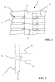
- FIG. 1 shows an embodiment of an inflatable body 1 according to the invention.
- This has a body portion 11 and sleeve portions 17.
- the fuselage section 11 are provided on the inside of hulls 2 of fuselages 12, which here through the externally visible connecting lines 21, which are formed by seams, indicated are.
- each tension elements 13 are guided. The tension elements 13 extend over the entire circumference of the body portion 11th
- a region 14 is provided over substantially the entire length of the body portion 11, the drying of the button placket of a personallyspannenden to the inflatable body Shirt serves.
- This area 14 is formed by a material with high air permeability.
- the sheaths 2 of the fuselage trains 12 are not provided at this area.
- the Tension elements 13 are thus guided freely in this area 14 in the interior of the inflatable body 1.
- a separate cut part 15 is arranged Adjacent to the region 14 is on one side in the lower region of the fuselage section 11, a separate cut part 15 is arranged.
- This section 15 extends along the area 14 and ends at a height which is slightly above the uppermost shell 2.
- eyelets 16 are provided in the separate section 15 .
- the eyelets 16 are at a distance to each other, which corresponds to the distance between the individual cases 2.
- the tension elements 13 may fixation elements, such as terminals or the like provided be to set a certain circumference of the body portion 11 of the inflatable body 1 to be able to.
- FIG. 2 shows a schematic detail view of the fuselage trains 12 from the interior of the inflatable body 1 shown.
- the entire sheaths 2 extend over the entire circumference of the Fuselage section and are not only on the area 14 and the separate interface part 15 intended.
- the casings 2 are thus set in the illustrated embodiment a part provided at the right front cut part, a part that abuts the spine cut part is provided and a part which is on the left front Intersection is provided together.
- the sheaths 2 are formed in the illustrated embodiment by folding, by means of a seam 21 are sewn from a cut portion of the inflatable body 1.
- the part of the shell 2, which has the largest length, here is the part where the seam 21 is provided.
- an opening is made at each end of the sheaths 2 is formed exclusively by the edge of the material of the shell 2. The opening extends over the entire circumference of the shell 2.
- the tension elements 13 can escape and, for example, to the Eyelets 16 are guided in the separate interface part 15.
- FIG. 3 shows a part of a sectional part of the inflatable body from which a shell 2 for the fuselage 12 can be formed and at the same time as a cutting part for the front can serve the inflatable body.
- a recess 31 provided at the edge 3 of the cut part. This recess is from the edge 3 of initially by two in formed essentially parallel to each other cutting lines and then goes into one Bow over. The lowest point of the recess 31 lies in the middle of the recess 31st
- the substantially parallel lines of intersection of the recess 31 extend to a depth of the recess 31 at which a seam 18 for sewing the Can be provided with another cutting part cut part. This route, about which extend the parallel cutting lines, thus corresponds to the seam allowance.
- the invention is not limited to the illustrated embodiment. That's the way it is, for example also possible the recesses at the edges of the cut part to form the envelope in a substantially wedge shape, i. through two straight lines, one on top of the other to run, to design.
- the number of fuselage trains is not limited to the three fuselages shown.
- the hulls of the fuselage trains can also be provided on the inflatable body be that they extend over the entire circumference of the fuselage section. This is on cut parts, such as the separate cutting part 15 or middle section 14, omitted.
- the ends of the sheaths from which the tension elements emerge can also be located in the rear of the fuselage section, or located on the side of the fuselage section.
- the difference in the length of the sheath from the shortest length to the length of the connecting line for forming the outlet opening for the tension element is chosen so that also after the sewing of the cut parts of the inflatable body, the outlet opening is large enough, to easily guide the tension element out of the fuselage.
- the present invention thus provides a swelling body which is easy to manufacture is.
- the hulls for fuselage can here already at the cutting of a Cutting part are defined in terms of their shape.
- the cut part so cut can easily processed, in particular sewn, without that the outlet openings for Tensile elements are closed, or weakened connecting seams between cut parts become.
Landscapes
- Engineering & Computer Science (AREA)
- Textile Engineering (AREA)
- Treatment Of Fiber Materials (AREA)
- Professional, Industrial, Or Sporting Protective Garments (AREA)
- Drying Of Solid Materials (AREA)
Abstract
Description
Es ist daher Aufgabe der vorliegenden Erfindung einen Blähkörper und eine Vorrichtung zum Bügeln und/oder Trocknen von Kleidungsstücken zu schaffen, die einfach herzustellen sind und bei denen ein Zugelement aus der Hülle eines Rumpfzuges geführt werden kann, ohne ein Verkanten oder Verhaken des Zugelementes befürchten zu müssen. Weiterhin soll die Funktionsfähigkeit des Rumpfzuges nicht beeinträchtigt werden.
Claims (9)
- Blähkörper zum Trocknen und/oder Glätten von Kleidungsstücken, der zumindest einen Rumpfabschnitt (11) aufweist, an dem zur Einstellung eines definierten Rumpfumfangs mindestens ein Rumpfzug (12) vorgesehen ist, der eine Hülle (2) aufweist, in der ein Zugelement (13) geführt ist, wobei die Hülle (2) entlang einer Verbindungslinie (21) mit einem Schnittteil des Blähkörpers (1) verbunden ist und die Länge der Hülle (2) über einen Teil des Umfangs der Hülle (2) geringer ist als an der Verbindungslinie (21).
- Blähkörper nach Anspruch 1, dadurch gekennzeichnet, dass die Länge der Hülle (2) über den Umfang der Hülle (2) von der Verbindungslinie (21) kontinuierlich bis zu einer geringsten Länge abnimmt und von dieser wieder kontinuierlich bis zu der Verbindungslinie (21) zunimmt.
- Blähkörper nach einem der Ansprüche 1 oder 2, dadurch gekennzeichnet, dass an beiden Enden der Hülle (2) jeweils das Ende der geringsten Länge gegenüber dem Ende der Verbindungslinie (21) versetzt ist.
- Blähkörper nach einem der Ansprüche 1 bis 3, dadurch gekennzeichnet, dass die Hülle (2) des Rumpfzuges (12) an der Innenseite des Rumpfabschnitts (11) des Blähkörpers (1) vorgesehen ist.
- Blähkörper nach einem der Ansprüche 1 bis 4, dadurch gekennzeichnet, dass die Hülle (2) des Rumpfzuges (21) durch eine Falte in einem Schnittteil des Blähkörpers (1) gebildet wird.
- Blähkörper nach Anspruch 5, dadurch gekennzeichnet, dass das Schnittteil, an dem die Falte für den Rumpfzug (12) gelegt wird, in dem Bereich der Falte eine Ausnehmung (31) an der Kante (3) aufweist.
- Blähkörper nach Anspruch 6, dadurch gekennzeichnet, dass die Ausnehmung (31) eine Bogenform aufweist.
- Blähkörper nach einem der Ansprüche 1 bis 7, dadurch gekennzeichnet, dass angrenzend an das Schnittteil, das ein Ende der Hülle (2) trägt, ein separates Schnittteil (15) mit einem Auslass (16) für ein Zugelement (13) angeordnet ist.
- Vorrichtung zum Trocknen und/oder Glätten von Kleidungsstücken, dadurch gekennzeichnet, dass diese einen Blähkörper gemäß einem der Ansprüche 1 bis 8 aufweist.
Applications Claiming Priority (2)
| Application Number | Priority Date | Filing Date | Title |
|---|---|---|---|
| DE2003139720 DE10339720A1 (de) | 2003-08-28 | 2003-08-28 | Blähkörper und Vorrichtung zum Trocknen und/oder Glätten von Kleidungsstücken |
| DE10339720 | 2003-08-28 |
Publications (2)
| Publication Number | Publication Date |
|---|---|
| EP1510617A2 true EP1510617A2 (de) | 2005-03-02 |
| EP1510617A3 EP1510617A3 (de) | 2009-05-27 |
Family
ID=34089243
Family Applications (1)
| Application Number | Title | Priority Date | Filing Date |
|---|---|---|---|
| EP04020304A Withdrawn EP1510617A3 (de) | 2003-08-28 | 2004-08-26 | Blähkörper und Vorrichtung zum Trocknen und/oder Glätten von Kleidungsstücken |
Country Status (2)
| Country | Link |
|---|---|
| EP (1) | EP1510617A3 (de) |
| DE (1) | DE10339720A1 (de) |
Cited By (1)
| Publication number | Priority date | Publication date | Assignee | Title |
|---|---|---|---|---|
| EP1510616A3 (de) * | 2003-08-28 | 2009-05-27 | BSH Bosch und Siemens Hausgeräte GmbH | Blähkörper und Vorrichtung zum Trocknen und/oder Glätten von Kleidungsstücken |
Family Cites Families (11)
| Publication number | Priority date | Publication date | Assignee | Title |
|---|---|---|---|---|
| GB866855A (en) * | 1958-05-01 | 1961-05-03 | Wichita Prec Tool Co Inc | Bag structure for garment finishing machines |
| US3058635A (en) * | 1959-06-15 | 1962-10-16 | Wm Cissell Mfg Company | Garment finisher shoulder adjusting means |
| US3396881A (en) * | 1966-06-27 | 1968-08-13 | Aloi Alfred | Garment shaping bag with resilient inserts |
| US3385485A (en) * | 1967-02-16 | 1968-05-28 | Aloi Alfred | Garment finishing machine with fluid control casing and mesh type bag |
| US3429489A (en) * | 1967-07-05 | 1969-02-25 | W M Cissell Mfg Co | Form finisher and bag for use therewith |
| US3883896A (en) * | 1972-09-29 | 1975-05-20 | Dona G Cain | Adjustable length garment |
| DE10058744A1 (de) * | 2000-11-27 | 2002-05-29 | Bsh Bosch Siemens Hausgeraete | Verfahren und Vorrichtung zum Bügeln von Kleidungsstücken |
| DE20023274U1 (de) * | 2000-11-27 | 2003-08-07 | BSH Bosch und Siemens Hausgeräte GmbH, 81669 München | Vorrichtung zum Bügeln von Kleidungsstücken |
| DE10108648A1 (de) * | 2001-01-29 | 2002-08-01 | Bsh Bosch Siemens Hausgeraete | Vorrichtung zum Glätten von Hemden |
| DE10260148A1 (de) * | 2002-12-20 | 2004-07-01 | BSH Bosch und Siemens Hausgeräte GmbH | Verfahren und Vorrichtung zum Bügeln von Kleidungsstücken |
| DE10339726A1 (de) * | 2003-08-28 | 2005-03-17 | BSH Bosch und Siemens Hausgeräte GmbH | Blähkörper und Vorrichtung zum Trocknen und/oder Glätten von Kleidungsstücken |
-
2003
- 2003-08-28 DE DE2003139720 patent/DE10339720A1/de not_active Withdrawn
-
2004
- 2004-08-26 EP EP04020304A patent/EP1510617A3/de not_active Withdrawn
Cited By (1)
| Publication number | Priority date | Publication date | Assignee | Title |
|---|---|---|---|---|
| EP1510616A3 (de) * | 2003-08-28 | 2009-05-27 | BSH Bosch und Siemens Hausgeräte GmbH | Blähkörper und Vorrichtung zum Trocknen und/oder Glätten von Kleidungsstücken |
Also Published As
| Publication number | Publication date |
|---|---|
| DE10339720A1 (de) | 2005-03-24 |
| EP1510617A3 (de) | 2009-05-27 |
Similar Documents
| Publication | Publication Date | Title |
|---|---|---|
| DE10060667B4 (de) | Dreidimensionale Airbags für Kraftfahrzeuge | |
| WO1991000834A1 (de) | Aufblasbarer folienbeutel, insbesondere für verpackungszwecke | |
| DE1785428C3 (de) | Einteiliger Kinderschlafanzug und Verfahren zu seiner Herstellung | |
| EP1278901B1 (de) | Vorrichtung zur herstellung von mindestens zwei stülpbaren schlauchartigen gurtbändern | |
| DE2050143A1 (de) | Beinkleid, Verfahren zur Herstellung desselben und Vorrichtung zum Durchfuhren des Verfahrens | |
| DE69401496T2 (de) | Vorrichtung für das anziehen therapeutischer elastischer strümpfe | |
| DE202008001340U1 (de) | Radsportoberbekleidung | |
| DE602005006179T2 (de) | Gassack-Abdeckung | |
| DE2220233B2 (de) | Manschette | |
| DE10339722A1 (de) | Blähkörper zum Glätten eines Kleidungsstücks | |
| DE102013214033A1 (de) | Bespannung und Verfahren zum Herstellen einer Bespannung | |
| DE10339720A1 (de) | Blähkörper und Vorrichtung zum Trocknen und/oder Glätten von Kleidungsstücken | |
| DE19841348C1 (de) | Verfahren zum Herstellen von Gegenständen aus ausgeschäumten flexiblen Hüllen und Gegenstand aus einer ausgeschäumten flexiblen Hülle | |
| DE102004025914A1 (de) | Klemmvorrichtung für Saumenden und Vorrichtung zum Trock-nen und/oder Glätten eines Kleidungsstücks | |
| DE4430221C1 (de) | Hohlkörper beachtlicher Tiefe für einen Airbag | |
| DE10339719A1 (de) | Blähkörper zum Trocknen und/oder Glätten von Kleidungsstücken | |
| EP1510616A2 (de) | Blähkörper und Vorrichtung zum Trocknen und/oder Glätten von Kleidungsstücken | |
| DE2547588A1 (de) | Waeschetransportsack zum selbstentleeren | |
| DE69809299T2 (de) | Band zum verschliessen eines korsetts | |
| DE2446837A1 (de) | Gurtband fuer sicherheitsgurte | |
| DE2727441A1 (de) | Container fuer fliess- oder schuettfaehige gueter | |
| DE545774C (de) | Knotenhuelse fuer Selbstbinderkrawatten | |
| DE10058744A1 (de) | Verfahren und Vorrichtung zum Bügeln von Kleidungsstücken | |
| DE2521971C3 (de) | Spannbettuch | |
| DE263926C (de) |
Legal Events
| Date | Code | Title | Description |
|---|---|---|---|
| PUAI | Public reference made under article 153(3) epc to a published international application that has entered the european phase |
Free format text: ORIGINAL CODE: 0009012 |
|
| AK | Designated contracting states |
Kind code of ref document: A2 Designated state(s): AT BE BG CH CY CZ DE DK EE ES FI FR GB GR HU IE IT LI LU MC NL PL PT RO SE SI SK TR |
|
| AX | Request for extension of the european patent |
Extension state: AL HR LT LV MK |
|
| PUAL | Search report despatched |
Free format text: ORIGINAL CODE: 0009013 |
|
| AK | Designated contracting states |
Kind code of ref document: A3 Designated state(s): AT BE BG CH CY CZ DE DK EE ES FI FR GB GR HU IE IT LI LU MC NL PL PT RO SE SI SK TR |
|
| AX | Request for extension of the european patent |
Extension state: AL HR LT LV MK |
|
| 17P | Request for examination filed |
Effective date: 20091127 |
|
| AKX | Designation fees paid |
Designated state(s): AT BE BG CH CY CZ DE DK EE ES FI FR GB GR HU IE IT LI LU MC NL PL PT RO SE SI SK TR |
|
| 17Q | First examination report despatched |
Effective date: 20110328 |
|
| STAA | Information on the status of an ep patent application or granted ep patent |
Free format text: STATUS: THE APPLICATION IS DEEMED TO BE WITHDRAWN |
|
| 18D | Application deemed to be withdrawn |
Effective date: 20111008 |