EP1510495A1 - Sicherheits-Schliesssystem für Schachttüren - Google Patents
Sicherheits-Schliesssystem für Schachttüren Download PDFInfo
- Publication number
- EP1510495A1 EP1510495A1 EP04017613A EP04017613A EP1510495A1 EP 1510495 A1 EP1510495 A1 EP 1510495A1 EP 04017613 A EP04017613 A EP 04017613A EP 04017613 A EP04017613 A EP 04017613A EP 1510495 A1 EP1510495 A1 EP 1510495A1
- Authority
- EP
- European Patent Office
- Prior art keywords
- spring
- locking system
- shaft door
- drive mass
- door leaf
- Prior art date
- Legal status (The legal status is an assumption and is not a legal conclusion. Google has not performed a legal analysis and makes no representation as to the accuracy of the status listed.)
- Withdrawn
Links
- 230000009471 action Effects 0.000 claims abstract description 10
- 230000033001 locomotion Effects 0.000 claims description 23
- 238000009434 installation Methods 0.000 claims description 11
- 230000007246 mechanism Effects 0.000 claims description 11
- 230000005484 gravity Effects 0.000 claims description 5
- 238000000034 method Methods 0.000 description 10
- 230000008569 process Effects 0.000 description 10
- 230000008901 benefit Effects 0.000 description 9
- 238000005096 rolling process Methods 0.000 description 9
- 238000006073 displacement reaction Methods 0.000 description 5
- 230000000694 effects Effects 0.000 description 5
- 230000007423 decrease Effects 0.000 description 4
- 230000003068 static effect Effects 0.000 description 4
- 230000008859 change Effects 0.000 description 3
- 230000001419 dependent effect Effects 0.000 description 3
- 239000000463 material Substances 0.000 description 3
- 239000000725 suspension Substances 0.000 description 3
- 230000001133 acceleration Effects 0.000 description 2
- 230000003247 decreasing effect Effects 0.000 description 2
- 230000009931 harmful effect Effects 0.000 description 2
- 230000002829 reductive effect Effects 0.000 description 2
- 238000013459 approach Methods 0.000 description 1
- 238000007630 basic procedure Methods 0.000 description 1
- 230000005540 biological transmission Effects 0.000 description 1
- 230000000903 blocking effect Effects 0.000 description 1
- 238000010276 construction Methods 0.000 description 1
- 238000013016 damping Methods 0.000 description 1
- 230000007547 defect Effects 0.000 description 1
- 238000011161 development Methods 0.000 description 1
- 230000018109 developmental process Effects 0.000 description 1
- 230000002996 emotional effect Effects 0.000 description 1
- 230000002349 favourable effect Effects 0.000 description 1
- 210000003746 feather Anatomy 0.000 description 1
- 230000002401 inhibitory effect Effects 0.000 description 1
- 230000002040 relaxant effect Effects 0.000 description 1
- 230000035939 shock Effects 0.000 description 1
- 230000001360 synchronised effect Effects 0.000 description 1
Images

Classifications
-
- E—FIXED CONSTRUCTIONS
- E05—LOCKS; KEYS; WINDOW OR DOOR FITTINGS; SAFES
- E05F—DEVICES FOR MOVING WINGS INTO OPEN OR CLOSED POSITION; CHECKS FOR WINGS; WING FITTINGS NOT OTHERWISE PROVIDED FOR, CONCERNED WITH THE FUNCTIONING OF THE WING
- E05F1/00—Closers or openers for wings, not otherwise provided for in this subclass
- E05F1/08—Closers or openers for wings, not otherwise provided for in this subclass spring-actuated, e.g. for horizontally sliding wings
- E05F1/16—Closers or openers for wings, not otherwise provided for in this subclass spring-actuated, e.g. for horizontally sliding wings for sliding wings
-
- B—PERFORMING OPERATIONS; TRANSPORTING
- B66—HOISTING; LIFTING; HAULING
- B66B—ELEVATORS; ESCALATORS OR MOVING WALKWAYS
- B66B13/00—Doors, gates, or other apparatus controlling access to, or exit from, cages or lift well landings
- B66B13/02—Door or gate operation
- B66B13/06—Door or gate operation of sliding doors
- B66B13/08—Door or gate operation of sliding doors guided for horizontal movement
-
- E—FIXED CONSTRUCTIONS
- E05—LOCKS; KEYS; WINDOW OR DOOR FITTINGS; SAFES
- E05F—DEVICES FOR MOVING WINGS INTO OPEN OR CLOSED POSITION; CHECKS FOR WINGS; WING FITTINGS NOT OTHERWISE PROVIDED FOR, CONCERNED WITH THE FUNCTIONING OF THE WING
- E05F1/00—Closers or openers for wings, not otherwise provided for in this subclass
- E05F1/02—Closers or openers for wings, not otherwise provided for in this subclass gravity-actuated, e.g. by use of counterweights
- E05F1/025—Closers or openers for wings, not otherwise provided for in this subclass gravity-actuated, e.g. by use of counterweights with rectilinearly-moving counterweights
-
- E—FIXED CONSTRUCTIONS
- E05—LOCKS; KEYS; WINDOW OR DOOR FITTINGS; SAFES
- E05Y—INDEXING SCHEME ASSOCIATED WITH SUBCLASSES E05D AND E05F, RELATING TO CONSTRUCTION ELEMENTS, ELECTRIC CONTROL, POWER SUPPLY, POWER SIGNAL OR TRANSMISSION, USER INTERFACES, MOUNTING OR COUPLING, DETAILS, ACCESSORIES, AUXILIARY OPERATIONS NOT OTHERWISE PROVIDED FOR, APPLICATION THEREOF
- E05Y2900/00—Application of doors, windows, wings or fittings thereof
- E05Y2900/10—Application of doors, windows, wings or fittings thereof for buildings or parts thereof
- E05Y2900/104—Application of doors, windows, wings or fittings thereof for buildings or parts thereof for elevators
Definitions
- the invention relates to a safety-locking system for a landing door wing of an elevator installation according to the claim 1 and an elevator system with a landing door wing, the one Such safety locking system according to the Claim 10.
- Elevator systems generally have different types of Doors on, on the one hand a car door, with which the cab is lockable, and on the other hand shaft doors, being for any accessible breakthrough of Elevator shaft a shaft door is present.
- the doors consist of one or more door wings.
- the door leaves, especially the landing door wings, are mostly designed so that they correspond to corresponding elements of the Elevator shaft suspended in the area of the upper edge of the wing and are guided in the area of the lower edge of the wing.
- the Wing top edge is generally designed so that the Movement of the landing door wing is a rolling while the Wing Bottom edge a guided sliding movement or if necessary. Performs a non-contact movement.
- a shaft door In normal operation, a shaft door is synchronized with each the car door opened and closed, the shaft door and the cabin door during the opening and closing process mechanically with each other through a driving clutch are connected.
- the doors of the lifts and especially the shaft doors are for safety reasons self-closing. This is to understand that the landing doors with a security locking system equipped, which the door leaves always in a Closing position brings when no forces act, which the doors against the security lock system exerted forces in an open position or in hold a fully open or partially open position.
- the security locking system does not only have to be effective be when the elevator car outside a to be approached Floor, but also in certain special situations, especially in the event of a power failure.
- the security locking system must therefore be actuated by forces be that even during a power outage and in others Emergency situations, such as a fire, act.
- a hitherto frequently used security locking system for a manhole door wing used as drive a weight or due to gravity on a drive mass Acting force The line of action of this force is vertical, while the landing door wings usually in horizontal Direction must be moved. Therefore, a diversion takes place with the help of a roller mechanism and a flexible one Tension element.
- Tension springs Another commonly used security lock system Used as a drive for the safety locking system Shaft door wing one or possibly more mechanical Tension springs.
- the tension springs are installed so that they are relaxed in the closed position of the landing door wing or occupy their rest position. Opening the landing door leaves takes place against the action of the spring.
- the tension spring is stretched and thus curious; excited. Does not have any power left to strive for To bring the landing door leaf in its open position, so relaxes the spring and thereby brings the shaft door leaf in his closed position.
- springs can have different characteristics, without special Measures, however, the spring force increases with increasing Deflection or length change and decreases with decreasing deflection or length change. The largest Force acts on the landing door wing, if he has his Open position, because at this moment is the spring most distracted or stretched out of their rest position. While the landing door wing under the action of Spring moves towards its closed position decreases the spring force.
- the springs can be arranged so that the line of action the force exerted by them is horizontal, with which a deflection with a roller mechanism and a flexible tension element is unnecessary. Frequently, however, the springs built so that the line of action exercised by them Force is vertical, allowing a deflection as in Safety locking systems provided with drive masses must become.
- a safety locking system with a spring as drive means has, in comparison with an arrangement, the one Drive mass or a weight used as drive, pre and Disadvantages.
- a spring is a relative one low mass, so they do not have a large inertia has. It is particularly favorable that by a spring force applied to the landing door wing then greatest is when the landing door wing assumes its open position and has to be set in motion. During the closing process the spring relaxes and the one on the landing door leaf relaxes applied force decreases. This one reaches, at appropriate choice of the spring that the stiction that on the open landing door wing acts relatively easily overcome will, and that the speed of the landing door wing less and less, the closer he gets to his closing position comes. Considering the choice of spring characteristics In addition, the moving friction, it can be achieved that the speed of the shaft door wing towards the end Its closing movement is almost constant.
- the new security locking system both a gravitational underlying drive mass as also put a spring on a landing door wing from his To move the open position into its closed position.
- the Drive mass and the spring act here at least Temporarily together, that means they act simultaneously and in the same direction. This gives you a security locking system, in which the advantages of the security locking systems with propulsion masses and the advantages of Safety locking systems are combined with springs.
- This security locking system has the most essential Benefits of security locking systems that only springs but it is safer, even in case of failure the spring ensures the closing of the shaft door leaf is.
- the drive mass is chosen large enough to the stiction of Schachttulatels, if this in peace and partly or completely open, and further inhibiting closure To overcome forces without the help of a spring force.
- the new safety locking system makes it unnecessary, ever according to embodiment, the spring in its unstressed Condition, that is with closed shaft door leaf, vorzuspannen, since the drive mass in any case the Schachttarial perfect in the closed position can bring. This reduces the installation space for the feather.
- a particularly advantageous safety locking system has as spring a coil spring, preferably a tension spring, on.
- a coil spring can either around the weight or arranged in a vertical breakthrough of the weight be so, at least, that a guide between the spring and the weight comes about. This is a special one Advantage of the inventive arrangement, because thereby the otherwise required leadership for the weight is unnecessary.
- the new security locking system a tension spring on, with its lower end at the elevator shaft and with its upper end at a first End or Trumm of a flexible tension element is attached.
- a flexible tension element for example, cables, cables or belt in question.
- the second end or Trumm of the flexible tension element is attached to the landing door wing.
- the flexible tension element runs over a vertical / horizontal Deflection arrangement, for example with deflection rollers.
- the tension element revolves the pulleys by 90 °. It runs from the Deflection arrangement in the vertical direction to the attachment point the spring and the drive mass, and in horizontal Direction to the attachment point of the shaft door leaf.
- the flexible tension element and the deflection arrangement together a deflection mechanism.
- the deflection mechanism must be natural be designed differently when dealing with vertically displaceable Schachtferiel should act.
- the deflection mechanism described above may be another, have horizontal / horizontal deflection.
- the flexible tension element runs from the pulley mechanism horizontally to the second deflection arrangement, there is 180 ° diverted and then runs, still horizontal, however opposite, to the attachment point of the shaft door leaf.
- the shaft door wing moves away of driving mass and spring of the safety locking system, Without such a second deflection arrangement the landing door wing moves on the drive mass and the spring too, as he approaches his closing position emotional.
- a coil spring which together with the weight is attached to one end of the flexible tension element can also a spring can be used with in principle same effect on the shaft of a pulley mechanism acts.
- the lowest drive mass that is a minimum mass, be selected, which in an emergency closing the shaft door leaf guaranteed even in case of failure of the spring.
- This drive mass can be advantageously combined with a spring, which only when opening the shaft door leaf is stretched when the landing door wing already partially is open or in a middle position. This causes, that when closing the shaft door the force of Spring acts only initially, namely until the spring is relaxed again. At the end of the closing process acts nor the weight of the drive mass as an accelerating force on the shaft door wing.
- the spring acts exactly in the time interval in which they are most urgent is needed, namely at the beginning of the closing process, where to overcome the static friction and possibly the shaft door leaf to be released from a deadlock. To a certain extent "harmful" effect of the spring at the end of the closing process is avoided. This harmful effect would be in it the speed of the shaft door wing at the end to increase the closing movement more than this Drive mass alone happens.
- the new security locking system a spring arrangement, which in the last phase of closing the shaft door leaf as Brake or buffer or damper acts.
- a particular advantage of the new security locking system lies in the fact that it is used to retrofit existing lifts can be used, whose door is either only Have weights or only springs.
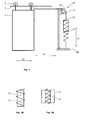
- FIG. 1 shows a shaft door leaf 1 in its open position, the via a roller assembly 2 on a rail. 3 suspended and relative to the rail 3 horizontally displaceable is.
- the rail 3 forms a component of a not further illustrated door frame assembly of a lift shaft.
- the landing door wing 1 is equipped with a safety locking system 10 equipped.
- the security locking system 10 comprises as drive means a drive mass 12 and a spring 14.
- the spring 14 is in the present Embodiment, a coil spring. It can too other types of springs and / or multiple springs used become.
- the drive mass 12 and the spring 14 are at the end a vertical run of a flexible tension element 16 attached.
- the flexible tension member 16 passes over a vertical / horizontal deflection mechanism 18.
- the free end the horizontal run of the flexible tension member 18 is connected to the door 1.
- the spring 14 is, as already described, with its upper End coupled to the flexible tension member 16.
- the lower End of the spring 14 is on a stationary mounting body 20, for example, on the shaft wall, fixed.
- the spring 14 is a in the present embodiment Mainspring. She takes her relaxed position when the Shaft door leaf 1 is in its closed position, and she takes her maximum tense situation when the Shaft door leaf 1 as shown in Fig. 1 in his Open position is.
- Fig. 2A shows how the spring formed as a helical spring 14 may be arranged around the drive mass 12 around. This gives you a mutual leadership for the Drive mass 12 and the spring 14.
- the spring 14 is here as Tension spring shown in relaxed state.
- the spring 14 in an opening of the drive mass 12th is located, one receives a mutual guidance of drive mass 12 and spring 14.
- the spring 14 is here as a tension spring in relaxed state shown.
- Fig. 2C is a variant of a safety-locking system shown in fragmentary form according to the invention. Shown is a door jamb 4, on which the Deflection pulley 18 is attached, via which the flexible Pulling element 16 is running. On flexible tension member 16 is the Drive mass 12 attached.
- the Spring attachment element 22 is on a fixed stop 23rd supported and arranged so that it from the drive mass 12 is movable upwardly from the position shown in FIG. 2C. Opens the shaft door, not shown here, so the drive mass 12 is raised, initially the spring 14 is not stretched.
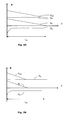
- Fig. 3A shows that of the drive mass 12 at the end of the vertical run of the flexible member 18 force exerted KA, which equals the drive mass multiplied by the Gravity constant g is, as a function of the displacement path 1.
- the end of the horizontal drumming is with the closing door 1 connected.
- other forces on the flexible element in particular the frictional forces acting on the shaft door leaf 1 act.
- the force KA is over the length 1 and also over the time t constant. If only the force KA would work, this would have one Acceleration of the flexible element 16 result, the increases linearly over time. The path traveled would increase with the square of time.
- Fig. 3A further shows that of the spring 14 on the vertical run of the flexible element 16 force applied KF as a function of the displacement path 1 and the spring deflection.
- the end of the horizontal drumming is with the closing door 1 is connected.
- the force KF is maximum, when the spring 14 is maximally stretched, that is when the landing door wing 1 assumes its open position and the spring 14 is extended by ltot.
- the spring 14 acts, while the landing door 1 to its closed position too moving, constantly, albeit with decreasing force.
- the speed caused by the force of the spring 14 of the flexible tension element 16 thus decreases during the Closing movement permanently but declining.
- Fig. 3B shows the balance of forces in an arrangement According to Fig. 2C, that is, if instead of a spring, the ltot acts over the entire displacement path, a spring is used, which only works when the landing door leaf 1 is near its closed position.
- the force KF exerted by such a spring helps Force KA the drive mass 12, the shaft door 1 from to set in motion its open position. Has the Well door leaf 1 then approached its closed position, so only the force KA of the drive mass 12 acts while the force KF of the spring 14 no longer acts. It takes the Speed of the tension element 16 and the shaft door leaf 1 continues to grow, but the increase is lower than when also the spring 14 would work.
- the air resistance can in the present conditions be ignored.
- the total friction includes the friction of the safety locking system, that essentially means the friction of the Deflection arrangement 18, and the friction of the shaft door hanger.
- the friction of the deflection assembly 18 is considered negligible considered.
- the friction of the shaft door hanger is essentially the friction between the rollers 2 of the Shaft door leaf and the rail 3 of the frame assembly 1. In addition, there is the friction of the usually in the lower area guided shaft door leaf.
- the friction is the sliding shaft door suspension a rolling friction.
- rolling friction basically the same Conditions is always lower than sliding friction, but will a suspension with rolling displacement of the shaft door leaf prefers.
- the rolling friction can be considered constant be accepted. It is essentially dependent on the Mass of the shaft door leaf 1 and the friction coefficient, which, in turn, of the materials of relative to each other depend on moving constructive elements. The speed can also influence the rolling friction but in the present case negligible is looked at.
- the during the displacement of the shaft door leaf 1 acting friction as in Figs. 3A, 3B and 3C represented as constant.
- the aim is Avoid friction as much as possible. In the present case but the friction also has an advantage. It diminishes namely, over the entire path of the shaft door leaf 1, the closing force acting on the landing door wing 1 acts. This will indeed the movement of the shaft door leaf 1 initially inhibited, but it will also accelerate of the shaft door wing kept within limits, so that a undesirably high speed of the landing door leaf 1 am The end of his journey is prevented.
- the closing force must also overcome those forces which hold the shaft door 1 in a clamping position. These Forces generally have to be determined experimentally, if there are no empirical values for it. The degree of Wear of the elevator system and the prevailing temperature can play a role here.
Landscapes
- Elevator Door Apparatuses (AREA)
Abstract
Description
Dieses Sicherheits-Schliesssystem hat aber auch gewisse system-immanente Nachteile. Grundsätzlich ist die Antriebsmasse, damit sie überhaupt wirksam werden kann, eine verhältnismässig hohe Masse, die erst beschleunigt werden muss, so dass der Schliessvorgang anfangs träge abläuft. Während die auf den Schachttürflügel wirkende Kraft, mindestens unter Vernachlässigung der Reibung, konstant ist, nimmt die Geschwindigkeit, mit welcher der Schachttürflügel in die Schliessstellung gebracht wird, während des Schliessvorganges zu. Dies hat zur Folge, dass sich der Schachttürflügel zuerst nur langsam bewegt, dafür aber am Ende seines Bewegungsweges mit grosser Geschwindigkeit in die Schliessstellung fällt und dort abrupt angehalten wird. Berücksichtigt man ausserdem die zweifelsfrei vorhandene Reibung, so muss festgestellt werden, dass diese bei Beginn der Wirkung des Sicherheits-Schliesssystems am grössten ist. Dann muss nämlich die Haftreibung überwunden werden, welche zum Beispiel zwischen dem bewegten Schachttürflügel und den nicht-bewegten Rahmenteilen vorhanden ist. Ist der Schachttürflügel einmal in Bewegung, so muss nur noch eine bewegte Reibung, je nach Konstruktion des Schachttürflügels nämlich eine Gleitreibung oder eine Rollreibung, überwunden werden. Damit der Schachttürflügel überhaupt in Bewegung gebracht werden kann, muss also die Antriebsmasse mindestens so gross sein, dass die Haftreibung überwunden werden kann, denn im Moment, in welchem der Schachttürflügel in Bewegung gesetzt werden muss, wirken auf ihn noch keine dynamischen Kräfte sondern nur das Gewicht der Antriebsmasse. Im Weiteren besteht die Gefahr, dass der Schachttürflügel sich nicht wie vorgesehen bewegt, sondern sich in irgend einer Weise verklemmt, so dass zu seiner Bewegung eine entsprechend höhere Kraft eingesetzt werden muss. Ein gewisser Nachteil eines Sicherheits-Schliesssystems mit einer Antriebsmasse kann auch darin gesehen werden, dass eine Umlenkvorrichtung erforderlich ist, weil das Gewicht immer eine vertikale Wirkung ausübt, während die Bewegung des Schachttürflügels im Allgemeinen in horizontaler Richtung erfolgt.
- Fig. 1
- einen Schachttürflügel mit einem Sicherheits-Schliesssystem nach der Erfindung, in stark vereinfachter Darstellung;
- Fig. 2A
- eine Antriebsmasse und eine Feder des Sicherheits-Schliesssystems in einer ersten Anordnung, in vereinfachter und schematisierter Darstellung;
- Fig. 2B
- eine Antriebsmasse und eine Feder des Sicherheits-Schliesssystems in einer zweiten Anordnung, in vereinfachter und schematisierter Darstellung;
- Fig. 2C
- eine Variante des erfindungsgemässen Sicherheits-Schliesssystems, bei welchem die Feder nur über einen Teil des gesamten Weges der Antriebsmasse wirkt;
- Fig. 3A
- die von der Antriebsmasse und der Feder ausgeübten Kräfte sowie die Reibungskraft bei einem Sicher heits-Schliesssystem gemäss Fig. 1; und
- Fig. 3B
- die von der Antriebsmasse und der Feder ausgeübten Kräfte sowie die Reibungskraft bei einem Sicherheits-Schliesssystem gemäss Fig. 2C.
Claims (12)
- Sicherheits-Schliesssystem (10) für einen Schachttürflügel (1) einer Aufzugsanlage, um den Schachttürflügel (1) bei Abwesenheit einer Öffnungskraft in eine Schliessstellung zu bringen, wobei das Sicherheits-Schliesssystem (10) als Antrieb eine in Offenstellung des Schachttürflügels (1) gespannte Feder (14) und eine der Gravitation unterworfene Antriebsmasse (12) aufweist, die mit dem Schachttürflügel (1) gekoppelt sind.
- Sicherheits-Schliesssystem (10) nach Anspruch 1, dadurch gekennzeichnet, dass die Antriebsmasse (12) mindestens eine kritische Masse aufweist, um den Schachttürflügel ohne Mitwirkung der Feder in seine Schliessstellung zu bewegen.
- Sicherheits-Schliesssystem (10) nach einem der Ansprüche 1 bis 2, dadurch gekennzeichnet, dass die Feder (14) eine mechanische Zugfeder, beispielsweise eine Schraubenfeder ist, die vorzugsweise vertikal einbaubar ist.
- Sicherheits-Schliesssystem (10) nach Anspruch 3, dadurch gekennzeichnet, dass die Feder (14) um die Antriebsmasse (12) oder in einem vertikalen Durchbruch der Antriebsmasse (12) angeordnet ist, um eine Führung zwischen Antriebsmasse (12) und Feder (14) zu gewährleisten.
- Sicherheits-Schliesssystem (10) nach einem der Ansprüche 1 bis 4, dadurch gekennzeichnet, dass es einen Umlenkmechanismus (16, 18) aufweist, mit einem flexiblen Zugelement (16), dessen eines Ende mit der Antriebsmasse (12) und der Feder (14) gekoppelt ist, und dessen anderes Ende am Schachttürflügel (1) befestigbar ist, und mit einer vertikal/horizontalen Umlenkanordnung (18), über welche das Zugelement (16) läuft.
- Sicherheits-Schliesssystem (10) nach Anspruch 5, dadurch gekennzeichnet, dass der Umlenkmechanismus (16, 18) im Weiteren eine horizontal/horizontale Umlenkanordnung besitzt, um den Schachttürflügel (1) bei seiner Bewegung in die Schliessstellung horizontal von der Antriebsmasse (12) weg zu bewegen.
- Sicherheits-Schliesssystem (10) nach einem der Ansprüche 1 bis 6, dadurch gekennzeichnet, dass die Feder (14) so ausgebildet und angeordnet ist, dass sie ihre entspannte Lage einnimmt, wenn sich der Schachttürflügel (1) zwischen seiner Offenstellung und einer Mittelstellung, in der er teilweise geschlossen ist, befindet.
- Sicherheits-Schliesssystem (10) nach Anspruch 7, dadurch gekennzeichnet, dass die Feder (14) nicht wirksam ist, wenn sich der Schachttürflügel (1) zwischen seiner Mittelstellung und seiner Schliessstellung befindet.
- Sicherheits-Schliesssystem (10) nach Anspruch 7, dadurch gekennzeichnet, dass die Feder (14) so ausgebildet und angeordnet ist, dass ihre Kraft (KF) der Kraft (KA) der Antriebsmasse (12) entgegenwirkt, wenn sich der Schachttürflügel (1) zwischen seiner Mittelstellung und seiner Schliessstellung befindet.
- Aufzugsanlage mit einem Schachttürflügel (1), welcher ein Sicherheits-Schliesssystem (10) aufweist, um den Schachttürflügel (1) bei Abwesenheit einer Öffnungskraft in eine Schliessstellung zu bringen, wobei das Sicherheits-Schliesssystem (10) als Antrieb eine in Offenstellung des Schachttürflügels (1) gespannte Feder (14) und eine der Gravitation unterworfene Antriebsmasse (12) aufweist, die mit dem Schachttürflügel (1) gekoppelt sind.
- Aufzugsanlage nach Anspruch 10, dadurch gekennzeichnet, dass die Antriebsmasse (12) mindestens eine kritische Masse aufweist, um den Schachttürflügel ohne Mitwirkung der Feder in seine Schliessstellung zu bewegen.
- Aufzugsanlage nach Anspruch 11, dadurch gekennzeichnet, dass die Feder (14) als Schraubenfeder ausgebildet ist und um die Antriebsmasse (12) oder in einem vertikalen Durchbruch der Antriebsmasse (12) angeordnet ist, um eine gegenseitige Führung zwischen Antriebsmasse (12) und Feder (14) zu gewährleisten.
Priority Applications (1)
| Application Number | Priority Date | Filing Date | Title |
|---|---|---|---|
| EP04017613A EP1510495A1 (de) | 2003-08-12 | 2004-07-26 | Sicherheits-Schliesssystem für Schachttüren |
Applications Claiming Priority (3)
| Application Number | Priority Date | Filing Date | Title |
|---|---|---|---|
| EP03405590 | 2003-08-12 | ||
| EP03405590 | 2003-08-12 | ||
| EP04017613A EP1510495A1 (de) | 2003-08-12 | 2004-07-26 | Sicherheits-Schliesssystem für Schachttüren |
Publications (1)
| Publication Number | Publication Date |
|---|---|
| EP1510495A1 true EP1510495A1 (de) | 2005-03-02 |
Family
ID=34105764
Family Applications (1)
| Application Number | Title | Priority Date | Filing Date |
|---|---|---|---|
| EP04017613A Withdrawn EP1510495A1 (de) | 2003-08-12 | 2004-07-26 | Sicherheits-Schliesssystem für Schachttüren |
Country Status (1)
| Country | Link |
|---|---|
| EP (1) | EP1510495A1 (de) |
Cited By (1)
| Publication number | Priority date | Publication date | Assignee | Title |
|---|---|---|---|---|
| CN103422784A (zh) * | 2013-09-05 | 2013-12-04 | 宫文峰 | 偏置配重驱动自动关闭式门 |
Citations (4)
| Publication number | Priority date | Publication date | Assignee | Title |
|---|---|---|---|---|
| US3334444A (en) * | 1966-11-08 | 1967-08-08 | Sanford L Hargrove | Sliding door closer |
| US5285596A (en) * | 1992-11-13 | 1994-02-15 | Kinsey Kenneth M | Door closure apparatus |
| DE19614467A1 (de) * | 1996-04-12 | 1997-10-16 | Aleksander Pajtler | Verstelltüren |
| US6142260A (en) * | 1997-08-19 | 2000-11-07 | Lg Industrial Systems Co. Ltd. | Apparatus for closing hatch doors of an elevator |
-
2004
- 2004-07-26 EP EP04017613A patent/EP1510495A1/de not_active Withdrawn
Patent Citations (4)
| Publication number | Priority date | Publication date | Assignee | Title |
|---|---|---|---|---|
| US3334444A (en) * | 1966-11-08 | 1967-08-08 | Sanford L Hargrove | Sliding door closer |
| US5285596A (en) * | 1992-11-13 | 1994-02-15 | Kinsey Kenneth M | Door closure apparatus |
| DE19614467A1 (de) * | 1996-04-12 | 1997-10-16 | Aleksander Pajtler | Verstelltüren |
| US6142260A (en) * | 1997-08-19 | 2000-11-07 | Lg Industrial Systems Co. Ltd. | Apparatus for closing hatch doors of an elevator |
Cited By (1)
| Publication number | Priority date | Publication date | Assignee | Title |
|---|---|---|---|---|
| CN103422784A (zh) * | 2013-09-05 | 2013-12-04 | 宫文峰 | 偏置配重驱动自动关闭式门 |
Similar Documents
| Publication | Publication Date | Title |
|---|---|---|
| DE69718131T2 (de) | Sicherheitsvorrichtung | |
| DE2753445C2 (de) | ||
| EP2376734B1 (de) | Schiebetür | |
| EP3672898B1 (de) | Hilfsantrieb für eine bremsfangvorrichtung | |
| EP2709941B1 (de) | Aufzugsystem | |
| EP1400476B1 (de) | Fangvorrichtung für Aufzüge | |
| DE3508175C2 (de) | ||
| EP0679602A1 (de) | Mitnehmereinrichtung an Aufzugstüren | |
| DE3730363C1 (en) | Catch device | |
| DE3413236A1 (de) | Fanggeraet fuer ein etwa vertikal in die schliessstellung bewegbares torblatt | |
| EP2477924B1 (de) | Einrichtung zum manuellen lösen einer antriebsbremse in einer aufzugsanlage | |
| EP3045643B1 (de) | Torblatt | |
| DE19533153A1 (de) | Schiebetür mit Notöffnungs- oder Notschließeinrichtung | |
| EP0912811B1 (de) | Schiebetür | |
| DE3912291C1 (de) | ||
| EP0362585B1 (de) | Rolltor | |
| EP1671917A1 (de) | Aufzugsanlage mit Schachttüre und Türschliessvorrichtung | |
| DE102007033412A1 (de) | Rolltor | |
| DE102017104765B4 (de) | Inertervorrichtung für eine Radaufhängung eines Fahrzeugs | |
| EP2549043B1 (de) | Tragsystem für eine Schiebetür | |
| DE2623553C2 (de) | Vorrichtung zum Unterbrechen der Schließbewegung eines Schiebeflügels | |
| EP4486628B1 (de) | Weiche mit auffahrmechanismus | |
| AT502962A1 (de) | Selbstschliesseinrichtung | |
| DE202012011518U1 (de) | Bauaufzug | |
| AT361694B (de) | Kipptor, insbesondere garagentor |
Legal Events
| Date | Code | Title | Description |
|---|---|---|---|
| PUAI | Public reference made under article 153(3) epc to a published international application that has entered the european phase |
Free format text: ORIGINAL CODE: 0009012 |
|
| AK | Designated contracting states |
Kind code of ref document: A1 Designated state(s): AT BE BG CH CY CZ DE DK EE ES FI FR GB GR HU IE IT LI LU MC NL PL PT RO SE SI SK TR |
|
| AX | Request for extension of the european patent |
Extension state: AL HR LT LV MK |
|
| 17P | Request for examination filed |
Effective date: 20050831 |
|
| AKX | Designation fees paid |
Designated state(s): DE FR GB |
|
| REG | Reference to a national code |
Ref country code: HK Ref legal event code: DE Ref document number: 1075034 Country of ref document: HK |
|
| 17Q | First examination report despatched |
Effective date: 20060929 |
|
| GRAP | Despatch of communication of intention to grant a patent |
Free format text: ORIGINAL CODE: EPIDOSNIGR1 |
|
| STAA | Information on the status of an ep patent application or granted ep patent |
Free format text: STATUS: THE APPLICATION IS DEEMED TO BE WITHDRAWN |
|
| 18D | Application deemed to be withdrawn |
Effective date: 20100302 |
|
| REG | Reference to a national code |
Ref country code: HK Ref legal event code: WD Ref document number: 1075034 Country of ref document: HK |