EP1510489A2 - Procédé d'alimentation de feuilles de tôle plates imbriquées - Google Patents
Procédé d'alimentation de feuilles de tôle plates imbriquées Download PDFInfo
- Publication number
- EP1510489A2 EP1510489A2 EP04025493A EP04025493A EP1510489A2 EP 1510489 A2 EP1510489 A2 EP 1510489A2 EP 04025493 A EP04025493 A EP 04025493A EP 04025493 A EP04025493 A EP 04025493A EP 1510489 A2 EP1510489 A2 EP 1510489A2
- Authority
- EP
- European Patent Office
- Prior art keywords
- leading edge
- speed
- holding
- sheet
- metal
- Prior art date
- Legal status (The legal status is an assumption and is not a legal conclusion. Google has not performed a legal analysis and makes no representation as to the accuracy of the status listed.)
- Granted
Links
Images

Classifications
-
- B—PERFORMING OPERATIONS; TRANSPORTING
- B65—CONVEYING; PACKING; STORING; HANDLING THIN OR FILAMENTARY MATERIAL
- B65H—HANDLING THIN OR FILAMENTARY MATERIAL, e.g. SHEETS, WEBS, CABLES
- B65H11/00—Feed tables
- B65H11/002—Feed tables incorporating transport belts
- B65H11/005—Suction belts
-
- B—PERFORMING OPERATIONS; TRANSPORTING
- B65—CONVEYING; PACKING; STORING; HANDLING THIN OR FILAMENTARY MATERIAL
- B65H—HANDLING THIN OR FILAMENTARY MATERIAL, e.g. SHEETS, WEBS, CABLES
- B65H11/00—Feed tables
- B65H11/007—Feed tables with front stop arrangements
-
- B—PERFORMING OPERATIONS; TRANSPORTING
- B65—CONVEYING; PACKING; STORING; HANDLING THIN OR FILAMENTARY MATERIAL
- B65H—HANDLING THIN OR FILAMENTARY MATERIAL, e.g. SHEETS, WEBS, CABLES
- B65H29/00—Delivering or advancing articles from machines; Advancing articles to or into piles
- B65H29/66—Advancing articles in overlapping streams
- B65H29/6654—Advancing articles in overlapping streams changing the overlapping figure
-
- B—PERFORMING OPERATIONS; TRANSPORTING
- B65—CONVEYING; PACKING; STORING; HANDLING THIN OR FILAMENTARY MATERIAL
- B65H—HANDLING THIN OR FILAMENTARY MATERIAL, e.g. SHEETS, WEBS, CABLES
- B65H5/00—Feeding articles separated from piles; Feeding articles to machines
- B65H5/24—Feeding articles in overlapping streams, i.e. by separation of articles from a pile
-
- B—PERFORMING OPERATIONS; TRANSPORTING
- B65—CONVEYING; PACKING; STORING; HANDLING THIN OR FILAMENTARY MATERIAL
- B65H—HANDLING THIN OR FILAMENTARY MATERIAL, e.g. SHEETS, WEBS, CABLES
- B65H9/00—Registering, e.g. orientating, articles; Devices therefor
- B65H9/14—Retarding or controlling the forward movement of articles as they approach stops
-
- B—PERFORMING OPERATIONS; TRANSPORTING
- B65—CONVEYING; PACKING; STORING; HANDLING THIN OR FILAMENTARY MATERIAL
- B65H—HANDLING THIN OR FILAMENTARY MATERIAL, e.g. SHEETS, WEBS, CABLES
- B65H2301/00—Handling processes for sheets or webs
- B65H2301/40—Type of handling process
- B65H2301/44—Moving, forwarding, guiding material
- B65H2301/443—Moving, forwarding, guiding material by acting on surface of handled material
- B65H2301/4433—Moving, forwarding, guiding material by acting on surface of handled material by means holding the material
- B65H2301/44332—Moving, forwarding, guiding material by acting on surface of handled material by means holding the material using magnetic forces
-
- B—PERFORMING OPERATIONS; TRANSPORTING
- B65—CONVEYING; PACKING; STORING; HANDLING THIN OR FILAMENTARY MATERIAL
- B65H—HANDLING THIN OR FILAMENTARY MATERIAL, e.g. SHEETS, WEBS, CABLES
- B65H2301/00—Handling processes for sheets or webs
- B65H2301/40—Type of handling process
- B65H2301/44—Moving, forwarding, guiding material
- B65H2301/443—Moving, forwarding, guiding material by acting on surface of handled material
- B65H2301/4433—Moving, forwarding, guiding material by acting on surface of handled material by means holding the material
- B65H2301/44336—Moving, forwarding, guiding material by acting on surface of handled material by means holding the material using suction forces
-
- B—PERFORMING OPERATIONS; TRANSPORTING
- B65—CONVEYING; PACKING; STORING; HANDLING THIN OR FILAMENTARY MATERIAL
- B65H—HANDLING THIN OR FILAMENTARY MATERIAL, e.g. SHEETS, WEBS, CABLES
- B65H2301/00—Handling processes for sheets or webs
- B65H2301/40—Type of handling process
- B65H2301/44—Moving, forwarding, guiding material
- B65H2301/447—Moving, forwarding, guiding material transferring material between transport devices
- B65H2301/4473—Belts, endless moving elements on which the material is in surface contact
- B65H2301/44732—Belts, endless moving elements on which the material is in surface contact transporting articles in overlapping stream
-
- B—PERFORMING OPERATIONS; TRANSPORTING
- B65—CONVEYING; PACKING; STORING; HANDLING THIN OR FILAMENTARY MATERIAL
- B65H—HANDLING THIN OR FILAMENTARY MATERIAL, e.g. SHEETS, WEBS, CABLES
- B65H2406/00—Means using fluid
- B65H2406/30—Suction means
- B65H2406/32—Suction belts
-
- B—PERFORMING OPERATIONS; TRANSPORTING
- B65—CONVEYING; PACKING; STORING; HANDLING THIN OR FILAMENTARY MATERIAL
- B65H—HANDLING THIN OR FILAMENTARY MATERIAL, e.g. SHEETS, WEBS, CABLES
- B65H2511/00—Dimensions; Position; Numbers; Identification; Occurrences
- B65H2511/20—Location in space
- B65H2511/22—Distance
-
- B—PERFORMING OPERATIONS; TRANSPORTING
- B65—CONVEYING; PACKING; STORING; HANDLING THIN OR FILAMENTARY MATERIAL
- B65H—HANDLING THIN OR FILAMENTARY MATERIAL, e.g. SHEETS, WEBS, CABLES
- B65H2513/00—Dynamic entities; Timing aspects
- B65H2513/10—Speed
-
- B—PERFORMING OPERATIONS; TRANSPORTING
- B65—CONVEYING; PACKING; STORING; HANDLING THIN OR FILAMENTARY MATERIAL
- B65H—HANDLING THIN OR FILAMENTARY MATERIAL, e.g. SHEETS, WEBS, CABLES
- B65H2701/00—Handled material; Storage means
- B65H2701/10—Handled articles or webs
- B65H2701/17—Nature of material
- B65H2701/173—Metal
Definitions
- the invention relates to a method for feeding of flat, scaled overlapping metal sheets to at least one leading edge stop one further processing machine, in particular one Sheet metal or plate varnishing machine.
- the invention is therefore based on the object Method of feeding flat, scaled overlapping metal sheets of the aforementioned To create a way that is precise, reproducible Installation of the respective leading edge of the metal sheets allowed at the leading edge stop. Moreover, should a high number of cycles can be realized.
- a first, having a first funding Conveying zone in which the metal sheets at a first, constant speed in a shingled arrangement with continuous negative pressure or magnetic effect developed Holding effect to be transported and with a second conveying zone following the first conveying zone, which has a second conveying means in which the foremost metal plate in the area of her Front edge taken at a first speed and then to a second speed is slowed down, with the distance (b) between the beginning of the second conveyor and the leading edge one of the foremost metal sheet following Follow-up board at the beginning of the deceleration process the front metal plate bigger than the way is the follow-up board during the deceleration process the front metal plate covers.
- the slowdown also be done in such a way by the second conveying means that the metal sheet from the second conveyor led up to the front edge stop and comes to a standstill there.
- the front panel is the shingled Arrangement of the remaining panels by means of the first Conveyor constantly moved. It is alternative also conceivable that the shingled stream of the first Conveyor is cyclically promoted. This means, a cyclic speed change make: high speed - low speed etc ..
- the inventive approach prevents the follow-up board during the deceleration process of the previous panel the second funding runs and undefined is slowed down. Is the front panel exactly aligned, it becomes of a further processing mechanism in exactly aligned position accepted.
- the second funding accelerates during the mentioned alignment process again a speed equal to the first conveyor corresponds, so that then the now foremost Metal sheet of the scale arrangement of the second Funding taken and -esammlung as before slowed down and at the leading edge stop is aligned exactly.
- no sliding movement occurs in the main phase between the second conveyor and metal sheet.
- the metal sheet is exactly the second conveyor (Riementrum) according to a fixed, during each bar same place - Machine angle motion law slows down.
- Holding effect by vacuum is dimensioned that the curve of the deceleration is independent is of panel weight and surface texture the metal sheet.
- the movement of second funding and plate is in the slowdown phase synchronous, without relative movement. Just before arriving at the leading edge stop, especially at the leading brands, this is Adhesion closed (by switching off the vacuum), so that the second funding then the Metal plate still pushes, but only with a very low power resulting from the now present Friction without vacuum between strand and metal sheet results.
- the scaling is made such that during the deceleration process of the foremost ones Blackboard the overlap zone with the follow-up board increased.
- the formats of the respectively to be supplied Items can be a high processing rate realize per unit of time. Things lie on the first and second funding on, that means the objects are above the funding; therefore there is no overhead transport before, in which the objects at the Bottom of the funds are kept. This is of importance, inter alia, because the Scaling of the objects is designed in such a way that the foremost panel was underrun by the succeeding one etc., so that the panels from below only in the non-overlapped area alone are accessible. As mentioned, there is thus one Slowing down to a relatively low speed. Does the item have this low speed Assuming he slides a short Piece over the pad and get this way and way against the leading edge stop and will aligned there.
- the invention relates to a method for feeding of shallow, scaled overlapping Metal sheets to at least one leading edge stop a further processing machine, in particular a sheet metal or plate varnishing machine, in particular according to claim 1, with a first Conveying zone in which the metal sheets with a first, constant speed in a shingled arrangement with continuous by negative pressure or magnetic Effect of developed holding effect of a first holding device to be transported and with a second, the first holding zone following Conveying zone in which the respective foremost metal sheet in the area of its leading edge at first speed taken over and then to a second speed is slowed down, with the distance (c) from the front edge of the foremost metal sheet at the beginning of slowing down until the end of the first one Holding device is greater than the scale length, the dimension between the front edge of a metal sheet and the leading edge of an immediately following Metal sheet is in the unbraked state.
- the invention relates to a method for feeding of shallow, scaled overlapping Metal sheets to at least one leading edge stop a further processing machine, in particular a sheet metal or plate varnishing machine, in particular according to claim 1 and / or 2, with a first conveyor zone, in which the metal sheets with a first, constant speed in shingled Arrangement with continuous by negative pressure or magnetic effect developed holding effect transported a first holding device and with a second, the first production zone following conveyor zone, in which the respectively foremost Metal sheet in the area of its front edge with first Taken speed and then to a second Speed slows down, so she's having the second speed against at least one Leading edge stop is led or with this speed approaches the leading edge stop, the foremost metal sheet during her Slowing down in a stationary holding zone of a second holding device of the second conveying zone by switchable negative pressure or switchable magnetic Effect is maintained and this holding effect is switched off as soon as the front edge of the foremost Metal sheet with only a small distance to the leading edge stop lies, whereby after plant and thereby aligning the foremost ones Metal sheet at
- the first funding a first holding device is assigned.
- Prefers can the second conveyor a second holding device be assigned.
- the first and / or the second holding device may be preferred as Suction device and / or designed as a magnetic device be.
- the suction device is designed in such a way that the objects, especially the Metal sheets, on the surface of the conveyor be held by suction, so that a relative movement between the corresponding funding and the objects is safely avoided. In particular, can be due to this holding effect the braking process without slipping the Carry out metal sheet on the conveyor, so that achieves high precision with high cycle speed is.
- the objects are ferromagnetic Components, for example steel sheet panels, act as a holding device and a Magnetic device can be used, located below of the conveyor and in this way and a relative displacement between metal sheet and funding prevented.
- the metal sheets thus move exactly with the speed, given by the appropriate funding is.
- first Conveying an endless revolving conveyor is used.
- first and second funds thus to Trums, the preferred from several, parallel adjacent belts assure on which the metal sheets rest, wherein below the upper strand, the holding device is arranged, which the metal sheet respectively Fix / fix the metal sheets on the belt.
- the holding means the second holding device in the transport direction Seen - only over a portion of the second conveyor he follows. For a location fix this is Section sufficient and holds the fixation zone relatively small, so for the holding effect only to apply correspondingly small amounts of energy are.
- the holding action the second holding device switched on and off is.
- the Vacuum source on and off or it there is a pneumatically acting switching valve in the system with which the suction effect can be switched on and off is.
- the suction is activated as soon as the foremost metal sheet from the second conveyor is taken over; it is deactivated or greatly reduced just before the leading edge the braked metal sheet on the leading edge stop meets.
- a magnetic device is present for unfolding the holding effect is preferably a solenoid device used, so that by electrical input or Turn off the holding force activatable or can be deactivated.
- the holding action of the first holding device acts preferably continuously, that is, it will not connected. Exception: at the last panel of the Shingled current is switched.
- the first and / or the second holding device of at least one below the first and / or second Conveyor located suction box is formed.
- the suction box is preferably via a switching valve connected to a vacuum source.
- To the suction effect by the first and / or the second conveying means passing through on the tablets is the first and / or the second conveying means permeable to air educated.
- the second speed is much smaller as the first speed; it preferably points very little value or it will be like that Proceeded that the board down to the speed Zero is slowed down and that when reaching standstill the leading edge of the panel against the leading edge stop occurs.
- the first speed in a Rated speed corresponding to about 9,000 to 10,000 boards per hour the first speed about 1 m / s.
- the second speed can for example, a value of about 0.2 or 0.1 m / s exhibit.
- the second speed at 0.25 to 0.1 times the first speed is designed.
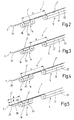
- FIG. 1 shows a device 1 for feeding of flat objects 2 against at least one Leading edge stop 3.
- the objects 2 are as Sheet metal 4 is formed.
- the device 1 has a first conveying means 5 and a second conveying means 6.
- the first subsidy 5 is surrounded by a roundtrum 7 and the second conveyor 6 of a circulating Trum 8 formed.
- the circumferential Trum 7 has a Upper strand 9 and a lower strand 10 and is at one End led around a guide wheel 11. That at the other End lying deflection wheel of the run 7 is on the figure not shown for reasons of space.
- the circulating Trum 8 has at each end a deflection wheel 12 or 13. His upper run 14 lies in the plane of the upper strand 9 and its lower strand 15 is guided over a tension roller 16.
- the circulating runs 7 and 8 are made respectively a plurality of spaced-apart belts, so that one spread over the width of the metal sheets arranged support is formed.
- the belt are corresponding pulleys 11 to 13 and Tensioning rollers 16 assigned.
- the belts of the strands 7 and 8 are made permeable to air.
- a suction box 17 indicated in the figure, which is connected to a vacuum source.
- the strands 7 and 8 thus form Saugtrums on which the objects are held immovably by negative pressure.
- the strand 7 runs by means of a not shown, preferably electric drive with a constant, first speed v 1 to.
- the transport direction is indicated by means of the arrow 20 with respect to a transport plane 21.
- a speed or controllable electric or mechanical drive drives the strand 8 in such a way that it is also correspondingly accelerated and decelerated in the transport direction (arrow 20). It has the instantaneous velocity v 2 .
- the metal sheets 4 are in a shingled arrangement to each other, the means the frontmost sheet metal panel 4 'overlaps the following braiding panel 4 ", wherein the leading edge area the metal sheet 4 "below the trailing edge area the metal sheet 4 'is located. Further, adjoining the follower panel 4 '' upstream Metal sheets are scaled accordingly (not shown).
- the suction box 17 forms a first holding device 22, the vacuum plates 4 in maruppter arrangement fixed on the upper run 9.
- the holding action of the first holding device 22 is constant.
- the suction box 18 forms a second holding device 23 for the most recent Metal sheet 4 ', wherein the holding action means of the switching valve 19 on and off or strengthened and diminished, that is, the vacuum source is with the suction box 18 connected or there is a separation of the connection.
- the metal sheets are generally with denoted by the reference numeral 4, the first lying Metal sheet bears the reference numeral 4 'and the Following table the reference numeral 4 ''.
- the metal sheets 4 are supplied in a shingled arrangement by means of the run 7. They rest on the upper side of the upper run 9 and are fixed by the effect of the negative pressure of the suction box 17.
- the negative pressure acting on the corresponding metal sheet 4 is "switched off" by overlap by the follower board 4.
- the switching valve 19 By appropriate position of the switching valve 19 it is ensured that a negative pressure is built up in the suction box 18 so that a region of the metal sheet 4 'is established. sucked firmly onto the top of the upper run 14 and the metal plate 4 'is thus maintained in immovable position to the upper run 14. the structure of the negative pressure takes place only upon complete covering of the suction box 18 through the metal plate 4'.
- the run 7 continues to run at the speed v 1 , so that the follower table 4 "is pushed a corresponding distance further under the metal plate 4 '. If the foremost metal sheet 4 'is aligned exactly at the leading edge stop 3, then it is gripped at its front edge 25 and fed into the transport direction (arrow 20) for further processing. Before reaching the leading edge stop 3, the negative pressure in the suction box 18 is turned off by means of actuation of the switching valve 19.
- Figures 2 to 5 show the device of the figure 1 in schematic form, the following Terms such as “beginning” and “end”, seen in the transport direction of the metal sheets 4 are defined, ie in the direction of arrow 20 of the Figure 1. Accordingly, according to Figure 2, the distance a between the end of the second holding device 23 and the end of the first holding device 22 supplemented for a security surcharge, the metal sheets go through in time for a complete Negative pressure buildup is required, less than the scale length between the plates. Under scale length the scaled arranged metal sheets 4 is the dimension between the front edge of a metal sheet 4 and the leading edge of the immediately following Plate 4 to understand. Because of the mentioned Distance a is a secure takeover of the Sheet metal 4 from strand 7 on the strand 8 possible.
- the distance b is between the beginning of the second conveyor and the leading edge of a Follow-up board 4 "at the beginning of the deceleration process the predecessor panel 4 'larger than the way the Follow-up board 4 "during the deceleration process the predecessor panel 4 'covers.
- the follower board 4 runs during the Slowing down the predecessor panel 4 'on the second conveyor 6 and is undefined pre brakes.
- the distance between the leading edge stop 3 and the leading edge the following table 4 "(dimension d) at the time of Switching on the vacuum (negative pressure in the suction box 18) is smaller than the distance from the leading edge stop 3 until the end of the second holding device 23 (measure e). If this were not the case, then the vacuum would catch the metal sheet 4 straight to be aligned.
- the to be aligned Predecessor sheet 4 'must be switched on when switching on Vacuum (for the follow-up board 4 '') of this underschuppt be.
- FIG. 5 as an alternative embodiment, with reference to reference numeral 28, a device is indicated which adopts a slowed-down metal sheet 4 'after the vacuum of the suction box 18 has been switched off.
- the acquisition takes place at the delayed, very low speed v 2 .
- the device 28, which is only indicated schematically, guides the metal sheet 4 'with further delay up to the front edge stop 3, so that there is a controlled, reproducible alignment.
- the invention thus preferably relates to a slowing of the metal sheets in the phase of feeding the respective leading edge to an alignment stop by means of circulating vacuum suction belts, wherein the respective delayed sheet metal sheet is detected non-positively.
- the deceleration is preferably at a speed v 2 which is approximately 10% of the speed v1 or close to zero.
- the deceleration is then made to a defined speed to gently drive the panel against the leading edge stop.
- the aligned at the leading edge stop panel is preferably transferred to a system not shown and not described, in order to process the metal sheets in a defined position can.
- a high braking accuracy or positioning accuracy is achieved by driving a speed-way profile in the same way for each panel in the machine cycle. There is a scratch-free introduction of force into the panels due to the negative pressure or a magnetic position.
- the metal sheets 4, 4 ' are each completely flat lying slowed down.
- the surface of the slowdown device (second conveyor 6) is located in the tabletop level.
- the slowdown from below carried out because the underside of the metal sheets on the conveyor 5 and 6 rests.
- This solution is chosen, though to hold the corresponding metal sheet 4 'by means of vacuum or Magnetic force only the area of the panel from below accessible, which is not in overlapping position to the next table.
Landscapes
- Engineering & Computer Science (AREA)
- Mechanical Engineering (AREA)
- Separation, Sorting, Adjustment, Or Bending Of Sheets To Be Conveyed (AREA)
- Sheets, Magazines, And Separation Thereof (AREA)
- Delivering By Means Of Belts And Rollers (AREA)
- Registering Or Overturning Sheets (AREA)
- Feeding Of Articles By Means Other Than Belts Or Rollers (AREA)
Applications Claiming Priority (3)
| Application Number | Priority Date | Filing Date | Title |
|---|---|---|---|
| DE10017259 | 2000-04-06 | ||
| DE10017259A DE10017259B4 (de) | 2000-04-06 | 2000-04-06 | Verfahren zum Zuführen von Gegenständen |
| EP01108246A EP1155996B1 (fr) | 2000-04-06 | 2001-03-31 | Procédé d'alimentation de feuilles de tôle |
Related Parent Applications (1)
| Application Number | Title | Priority Date | Filing Date |
|---|---|---|---|
| EP01108246A Division EP1155996B1 (fr) | 2000-04-06 | 2001-03-31 | Procédé d'alimentation de feuilles de tôle |
Publications (3)
| Publication Number | Publication Date |
|---|---|
| EP1510489A2 true EP1510489A2 (fr) | 2005-03-02 |
| EP1510489A3 EP1510489A3 (fr) | 2005-04-20 |
| EP1510489B1 EP1510489B1 (fr) | 2009-09-09 |
Family
ID=7637875
Family Applications (2)
| Application Number | Title | Priority Date | Filing Date |
|---|---|---|---|
| EP01108246A Expired - Lifetime EP1155996B1 (fr) | 2000-04-06 | 2001-03-31 | Procédé d'alimentation de feuilles de tôle |
| EP04025493A Expired - Lifetime EP1510489B1 (fr) | 2000-04-06 | 2001-03-31 | Procédé d'alimentation de feuilles de tôle plates imbriquées |
Family Applications Before (1)
| Application Number | Title | Priority Date | Filing Date |
|---|---|---|---|
| EP01108246A Expired - Lifetime EP1155996B1 (fr) | 2000-04-06 | 2001-03-31 | Procédé d'alimentation de feuilles de tôle |
Country Status (5)
| Country | Link |
|---|---|
| US (1) | US6575460B2 (fr) |
| EP (2) | EP1155996B1 (fr) |
| JP (1) | JP2001354348A (fr) |
| DE (3) | DE10017259B4 (fr) |
| ES (2) | ES2331244T3 (fr) |
Cited By (1)
| Publication number | Priority date | Publication date | Assignee | Title |
|---|---|---|---|---|
| EP2586613A1 (fr) | 2011-10-26 | 2013-05-01 | Grafometal, S.A. | Lame décapeuse |
Families Citing this family (10)
| Publication number | Priority date | Publication date | Assignee | Title |
|---|---|---|---|---|
| ES2181588B1 (es) * | 2001-05-23 | 2004-06-01 | Asm, S.A. | Maquina transportadora y apiladora para chapas magneticas y no magneticas. |
| DE10205488A1 (de) * | 2002-02-09 | 2003-08-21 | Peter Weiss | Saugriementransportsystem |
| AU2003285732A1 (en) * | 2003-12-08 | 2005-06-24 | Hewlett-Packard Development Company, L.P. | Bounce prevention |
| US7209612B2 (en) * | 2004-03-24 | 2007-04-24 | Enablence Inc. | Two-stage optical bi-directional transceiver |
| DE102004015335A1 (de) * | 2004-03-30 | 2005-10-20 | Koenig & Bauer Ag | Vorrichtung zum Zuführen eines geschuppten Bogenstromes |
| DE102008006562A1 (de) * | 2008-01-29 | 2009-10-15 | Böwe Systec AG | Verfahren und Vorrichtung zum Transport von Papier in einer Papierhandhabungsanlage von einem ersten Transport an einen zweiten Transport |
| EP2112099B1 (fr) * | 2008-04-21 | 2012-05-23 | Kesper Druckwalzen GmbH | Dispositif pour positionner une pièce à être traitée sur sa surface |
| DE102017221217B4 (de) * | 2017-11-27 | 2021-04-29 | Koenig & Bauer Ag | Bogenverarbeitende Maschine |
| DE102021118468B3 (de) * | 2021-07-16 | 2022-08-18 | Koenig & Bauer Ag | Maschinenanordnung mit mehreren jeweils Bogen bearbeitenden Bearbeitungsstationen |
| CN113928908B (zh) * | 2021-09-29 | 2023-09-19 | 广东利元亨智能装备股份有限公司 | 一种料带的切割装置、方法、设备和存储介质 |
Family Cites Families (13)
| Publication number | Priority date | Publication date | Assignee | Title |
|---|---|---|---|---|
| US2257117A (en) * | 1938-03-31 | 1941-09-30 | Miller Printing Machinery Co | Sheet handling mechanism |
| DE1152707B (de) * | 1961-12-27 | 1963-08-14 | Mabeg Maschb G M B H Nachf Hen | Zwischen Anlegefoerdertisch und Vordermarken wirksame Bogenverlangsamungs- und Ausricht-vorrichtung |
| US3380734A (en) * | 1966-04-19 | 1968-04-30 | Kimberly Clark Co | Papermaking machine |
| US3507489A (en) * | 1966-09-06 | 1970-04-21 | Masson Scott Thrissell Eng Ltd | Sheet feeding apparatus |
| US4451027A (en) * | 1980-01-09 | 1984-05-29 | Burroughs Corp. | Constant spacing document feeder |
| DE3331662A1 (de) * | 1983-09-02 | 1985-03-28 | M.A.N.- Roland Druckmaschinen AG, 6050 Offenbach | Verfahren und vorrichtung zum passgenauen bogentransport in eine druckmaschine |
| ATE55965T1 (de) * | 1988-01-13 | 1990-09-15 | Ferag Ag | Verfahren und vorrichtung zum veraendern des ueberlappungsgrades von in einem schuppenstrom gefoerderten druckereiprodukten. |
| DE4013302A1 (de) * | 1990-04-26 | 1991-10-31 | Koenig & Bauer Ag | Vorrichtung zum foerdern eines insbesondere geschuppten stroms von bogen |
| DE4119511A1 (de) * | 1991-06-13 | 1992-12-17 | Jagenberg Ag | Vorrichtung zum abbremsen von auf einem stapel abzulegenden boegen, insbesondere papier- oder kartonboegen |
| JP3478629B2 (ja) * | 1994-01-27 | 2003-12-15 | ハイデルベルガー ドルツクマシーネン アクチエンゲゼルシヤフト | 紙葉処理機械の給紙領域において紙葉を搬送する装置および電動モータの速度制御方法 |
| DE4433912C2 (de) * | 1994-09-23 | 1996-07-11 | Ltg Lufttechnische Gmbh | Stapelvorrichtung mit oberer Tafelführung |
| US6305285B1 (en) * | 1996-09-25 | 2001-10-23 | Crabtree Of Gateshead Ltd. | Sheet settling system |
| DE19645239B4 (de) * | 1996-11-02 | 2007-06-06 | Man Roland Druckmaschinen Ag | Bogenanlage, insbesondere für Druckmaschinen |
-
2000
- 2000-04-06 DE DE10017259A patent/DE10017259B4/de not_active Expired - Fee Related
-
2001
- 2001-03-31 ES ES04025493T patent/ES2331244T3/es not_active Expired - Lifetime
- 2001-03-31 DE DE50105279T patent/DE50105279D1/de not_active Expired - Lifetime
- 2001-03-31 EP EP01108246A patent/EP1155996B1/fr not_active Expired - Lifetime
- 2001-03-31 ES ES01108246T patent/ES2236074T3/es not_active Expired - Lifetime
- 2001-03-31 DE DE50115104T patent/DE50115104D1/de not_active Expired - Lifetime
- 2001-03-31 EP EP04025493A patent/EP1510489B1/fr not_active Expired - Lifetime
- 2001-04-04 US US09/826,322 patent/US6575460B2/en not_active Expired - Fee Related
- 2001-04-06 JP JP2001108439A patent/JP2001354348A/ja active Pending
Cited By (1)
| Publication number | Priority date | Publication date | Assignee | Title |
|---|---|---|---|---|
| EP2586613A1 (fr) | 2011-10-26 | 2013-05-01 | Grafometal, S.A. | Lame décapeuse |
Also Published As
| Publication number | Publication date |
|---|---|
| EP1510489A3 (fr) | 2005-04-20 |
| EP1155996A2 (fr) | 2001-11-21 |
| DE50115104D1 (de) | 2009-10-22 |
| US20020008003A1 (en) | 2002-01-24 |
| EP1155996B1 (fr) | 2005-02-09 |
| US6575460B2 (en) | 2003-06-10 |
| JP2001354348A (ja) | 2001-12-25 |
| DE10017259B4 (de) | 2006-10-26 |
| EP1155996A3 (fr) | 2003-01-02 |
| ES2331244T3 (es) | 2009-12-28 |
| EP1510489B1 (fr) | 2009-09-09 |
| ES2236074T3 (es) | 2005-07-16 |
| DE50105279D1 (de) | 2005-03-17 |
| DE10017259A1 (de) | 2001-10-18 |
Similar Documents
| Publication | Publication Date | Title |
|---|---|---|
| EP1072548B1 (fr) | Dispositif et méthode pour empiler des articles plats | |
| EP2008956B1 (fr) | Dispositif d'introduction exacte de marchandises en forme de plaques et procédé correspondant | |
| EP0498068B1 (fr) | Plieuse, dans laquelle le transport d'exemplaires pliés est realisé en passant par des moyens de transport, des galets partiels et des cordons | |
| EP1155996B1 (fr) | Procédé d'alimentation de feuilles de tôle | |
| DE102013100232A1 (de) | Verfahren und Vorrichtung zur Herstellung variabler Lücken zwischen Artikeln oder Artikelgruppen eines Artikelstroms | |
| EP3025970A1 (fr) | Dispositif de cerclage de produits empiles | |
| DE2058606A1 (de) | Verfahren und Vorrichtung zum seitlichen Ausrichten von Blaettern,insbesondere bei einer Druckpresse | |
| EP0698573B1 (fr) | Dispositif pour convoyer des tôles | |
| DE2638783C3 (de) | Bogenanleger | |
| DE3330681A1 (de) | Verfahren zum schnellen zufuehren und transportieren von blattfoermigen papiererzeugnissen und vorrichtung zur durchfuehrung des verfahrens | |
| DE102011086983B4 (de) | Vorrichtung zum Stapeln von Furnierblättern | |
| EP0216023B1 (fr) | Dispositif pour ordonner un courant d'articles se chevauchant | |
| EP0499691A1 (fr) | Procédé pour traiter des produits imprimés alimentés de façon continue en une formation imbriquée ainsi que dispositif pour la mise en oeuvre dudit procédé | |
| DE2853114C2 (de) | Vorrichtung zum Überführen von Packungen von einer Produktionsmaschine zu einer Weiterverarbeitungsmaschine | |
| DE2129089A1 (de) | Einrichtung zur Überleitung von Gegenstanden, vorzugsweise Buchblocks, von einer Fordereinrichtung auf eine zweite Fördereinrichtung mit anderer Fordergeschwindigkeit | |
| DE68905648T2 (de) | Verfahren und einrichtung zum stapeln von mit einer schere produzierten blechen, insbesondere aus einem blechband. | |
| EP0458733A2 (fr) | Méthode et dispositif pour transporter des produits imprimés | |
| EP1851145B1 (fr) | Dispositif et procede d'acheminement cadence de produits en bois | |
| EP1044154B1 (fr) | Dispositif pour transformer une pile d'objets recouvrants en une formation a recouvrement | |
| DE102006023988B3 (de) | Anordnung zum Beschleunigen oder Verzögern von in einem Fördersystem transportierten Fördergütern | |
| DE10044068A1 (de) | Verfahren zur Steuerung der Bogenzufuhr | |
| EP0503530A1 (fr) | Dispositif pour former une suite d'objets se chevauchant par le dessous | |
| CH684085A5 (de) | Verfahren zum Oeffnen von aussermittig gefalteten Druckereiprodukten und Vorrichtung zur Durchführung des Verfahrens. | |
| DD235682A5 (de) | Absetzeinrichtung fuer liegende flacherzeugnisse oder waesche | |
| DE10137196C1 (de) | Transportbahn für eine Schlauchbeutelverpackungsmaschine |
Legal Events
| Date | Code | Title | Description |
|---|---|---|---|
| PUAI | Public reference made under article 153(3) epc to a published international application that has entered the european phase |
Free format text: ORIGINAL CODE: 0009012 |
|
| AC | Divisional application: reference to earlier application |
Ref document number: 1155996 Country of ref document: EP Kind code of ref document: P |
|
| AK | Designated contracting states |
Kind code of ref document: A2 Designated state(s): DE ES GB IT |
|
| PUAL | Search report despatched |
Free format text: ORIGINAL CODE: 0009013 |
|
| AK | Designated contracting states |
Kind code of ref document: A3 Designated state(s): DE ES GB IT |
|
| RIN1 | Information on inventor provided before grant (corrected) |
Inventor name: HORELD, ANDREAS, DIPL.-ING. Inventor name: MOKLER, BERNHARD, DIPL.-ING. Inventor name: VOLLMANN, ANDREAS, DIPL.-ING. |
|
| 17P | Request for examination filed |
Effective date: 20051020 |
|
| AKX | Designation fees paid |
Designated state(s): DE ES GB IT |
|
| 17Q | First examination report despatched |
Effective date: 20060113 |
|
| GRAP | Despatch of communication of intention to grant a patent |
Free format text: ORIGINAL CODE: EPIDOSNIGR1 |
|
| GRAS | Grant fee paid |
Free format text: ORIGINAL CODE: EPIDOSNIGR3 |
|
| RAP1 | Party data changed (applicant data changed or rights of an application transferred) |
Owner name: KBA-METALPRINT GMBH |
|
| GRAA | (expected) grant |
Free format text: ORIGINAL CODE: 0009210 |
|
| AC | Divisional application: reference to earlier application |
Ref document number: 1155996 Country of ref document: EP Kind code of ref document: P |
|
| AK | Designated contracting states |
Kind code of ref document: B1 Designated state(s): DE ES GB IT |
|
| REG | Reference to a national code |
Ref country code: GB Ref legal event code: FG4D Free format text: NOT ENGLISH |
|
| REF | Corresponds to: |
Ref document number: 50115104 Country of ref document: DE Date of ref document: 20091022 Kind code of ref document: P |
|
| REG | Reference to a national code |
Ref country code: ES Ref legal event code: FG2A Ref document number: 2331244 Country of ref document: ES Kind code of ref document: T3 |
|
| PLBE | No opposition filed within time limit |
Free format text: ORIGINAL CODE: 0009261 |
|
| STAA | Information on the status of an ep patent application or granted ep patent |
Free format text: STATUS: NO OPPOSITION FILED WITHIN TIME LIMIT |
|
| 26N | No opposition filed |
Effective date: 20100610 |
|
| REG | Reference to a national code |
Ref country code: DE Ref legal event code: R082 Ref document number: 50115104 Country of ref document: DE Representative=s name: JUERGEN STIEL, DE |
|
| REG | Reference to a national code |
Ref country code: DE Ref legal event code: R082 Ref document number: 50115104 Country of ref document: DE |
|
| PGFP | Annual fee paid to national office [announced via postgrant information from national office to epo] |
Ref country code: IT Payment date: 20200331 Year of fee payment: 20 Ref country code: DE Payment date: 20200302 Year of fee payment: 20 Ref country code: GB Payment date: 20200324 Year of fee payment: 20 |
|
| PGFP | Annual fee paid to national office [announced via postgrant information from national office to epo] |
Ref country code: ES Payment date: 20200402 Year of fee payment: 20 |
|
| REG | Reference to a national code |
Ref country code: DE Ref legal event code: R071 Ref document number: 50115104 Country of ref document: DE |
|
| REG | Reference to a national code |
Ref country code: GB Ref legal event code: PE20 Expiry date: 20210330 |
|
| PG25 | Lapsed in a contracting state [announced via postgrant information from national office to epo] |
Ref country code: GB Free format text: LAPSE BECAUSE OF EXPIRATION OF PROTECTION Effective date: 20210330 |
|
| REG | Reference to a national code |
Ref country code: ES Ref legal event code: FD2A Effective date: 20220128 |
|
| PG25 | Lapsed in a contracting state [announced via postgrant information from national office to epo] |
Ref country code: ES Free format text: LAPSE BECAUSE OF EXPIRATION OF PROTECTION Effective date: 20210401 |