EP1510340B1 - Inkjet nozzle actuated by slotted plunger - Google Patents
Inkjet nozzle actuated by slotted plunger Download PDFInfo
- Publication number
- EP1510340B1 EP1510340B1 EP04024063A EP04024063A EP1510340B1 EP 1510340 B1 EP1510340 B1 EP 1510340B1 EP 04024063 A EP04024063 A EP 04024063A EP 04024063 A EP04024063 A EP 04024063A EP 1510340 B1 EP1510340 B1 EP 1510340B1
- Authority
- EP
- European Patent Office
- Prior art keywords
- ink
- nozzle
- actuator
- ink jet
- plunger
- Prior art date
- Legal status (The legal status is an assumption and is not a legal conclusion. Google has not performed a legal analysis and makes no representation as to the accuracy of the status listed.)
- Expired - Lifetime
Links
Images


Classifications
-
- B—PERFORMING OPERATIONS; TRANSPORTING
- B41—PRINTING; LINING MACHINES; TYPEWRITERS; STAMPS
- B41J—TYPEWRITERS; SELECTIVE PRINTING MECHANISMS, i.e. MECHANISMS PRINTING OTHERWISE THAN FROM A FORME; CORRECTION OF TYPOGRAPHICAL ERRORS
- B41J3/00—Typewriters or selective printing or marking mechanisms characterised by the purpose for which they are constructed
- B41J3/44—Typewriters or selective printing mechanisms having dual functions or combined with, or coupled to, apparatus performing other functions
- B41J3/445—Printers integrated in other types of apparatus, e.g. printers integrated in cameras
-
- B—PERFORMING OPERATIONS; TRANSPORTING
- B41—PRINTING; LINING MACHINES; TYPEWRITERS; STAMPS
- B41J—TYPEWRITERS; SELECTIVE PRINTING MECHANISMS, i.e. MECHANISMS PRINTING OTHERWISE THAN FROM A FORME; CORRECTION OF TYPOGRAPHICAL ERRORS
- B41J2/00—Typewriters or selective printing mechanisms characterised by the printing or marking process for which they are designed
- B41J2/005—Typewriters or selective printing mechanisms characterised by the printing or marking process for which they are designed characterised by bringing liquid or particles selectively into contact with a printing material
- B41J2/01—Ink jet
- B41J2/135—Nozzles
- B41J2/14—Structure thereof only for on-demand ink jet heads
- B41J2/14314—Structure of ink jet print heads with electrostatically actuated membrane
-
- B—PERFORMING OPERATIONS; TRANSPORTING
- B41—PRINTING; LINING MACHINES; TYPEWRITERS; STAMPS
- B41J—TYPEWRITERS; SELECTIVE PRINTING MECHANISMS, i.e. MECHANISMS PRINTING OTHERWISE THAN FROM A FORME; CORRECTION OF TYPOGRAPHICAL ERRORS
- B41J2/00—Typewriters or selective printing mechanisms characterised by the printing or marking process for which they are designed
- B41J2/005—Typewriters or selective printing mechanisms characterised by the printing or marking process for which they are designed characterised by bringing liquid or particles selectively into contact with a printing material
- B41J2/01—Ink jet
- B41J2/135—Nozzles
- B41J2/14—Structure thereof only for on-demand ink jet heads
- B41J2/14427—Structure of ink jet print heads with thermal bend detached actuators
-
- B—PERFORMING OPERATIONS; TRANSPORTING
- B41—PRINTING; LINING MACHINES; TYPEWRITERS; STAMPS
- B41J—TYPEWRITERS; SELECTIVE PRINTING MECHANISMS, i.e. MECHANISMS PRINTING OTHERWISE THAN FROM A FORME; CORRECTION OF TYPOGRAPHICAL ERRORS
- B41J2/00—Typewriters or selective printing mechanisms characterised by the printing or marking process for which they are designed
- B41J2/005—Typewriters or selective printing mechanisms characterised by the printing or marking process for which they are designed characterised by bringing liquid or particles selectively into contact with a printing material
- B41J2/01—Ink jet
- B41J2/135—Nozzles
- B41J2/16—Production of nozzles
- B41J2/1621—Manufacturing processes
- B41J2/1623—Manufacturing processes bonding and adhesion
-
- B—PERFORMING OPERATIONS; TRANSPORTING
- B41—PRINTING; LINING MACHINES; TYPEWRITERS; STAMPS
- B41J—TYPEWRITERS; SELECTIVE PRINTING MECHANISMS, i.e. MECHANISMS PRINTING OTHERWISE THAN FROM A FORME; CORRECTION OF TYPOGRAPHICAL ERRORS
- B41J2/00—Typewriters or selective printing mechanisms characterised by the printing or marking process for which they are designed
- B41J2/005—Typewriters or selective printing mechanisms characterised by the printing or marking process for which they are designed characterised by bringing liquid or particles selectively into contact with a printing material
- B41J2/01—Ink jet
- B41J2/135—Nozzles
- B41J2/16—Production of nozzles
- B41J2/1621—Manufacturing processes
- B41J2/1626—Manufacturing processes etching
- B41J2/1628—Manufacturing processes etching dry etching
-
- B—PERFORMING OPERATIONS; TRANSPORTING
- B41—PRINTING; LINING MACHINES; TYPEWRITERS; STAMPS
- B41J—TYPEWRITERS; SELECTIVE PRINTING MECHANISMS, i.e. MECHANISMS PRINTING OTHERWISE THAN FROM A FORME; CORRECTION OF TYPOGRAPHICAL ERRORS
- B41J2/00—Typewriters or selective printing mechanisms characterised by the printing or marking process for which they are designed
- B41J2/005—Typewriters or selective printing mechanisms characterised by the printing or marking process for which they are designed characterised by bringing liquid or particles selectively into contact with a printing material
- B41J2/01—Ink jet
- B41J2/135—Nozzles
- B41J2/16—Production of nozzles
- B41J2/1621—Manufacturing processes
- B41J2/1626—Manufacturing processes etching
- B41J2/1629—Manufacturing processes etching wet etching
-
- B—PERFORMING OPERATIONS; TRANSPORTING
- B41—PRINTING; LINING MACHINES; TYPEWRITERS; STAMPS
- B41J—TYPEWRITERS; SELECTIVE PRINTING MECHANISMS, i.e. MECHANISMS PRINTING OTHERWISE THAN FROM A FORME; CORRECTION OF TYPOGRAPHICAL ERRORS
- B41J2/00—Typewriters or selective printing mechanisms characterised by the printing or marking process for which they are designed
- B41J2/005—Typewriters or selective printing mechanisms characterised by the printing or marking process for which they are designed characterised by bringing liquid or particles selectively into contact with a printing material
- B41J2/01—Ink jet
- B41J2/135—Nozzles
- B41J2/16—Production of nozzles
- B41J2/1621—Manufacturing processes
- B41J2/1631—Manufacturing processes photolithography
-
- B—PERFORMING OPERATIONS; TRANSPORTING
- B41—PRINTING; LINING MACHINES; TYPEWRITERS; STAMPS
- B41J—TYPEWRITERS; SELECTIVE PRINTING MECHANISMS, i.e. MECHANISMS PRINTING OTHERWISE THAN FROM A FORME; CORRECTION OF TYPOGRAPHICAL ERRORS
- B41J2/00—Typewriters or selective printing mechanisms characterised by the printing or marking process for which they are designed
- B41J2/005—Typewriters or selective printing mechanisms characterised by the printing or marking process for which they are designed characterised by bringing liquid or particles selectively into contact with a printing material
- B41J2/01—Ink jet
- B41J2/135—Nozzles
- B41J2/16—Production of nozzles
- B41J2/1621—Manufacturing processes
- B41J2/1632—Manufacturing processes machining
-
- B—PERFORMING OPERATIONS; TRANSPORTING
- B41—PRINTING; LINING MACHINES; TYPEWRITERS; STAMPS
- B41J—TYPEWRITERS; SELECTIVE PRINTING MECHANISMS, i.e. MECHANISMS PRINTING OTHERWISE THAN FROM A FORME; CORRECTION OF TYPOGRAPHICAL ERRORS
- B41J2/00—Typewriters or selective printing mechanisms characterised by the printing or marking process for which they are designed
- B41J2/005—Typewriters or selective printing mechanisms characterised by the printing or marking process for which they are designed characterised by bringing liquid or particles selectively into contact with a printing material
- B41J2/01—Ink jet
- B41J2/135—Nozzles
- B41J2/16—Production of nozzles
- B41J2/1621—Manufacturing processes
- B41J2/1635—Manufacturing processes dividing the wafer into individual chips
-
- B—PERFORMING OPERATIONS; TRANSPORTING
- B41—PRINTING; LINING MACHINES; TYPEWRITERS; STAMPS
- B41J—TYPEWRITERS; SELECTIVE PRINTING MECHANISMS, i.e. MECHANISMS PRINTING OTHERWISE THAN FROM A FORME; CORRECTION OF TYPOGRAPHICAL ERRORS
- B41J2/00—Typewriters or selective printing mechanisms characterised by the printing or marking process for which they are designed
- B41J2/005—Typewriters or selective printing mechanisms characterised by the printing or marking process for which they are designed characterised by bringing liquid or particles selectively into contact with a printing material
- B41J2/01—Ink jet
- B41J2/135—Nozzles
- B41J2/16—Production of nozzles
- B41J2/1621—Manufacturing processes
- B41J2/1637—Manufacturing processes molding
- B41J2/1639—Manufacturing processes molding sacrificial molding
-
- B—PERFORMING OPERATIONS; TRANSPORTING
- B41—PRINTING; LINING MACHINES; TYPEWRITERS; STAMPS
- B41J—TYPEWRITERS; SELECTIVE PRINTING MECHANISMS, i.e. MECHANISMS PRINTING OTHERWISE THAN FROM A FORME; CORRECTION OF TYPOGRAPHICAL ERRORS
- B41J2/00—Typewriters or selective printing mechanisms characterised by the printing or marking process for which they are designed
- B41J2/005—Typewriters or selective printing mechanisms characterised by the printing or marking process for which they are designed characterised by bringing liquid or particles selectively into contact with a printing material
- B41J2/01—Ink jet
- B41J2/135—Nozzles
- B41J2/16—Production of nozzles
- B41J2/1621—Manufacturing processes
- B41J2/164—Manufacturing processes thin film formation
- B41J2/1642—Manufacturing processes thin film formation thin film formation by CVD [chemical vapor deposition]
-
- B—PERFORMING OPERATIONS; TRANSPORTING
- B41—PRINTING; LINING MACHINES; TYPEWRITERS; STAMPS
- B41J—TYPEWRITERS; SELECTIVE PRINTING MECHANISMS, i.e. MECHANISMS PRINTING OTHERWISE THAN FROM A FORME; CORRECTION OF TYPOGRAPHICAL ERRORS
- B41J2/00—Typewriters or selective printing mechanisms characterised by the printing or marking process for which they are designed
- B41J2/005—Typewriters or selective printing mechanisms characterised by the printing or marking process for which they are designed characterised by bringing liquid or particles selectively into contact with a printing material
- B41J2/01—Ink jet
- B41J2/135—Nozzles
- B41J2/16—Production of nozzles
- B41J2/1621—Manufacturing processes
- B41J2/164—Manufacturing processes thin film formation
- B41J2/1643—Manufacturing processes thin film formation thin film formation by plating
-
- B—PERFORMING OPERATIONS; TRANSPORTING
- B41—PRINTING; LINING MACHINES; TYPEWRITERS; STAMPS
- B41J—TYPEWRITERS; SELECTIVE PRINTING MECHANISMS, i.e. MECHANISMS PRINTING OTHERWISE THAN FROM A FORME; CORRECTION OF TYPOGRAPHICAL ERRORS
- B41J2/00—Typewriters or selective printing mechanisms characterised by the printing or marking process for which they are designed
- B41J2/005—Typewriters or selective printing mechanisms characterised by the printing or marking process for which they are designed characterised by bringing liquid or particles selectively into contact with a printing material
- B41J2/01—Ink jet
- B41J2/135—Nozzles
- B41J2/16—Production of nozzles
- B41J2/1621—Manufacturing processes
- B41J2/164—Manufacturing processes thin film formation
- B41J2/1645—Manufacturing processes thin film formation thin film formation by spincoating
-
- B—PERFORMING OPERATIONS; TRANSPORTING
- B41—PRINTING; LINING MACHINES; TYPEWRITERS; STAMPS
- B41J—TYPEWRITERS; SELECTIVE PRINTING MECHANISMS, i.e. MECHANISMS PRINTING OTHERWISE THAN FROM A FORME; CORRECTION OF TYPOGRAPHICAL ERRORS
- B41J2/00—Typewriters or selective printing mechanisms characterised by the printing or marking process for which they are designed
- B41J2/005—Typewriters or selective printing mechanisms characterised by the printing or marking process for which they are designed characterised by bringing liquid or particles selectively into contact with a printing material
- B41J2/01—Ink jet
- B41J2/135—Nozzles
- B41J2/16—Production of nozzles
- B41J2/1621—Manufacturing processes
- B41J2/164—Manufacturing processes thin film formation
- B41J2/1646—Manufacturing processes thin film formation thin film formation by sputtering
-
- B—PERFORMING OPERATIONS; TRANSPORTING
- B41—PRINTING; LINING MACHINES; TYPEWRITERS; STAMPS
- B41J—TYPEWRITERS; SELECTIVE PRINTING MECHANISMS, i.e. MECHANISMS PRINTING OTHERWISE THAN FROM A FORME; CORRECTION OF TYPOGRAPHICAL ERRORS
- B41J2/00—Typewriters or selective printing mechanisms characterised by the printing or marking process for which they are designed
- B41J2/005—Typewriters or selective printing mechanisms characterised by the printing or marking process for which they are designed characterised by bringing liquid or particles selectively into contact with a printing material
- B41J2/01—Ink jet
- B41J2/135—Nozzles
- B41J2/16—Production of nozzles
- B41J2/1648—Production of print heads with thermal bend detached actuators
-
- B—PERFORMING OPERATIONS; TRANSPORTING
- B41—PRINTING; LINING MACHINES; TYPEWRITERS; STAMPS
- B41J—TYPEWRITERS; SELECTIVE PRINTING MECHANISMS, i.e. MECHANISMS PRINTING OTHERWISE THAN FROM A FORME; CORRECTION OF TYPOGRAPHICAL ERRORS
- B41J2/00—Typewriters or selective printing mechanisms characterised by the printing or marking process for which they are designed
- B41J2/005—Typewriters or selective printing mechanisms characterised by the printing or marking process for which they are designed characterised by bringing liquid or particles selectively into contact with a printing material
- B41J2/01—Ink jet
- B41J2/17—Ink jet characterised by ink handling
- B41J2/175—Ink supply systems ; Circuit parts therefor
- B41J2/17596—Ink pumps, ink valves
-
- B—PERFORMING OPERATIONS; TRANSPORTING
- B41—PRINTING; LINING MACHINES; TYPEWRITERS; STAMPS
- B41J—TYPEWRITERS; SELECTIVE PRINTING MECHANISMS, i.e. MECHANISMS PRINTING OTHERWISE THAN FROM A FORME; CORRECTION OF TYPOGRAPHICAL ERRORS
- B41J2/00—Typewriters or selective printing mechanisms characterised by the printing or marking process for which they are designed
- B41J2/005—Typewriters or selective printing mechanisms characterised by the printing or marking process for which they are designed characterised by bringing liquid or particles selectively into contact with a printing material
- B41J2/01—Ink jet
- B41J2/015—Ink jet characterised by the jet generation process
- B41J2/04—Ink jet characterised by the jet generation process generating single droplets or particles on demand
- B41J2002/041—Electromagnetic transducer
Definitions
- the present invention relates to the field of ink jet printing systems.
- Ink jet printers themselves come in many different types.
- the utilisation of a continuous stream ink in ink jet printing appears to date back to at least 1929 wherein US Patent No. 1941001 by Hansell discloses a simple form of continuous stream electro-static ink jet printing.
- US Patent 3596275 by Sweet also discloses a process of a continuous ink jet printing including the step wherein the ink jet stream is modulated by a high frequency electro-static field so as to cause drop separation. This technique is still utilized by several manufacturers including Elmjet and Scitex (see also US Patent No. 3373437 by Sweet et al)
- Piezo-electric ink jet printers are also one form of commonly utilized ink jet printing device. Piezo-electric systems are disclosed by Kyser et. al. in US Patent No. 3946398 (1970) which utilises a diaphragm mode of operation, by Zolten in US Patent 3683212 (1970) which discloses a squeeze mode of operation of a piezo electric crystal, Stemme in US Patent No. 3747120 (1972) discloses a bend mode of piezo-electric operation, Howkins in US Patent No. 4459601 discloses a Piezo electric push mode actuation of the ink jet stream and Fischbeck in US 4584590 which discloses a sheer mode type of piezo-electric transducer element
- the ink jet printing techniques include those disclosed by Endo et al in GB 2007162 (1979) and Vaught et al in US Patent 4490728. Both the aforementioned references disclosed ink jet printing techniques rely upon the activation of an electrothermal actuator which results in the creation of a bubble in a constricted space, such as a nozzle, which thereby causes the ejection of ink from an aperture connected to the confined space onto a relevant print media.
- Printing devices utilising the electro-thermal actuator are manufactured by manufacturers such as Canon and Hewlett Packard.
- magnetic devices are known, e.g. JP 04 126 255.
- a printing technology should have a number of desirable attributes. These include inexpensive construction and operation, high speed operation, safe and continuous long term operation etc. Each technology may have its own advantages and disadvantages in the areas of cost, speed, quality, reliability, power usage, simplicity of construction operation, durability and consumables.
- esoteric techniques are also often utilized. These can include electroforming of nickel stage (Hewlett-Packard Journal, Vol. 36 no 5, pp33-37 (1985)), electro-discharge machining, laser ablation (U.S. Patent No. 5,208,604), micro-punching, etc.
- the invention provides a nozzle arrangement according to claim 1 with advantageous embodiments provided in the dependent claims.
- the preferred embodiments and other embodiments will be discussed under separate headings with the heading including an IJ number for ease of reference.
- the headings also include a type designator with T indicating thermal, S indicating shutter type and F indicating a field type.
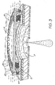
- Fig. 1 there is illustrated an exploded perspective view illustrating the construction of a single ink jet nozzle 4 in accordance with the principles of the present invention.
- the nozzle 4 operates on the principle of electro-mechanical energy conversion and comprises a solenoid 11 which is connected electrically at a first end 12 to a magnetic plate 13 which is in turn connected to a current source e.g. 14 utilized to activate the ink nozzle 4.
- the magnetic plate 13 can be constructed from electrically conductive iron.
- a second magnetic plunger 15 is also provided, again being constructed from soft magnetic iron. Upon energizing the solenoid 11, the plunger 15 is attracted to the fixed magnetic plate 13. The plunger thereby pushes against the ink within the nozzle 4 creating a high pressure zone in the nozzle chamber 17. This causes a movement of the ink in the nozzle chamber 17 and in a first design, subsequent ejection of an ink drop.
- a series of apertures e.g. 20 is provided so that ink in the region of solenoid 11 is squirted out of the holes 20 in the top of the plunger 15 as it moves towards lower plate 13. This prevents ink trapped in the area of solenoid 11 from increasing the pressure on the plunger 15 and thereby increasing the magnetic forces needed to move the plunger 15.
- Fig. 2 there is illustrated 30 a timing diagram of the plunger current control signal.
- the solenoid current is activated 31 for the movement of the plunger and ejection of a drop from the ink nozzle.
- the current to the solenoid is turned off.
- a reverse current is applied having approximately half the magnitude of the forward current.
- the reverse current 32 causes the plunger to move backwards towards its original position.
- a series of torsional springs 22, 23 (Fig. 1) also assists in the return of the plunger to its original position.
- a meniscus at the nozzle tip is formed with an approximately a concave hemispherical surface.
- the surface tension will exert a net forward force on the ink which will result in nozzle refilling.
- the repetition rate of the nozzle 4 is therefore principally determined by the nozzle refill time which will be 100micro- seconds, depending on the device geometry, ink surface tension and the volume of the ejected drop.
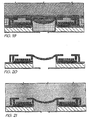
- Fig. 3 an important aspect of the operation of the electro-magnetically driven print nozzle will now be described.
- the plate 15 Upon a current flowing through the coil 11, the plate 15 becomes strongly attracted to the plate 13.
- the plate 15 experiences a downward force and begins movement towards the plate 13. This movement imparts a momentum to the ink within the nozzle chamber 17.
- the ink is subsequently ejected as hereinbefore described.
- the movement of the plate 15 causes a build-up of pressure in the area 64 between the plate 15 and the coil 11. This build-up would normally result in a reduced effectiveness of the plate 15 in ejecting ink.
- the plate 15 preferably includes a series of apertures e.g. 20 which allow for the flow of ink from the area 64 back into the ink chamber and thereby allow a reduction in the pressure in area 64. This results in an increased effectiveness in the operation of the plate 15.
- the apertures 20 are of a teardrop shape increasing in diameter with increasing radial distance of the plunger.
- the aperture profile thereby providing minimal disturbance of the magnetic flux through the plunger while maintaining structural integrity of plunger 15.
- the current through coil 11 is reversed resulting in a repulsion of the two plates 13, 15. Additionally, the torsional spring e.g. 23 acts to return the plate 15 to its initial position.
- a torsional spring e.g. 23 has a number of substantial benefits including a compact layout, and the construction of the torsional spring from the same material and same processing steps as that of the plate 15.
- the top surface of plate 15 does not include a series of apertures. Rather, the inner radial surface 25 of plate 15 comprises slots of substantially constant cross-sectional profile in fluid communication between the nozzle chamber 17 and the area 64 between plate 15 and the solenoid 11.
- the plate 15 Upon activation of the coil 11, the plate 15 is attracted to the armature plate 13 and experiences a force directed towards plate 13.
- fluid in the area 64 is compressed and experiences a higher pressure than its surrounds.
- the flow of fluid takes place out of the slots in the inner radial surface 25 plate 15 into the nozzle chamber 17.
- the flow of fluid into chamber 17, in addition to the movement of the plate 15, causes the ejection of ink out of the ink nozzle port 24.
- the movement of the plate 15 causes the torsional springs, for example 23, to be resiliently deformed.
- the coil 11 is deactivated and a slight reverse current is applied.
- the reverse current acts to repel the plate 15 from the armature plate 13.
- the torsional springs, for example 23, act as additional means to return the plate 15 to its initial or quiescent position.
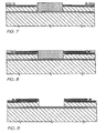
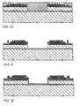
- the nozzle apparatus is constructed from the following main parts including a nozzle tip 40 having an aperture 24 which can be constructed from boron doped silicon.
- the radius of the aperture 24 of the nozzle tip is an important determinant of drop velocity and drop size.
- CMOS silicon layer 42 is provided upon which is fabricated all the data storage and driving circuitry 41 necessary for the operation of the nozzle 4.
- a nozzle chamber 17 is also constructed.
- the nozzle chamber 17 should be wide enough so that viscous drag from the chamber walls does not significantly increase the force required of the plunger. It should also be deep enough so that any air ingested through the nozzle port 24 when the plunger returns to its quiescent state does not extend to the plunger device. If it does, the ingested bubble may form a cylindrical surface instead of a hemispherical surface resulting in the nozzle not refilling properly.
- a CMOS dielectric and insulating layer containing various current paths parts for the current connection to the plunger device is also provided 44.
- a fixed plate of ferroelectric material having two parts 13, 46.
- the two parts 13, 46 are electrically insulated from one another.
- a solenoid 11 is provided.
- This can comprise a spiral coil of deposited copper.
- Preferably a single spiral layer is utilized to avoid fabrication difficulty and copper is used for a low resistivity and high electro-migration resistance.
- a plunger 15 of ferromagnetic material is provided to maximize the magnetic force generated.
- the plunger 15 and fixed magnetic plate 13, 46 surround the solenoid 11 as a torus. Thus, little magnetic flux is lost and the flux is concentrated around the gap between the plunger 15 and the fix plate 13,46.
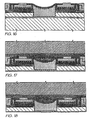
- the gap between the fixed plate 13, 46 and the plunger 15 is one of the most important "parts" of the print nozzle 4.
- the size of the gap will strongly affect the magnetic force generated, and also limits the travel of the plunger 15.
- a small gap is desirable to achieve a strong magnetic force, but a large gap is desirable to allow longer plunger 15 to travel, and therefore allow smaller plunger radius to be utilized.
- the springs, e.g. 22, 23 for returning to the plunger 15 to its quiescent position after a drop has been ejected are provided.
- the springs, e.g. 22, 23 can be fabricated from the same material, and in the same processing steps, as the plunger 15.
- the springs, e.g. 22, 23 act as torsional springs in their interaction with the plunger 15.
- passivation layers which may be silicon nitride (Si 3 N 4 ), diamond like carbon (DLC), or other chemically inert, highly impermeable layer.
- the passivation layers are especially important for device lifetime, as the active device will be immersed in the ink.
- the presently disclosed ink jet printing technology is potentially suited to a wide range of printing system including: colour and monochrome office printers, short run digital printers, high speed digital printers, offset press supplemental printers, low cost scanning printers high speed pagewidth printers, notebook computers with inbuilt pagewidth printers, portable colour and monochrome printers, colour and monochrome copiers, colour and monochrome facsimile machines, combined printer, facsimile and copying machines, label printers, large format plotters, photograph copiers, printers for digital photographic "minilabs", video printers, PhotoCD printers, portable printers for PDAs, wallpaper printers, indoor sign printers, billboard printers, fabric printers, camera printers and fault tolerant commercial printer arrays.
- the embodiments of the invention use an ink jet printer type device. Of course many different devices could be used. However presently popular ink jet printing technologies are unlikely to be suitable.
- thermal inkjet The most significant problem with thermal inkjet is power consumption. This is approximately 100 times that required for high speed, and stems from the energy-inefficient means of drop ejection. This involves the rapid boiling of water to produce a vapor bubble which expels the ink. Water has a very high heat capacity, and must be superheated in thermal inkjet applications. This leads to an efficiency of around 0.02%, from electricity input to drop momentum (and increased surface area) out.
- piezoelectric inkjet The most significant problem with piezoelectric inkjet is size and cost. Piezoelectric cystals have a very small deflection at reasonable drive voltages, and therefore require a large area for each nozzle. Also, each piezoelectric actuator must be connected to its drive circuit on a separate substrate. This is not a significant problem at the current limit of around 300 nozzles per print head, but is a major impediment to the fabrication of pagewide print heads with 19,200 nozzles.
- the inkjet technologies used meet the stringent requirements of in-camera digital color printing and other high quality, high speed, low cost printing applications.
- new inkjet technologies have been created.
- the target features include:
- inkjet designs shown here are suitable for a wide range of digital printing systems, from battery powered one-time use digital cameras, through to desktop and network printers, and through to commercial printing systems
- the print head is designed to be a monolithic 0.5 micron CMOS chip with MEMS post processing.
- the print head is 100 mm long, with a width which depends upon the inkjet type.
- the smallest print head designed is IJ38, which is 0.35 mm wide, giving a chip area of 35 square mm.
- the print beads each contain 19.200 nozzles plus data and control circuitry.
- Ink is supplied to the back of the print head by injection molded plastic ink channels.
- the molding requires 50 micron features, which can be created using a lithographically micromachined insert in a standard injection molding tool.
- Ink flows through holes etched through the wafer to the nozzle chambers fabricated on the front surface of the wafer.
- the print head is connected to the camera circuitry by tape automated bonding.
- inkjet configurations can readily be derived from these 45 examples by substituting alternative configurations along one or more of the 11 axes.
- Most of the IJ01 to IJ45 examples can be made into inkjet print heads with characteristics superior to any currently available inkjet technology.
- Suitable applications include: Home printers, Office network printers, Short run digital printers, Commercial print systems, Fabric printers, Pocket printers, Internet WWW printers, Video printers, Medical imaging, Wide format printers, Notebook PC printers, Fax machines, Industrial printing systems, Photocopier, Photographic minilabs etc.
- Piezoelectric A piezoelectric crystal such as lead lanthanum zirconate (PZT) is electrically activated, and either expands, shears, or bends to apply pressure to the ink, ejecting drops.
- PZT lead lanthanum zirconate
- the conductive plates may be in a comb or honeycomb structure, or stacked to increase the surface area and therefore the force.
- Low power consumption ⁇ Difficult to operate electrostatic devices in an aqueous environment ⁇ IJ02, IJ04 ⁇ Many ink types can be used ⁇
- the electrostatic actuator will normallyneed to be separated from the ink ⁇
- Fast operation ⁇ Very large area required to achieve high forces ⁇
- High voltage drive transistors may be required ⁇
- Full pagewidth print heads are not competitive due to actuator size
- Electrostatic pull on ink A strong electric field is applied to the ink, whereupon electrostatic attraction accelerates the ink towards the print medium.
- Examples are: Samarium Cobalt (SaCo) and magnetic materials in the neodymium iron boron family (NdFeB, NdDyFeBNb, NdDyFeB, etc) ⁇ Low power consumption ⁇ Complex fabrication ⁇ IJ07, IJ10 ⁇ Many ink types can be used ⁇ Permanent magnetic material such as Neodymium Iron Boron (NdFeB) required.
- SaCo Samarium Cobalt
- NdDyFeBNb neodymium iron boron family
- NdDyFeB neodymium iron boron family
- NdFeB Neodymium Iron Boron
- Soft magnetic core electro-magnetic A solenoid induced a magnetic field in a soft magnetic core or yoke fabricated from a ferrous material such as electroplated iron alloys such as CoNiFe [1], CoFe, or NiFealloys. Typically, the soft magnetic material is in two parts, which are normally held apart by a spring. When the solenoid is actuated, the two parts attract, displacing the ink.
- the actuator uses the giant magnetostrictive effect of materials such as Terfenol-D (an alloy of terbium, dysprosium and iron developed at the Naval Ordnance Laboratory, hence Ter-Fe-NOL). For best efficiency, the actuator should be pre-stressed to approx. 8 MPa.
- a heater fabricated from a conductive material is incorporated.
- a 50 ⁇ m long PTFE bend actuator with polysilicon heater and 15 mW power input can provide 180 ⁇ N force and 10 ⁇ m deflection.
- Actuator motions include: ⁇ High force can be generated ⁇ Requires special material (e.g.
- the conducting polymer expands when resistively heated. ⁇ High force can be generated ⁇ Requires special materials development (High CTE conductive polymer) ⁇ IJ24
- conducting dopants include: ⁇ Very low power consumption ⁇ Requires a PTFE deposition process, which is not yet standard in ULS1 fabs 1) Carbon nanotubes ⁇ Many ink types can be used ⁇ PTFE deposition cannot be followed with high temperature (above 350 °C) processing 2) Metal fibers ⁇ Simple planar fabrication ⁇ Evaporation and CVD deposition techniques cannot be used 3) Conductive polymers such as doped polythiophene ⁇ Small chin area required for each actuator ⁇ Pigmented inks may be infeasible, as pigment particles may jam the bend actuator 4) Carbon granules ⁇ Fast operation ⁇ High efficiency ⁇ CMOS compatible voltages and currents ⁇ Easy extension from single nozzles to pagewidth print heads Shape memory alloy A shape memory alloy such as TiNi (also known as Nitinol
- Linear Magnetic Actuator Linear magnetic actuators include the Linear Induction Actuator (LIA), Linear Permanent Magnet Synchronous Actuator (LPMSA), Linear Reluctance Synchronous Actuator (LRSA), Linear Switched Reluctance Actuator (LSRA), and the Linear Step
- Linear Magnetic actuators can be constructed with high thrust, long travel, and high efficiency using planar semiconductor fabrication techniques ⁇ Requires unusual semiconductor materials such as soft magnetic alloys (e.g. CoNiFe [1]) ⁇ IJ12 ⁇ Long actuator travel is available ⁇ Some varieties also require permanent magnetic materials such as Neodymium iron boron (NdFeB) ⁇ Medium force is available ⁇ Requires complex multi-phase drive circuitry ⁇ Low voltage operation ⁇ High current operation Basic operation mode Operational mode Description Advantages Disadvantages Examples Actuator directly pushes ink This is the simplest mode of operation: the actuator directly supplies sufficient kinetic energy to expel the drop. The drop must have a sufficient velocity to overcome the surface tension. ⁇ Simple operation.
- Drop repetition rate is usually limited to less than 10 KHz. However, this is not fundamental to the method, but is related to the refill method normally used ⁇ Thermal inkjet ⁇ No external fields required ⁇ All of the drop kinetic energy must be provided by the actuator ⁇ Piezoelectric inkjet ⁇ Satellite drops can be avoided if drop velocity is less than 4 m/s ⁇ Satellite drops usually form if drop velocity is greater than 4.5 m/s ⁇ IJ01, IJ02, IJ03, IJ04 ⁇ Can be efficient, depending upon the actuator used ⁇ IJ05, IJ06, IJ07, IJ09 ⁇ IJ11, IJ12, IJ14, IJ16 ⁇ IJ20, IJ22, IJ23, IJ24 ⁇ IJ25, IJ26, IJ27, IJ28 ⁇ IJ29, IJ30, IJ31, IJ32 ⁇ IJ33, IJ34, IJ35, IJ36 ⁇ IJ37, IJ38, IJ39, IJ40
- Very simple print head fabrication can be used ⁇ Requires very high electrostatic field ⁇ Silverbrook, EP 0771 658 A2 and related patent applications ⁇
- the drop selection means does not need to provide the energy required to separate the drop from the nozzle ⁇ Electrostatic field for small nozzle sizes is above air breakdown ⁇ Tone-Jet ⁇ Electrostatic field may attract dust Magnetic pull on ink
- the drops to be printed are selected by some manner (e.g. thermally induced surface tension reduction of pressurized ink). Selected drops are separated from the ink in the nozzle by a strong magnetic field acting on the magnetic ink.
- Actuators with small travel can be used ⁇ Moving parts are required ⁇ IJ08, IJ15, IJ18, IJ19 ⁇ Actuators with small force can be used ⁇ Requires ink pressure modulator ⁇ High speed (>50 KHz) operation can be achieved ⁇ Friction and wear must be considered ⁇ Stiction is possible Pulsed magnetic pull on ink pusher A pulsed magnetic field attracts an 'ink pusher' at the drop ejection frequency. An actuator controls a catch, which prevents the ink pusher from moving when a drop is not to be ejected.
- Oscillating ink pressure can provide a refill pulse, allowing higher operating speed ⁇ Requires external ink pressure oscillator ⁇ Silverbrook, EP 0771 658 A2 and related patent applications ⁇
- the actuators may operate with much lower energy ⁇ Ink pressure phase and amplitude must be carefully controlled ⁇ IJ08, IJ13, IJ15, IJ17 ⁇ Acoustic lenses can be used to focus the sound on the nozzles ⁇ Acoustic reflections in the ink chamber must be designed for ⁇ IJ18, IJ19, IJ21 Media proximity
- the print head is placed in close proximity to the print medium. Selected drops protrude from the print head further than unselected drops, and contact the print medium. The drop soaks into the medium fast enough to cause drop separation.
- Transient bend actuator A trilayer bend actuator where the two outside layers are identical. This cancels bend due to ambient temperature and residual stress. The actuator only responds to transient heating of one side or the other.
- Actuator stack A series of thin actuators are stacked. This can be appropriate where actuators require high electric field strength, such as electrostatic and piezoelectric actuators. ⁇ Increased travel ⁇ Increased fabrication complexity ⁇ Some piezoelectric ink jets ⁇ Reduced drive voltage ⁇ Increased possibility of short circuits due to pinholes ⁇ IJ04 Multiple actuators Multiple smaller actuators are used simultaneously to move the ink. Each actuator need provide only a portion of the force required.
- Actuator forces may not add linearly, reducing efficiency ⁇ IJ12, IJ13, IJ18, IJ20 ⁇
- Multiple actuators can be positioned to control ink flow accurately ⁇ IJ22, IJ28, IJ42, IJ43 Linear Spring
- a linear spring is used to transform a motion with small travel and high force into a longer travel, lower force motion.
- Matches low travel actuator with higher travel requirements ⁇ Requires print head area for the spring ⁇ IJ15 ⁇
- Non-contact method of motion transformation Reverse spring The actuator loads a spring. When the actuator is turned off, the spring releases.
- Low force, low travel actuators can be used ⁇ Moving parts are required ⁇ IJ13 ⁇ Can be fabricated using standard surface MEMS processes ⁇ Several actuator cycles are required ⁇ More complex drive electronics ⁇ Complex construction ⁇ Friction, friction, and wear are possible Catch The actuator controls a small catch. The catch either enables or disables movement of an ink pusher that is controlled In a bulk manner. ⁇ Very low actuator energy ⁇ Complex construction ⁇ IJ10 ⁇ Very small actuator size ⁇ Requires external force ⁇ Unsuitable for pigmented inks Buckle plate A buckle plate can be used to change a slow actuator into a fast motion. It can also convert a high force, low travel actuator into a high travel, medium force motion.
- acoustic lens is used to concentrate sound waves.
- No moving parts Large area required ⁇ Only relevant for acoustic ink jets ⁇ 1993 Hadimioglu et al, EUP 550,192 ⁇ 1993 Elrod et al, EUP 572,220 Sharp conductive point A sharp point is used to concentrate an electrostatic field.
- Simple construction ⁇ Difficult to fabricate using standard VLSI processes for a surface ejecting ink-jet ⁇ Tone-jet ⁇ Only relevant for electrostatic ink jets Actuator motion Actuator motion Description Advantages Disadvantages Examples Volume expansion The volume of the actuator changes, pushing the ink in all directions.
- the effective area of the actuator becomes the membrane area ⁇ Fabrication complexity ⁇ 1982 Howkins USP 4,459,601 ⁇ Actuator size ⁇ Difficulty of integration in a VLSI process
- Rotary levers may be used to increase travel
- Device complexity ⁇ IJ05, IJ08, IJ13, IJ28 ⁇ Small chip area requirements ⁇ May have friction at a pivot point Bend
- the actuator bends when energized. This may be due to differential thermal expansion, piezoelectric expansion, magnetostriction, or other form of relative dimensional change. ⁇ A very small change in dimensions can be converted to a large motion.
- the motion of the free end of the actuator ejects the ink.
- Easy to fabricate as a planar VLSI process ⁇ Difficult to fabricate for non-planar devices ⁇ IJ17, IJ21, IJ34, IJ35 ⁇ Small area required, therefore low cost ⁇ Poor out-of-plane stiffness
- Nozzle Clearing method Description Advantages Disadvantages Examples Normal nozzle firing All of the nozzles are fired periodically, before the ink has a chance to dry. When not in use the nozzles are sealed (capped) against air. ⁇ No added complexity on the print head ⁇ May not be sufficient to displace dried ink ⁇ Most ink jet systems The nozzle firing is usually performed during a special clearing cycle, after first moving the print head to a cleaning station.
- Effectiveness depends substantially upon the configuration of the inkjet nozzle ⁇ May be used with: In some configurations, this may cause heat build-up at the nozzle which boils the ink, clearing the nozzle. In other situations, it may cause sufficient vibrations to dislodge clogged nozzles.
- nozzle clearing may be assisted by providing an enhanced drive signal to the actuator.
- a high nozzle clearing capability can be achieved ⁇ High implementation cost if ⁇ IJ08, IJ13, IJ15, IJ17 ⁇ May be implemented at very low cost in systems which already include acoustic actuators system does not already include an acoustic actuator ⁇ IJ18, IJ19, IJ21 Nozzle clearing plate A microfabricated plate is pushed against the nozzles. The plate has a post for every nozzle.
- the blade is usually fabricated from a flexible polymer, e.g. rubber or synthetic elastomer.
- ⁇ Effective for planar print head surfaces ⁇ Difficult to use if print head surface is non-planar or very fragile ⁇ Many ink jet systems ⁇ Low cost ⁇ Requires mechanical parts ⁇ Blade can wear out in high volume print systems Separate ink boiling beater A separate heater is provided at the nozzle although the normal drop e-ection mechanism does not require it. The heaters do not require individual drive circuits, as many nozzles can be cleared simultaneously, and no imaging is required.
- Nozzles may be clogged by adhesive Glass capillaries Fine glass capillaries are drawn from glass tubing. This method has been used for making individual nozzles, but is difficult to use for bulk manufacturing of print heads with thousands of nozzles. ⁇ No expensive equipment required ⁇ Very small nozzle sizes are difficult to form ⁇ 1970 Zoltan USP 3,683,212 ⁇ Simple to make single nozzles ⁇ Not suited for mass production Monolithic, surface micro-machined using VLSI lithographic processes The nozzle plate is deposited as a layer using standard VLS1 deposition techniques.
- Nozzles are etched in the nozzle plate using VLSI lithography and etching.
- High accuracy ( ⁇ 1 ⁇ m) ⁇ Requires sacrificial layer under the nozzle plate to form the nozzle chamber ⁇ Silverbrook, EP 0771 658 A2 and related patent applications ⁇ Monolithic ⁇ Surface may be fragile to the touch ⁇ IJ01, IJ02, IJ04, IJ11 ⁇ Low cost ⁇ IJ12, IJ17, IJ18, IJ20 ⁇ Existing processes can be used ⁇ IJ22, IJ24, IJ27, IJ28 ⁇ IJ29, IJ30, IJ31, IJ32 ⁇ IJ33, IJ34, IJ36, IJ37 ⁇ IJ38, IJ39, IJ40, IJ41 ⁇ IJ42, IJ43, IJ44 Monolithic, etched through substrate The nozzle plate is a buried etch stop in the wafer.
- Nozzle chambers are etched in the front of the wafer, and the wafer is thinned from the back side. Nozzles are then etched in the etch stop layer.
- High accuracy ( ⁇ 1 ⁇ m) ⁇ Requires long etch times ⁇ IJ03, IJ05, IJ06, IJ07 ⁇ Monolithic ⁇ Requires a support wafer ⁇ IJ08, IJ09, IJ10, IJ13 ⁇ Low cost ⁇ IJ14, IJ15, IJ16, IJ19 ⁇ No differential expansion ⁇ IJ21, IJ23, IJ25, IJ26 No nozzle plate Various methods have been tried to eliminate the nozzles entirely, to prevent nozzle clogging.
- MEK Methyl Ethyl Ketone
- Hot melt inks are usually wax based, with a melting point around 80 °C. After jetting the ink freezes almost instantly upon contacting the print medium or a transfer roller.
- Printed ink typically has a 'waxy' feel ⁇ 1989 Nowak USP 4,820,346 ⁇ Almost any print medium can be used ⁇ Printed pages may 'block' ⁇ All IJ series ink jets ⁇ No paper cockle occurs ⁇ Ink temperature may be above the curie point of permanent magnets ⁇ No wicking occurs ⁇ Ink heaters consume power ⁇ No bleed occurs ⁇ Long warm-up time ⁇ No strikethrough occurs Oil Oil based inks are extensively used in offset printing. They have advantages in improved characteristics on paper (especially no wicking or cockle). Oil soluble dies and pigments are required.
- ink jet printers A large number of new forms of ink jet printers have been developed to facilitate alternative ink jet technologies for the image processing and data distribution system. Various combinations of ink jet devices can be included in printer devices incorporated as part of the present invention.
- the present application may utilize an ink delivery system to the ink jet head.
- the present application may utilize advanced semiconductor microelectromechanical techniques in the construction of large arrays of ink jet printers.
- the present application may include the utilization of a disposable camera system.
- the present application may include the utilization of a data distribution system.
- the present application may include the utilization of camera and data processing techniques such as an Artcam type device.
Landscapes
- Engineering & Computer Science (AREA)
- Manufacturing & Machinery (AREA)
- Particle Formation And Scattering Control In Inkjet Printers (AREA)
- Ink Jet (AREA)
Applications Claiming Priority (73)
| Application Number | Priority Date | Filing Date | Title |
|---|---|---|---|
| AUPO8063A AUPO806397A0 (en) | 1997-07-15 | 1997-07-15 | Image creation method and apparatus (IJ08) |
| AUPO805697 | 1997-07-15 | ||
| AUPO807397 | 1997-07-15 | ||
| AUPO804797 | 1997-07-15 | ||
| AUPO8058A AUPO805897A0 (en) | 1997-07-15 | 1997-07-15 | A method of manufacture of an image creation apparatus (IJM26) |
| AUPO807097 | 1997-07-15 | ||
| AUPO806097 | 1997-07-15 | ||
| AUPO806997 | 1997-07-15 | ||
| AUPO804497 | 1997-07-15 | ||
| AUPO8048A AUPO804897A0 (en) | 1997-07-15 | 1997-07-15 | Image creation method and apparatus (IJ14) |
| AUPO805397 | 1997-07-15 | ||
| AUPO8044A AUPO804497A0 (en) | 1997-07-15 | 1997-07-15 | Image creation method and apparatus (IJ07) |
| AUPO8077A AUPO807797A0 (en) | 1997-07-15 | 1997-07-15 | A method of manufacture of an image creation apparatus (IJM25) |
| AUPO803697 | 1997-07-15 | ||
| AUPO800197 | 1997-07-15 | ||
| AUPO804897 | 1997-07-15 | ||
| AUPO806797 | 1997-07-15 | ||
| AUPO8072A AUPO807297A0 (en) | 1997-07-15 | 1997-07-15 | Image creation method and apparatus (IJ02) |
| AUPO8060A AUPO806097A0 (en) | 1997-07-15 | 1997-07-15 | A method of manufacture of an image creation apparatus (IJM13) |
| AUPO8055A AUPO805597A0 (en) | 1997-07-15 | 1997-07-15 | A method of manufacture of an image creation apparatus (IJM07) |
| AUPO8071A AUPO807197A0 (en) | 1997-07-15 | 1997-07-15 | Image creation method and apparatus (IJ04) |
| AUPO8001A AUPO800197A0 (en) | 1997-07-15 | 1997-07-15 | Image creation method and apparatus (IJ17) |
| AUPO8059A AUPO805997A0 (en) | 1997-07-15 | 1997-07-15 | A method of manufacture of an image creation apparatus (IJM14) |
| AUPO793597 | 1997-07-15 | ||
| AUPO807297 | 1997-07-15 | ||
| AUPO805897 | 1997-07-15 | ||
| AUPO8061A AUPO806197A0 (en) | 1997-07-15 | 1997-07-15 | A method of manufacture of an image creation apparatus (IJM04) |
| AUPO800497 | 1997-07-15 | ||
| AUPO8069A AUPO806997A0 (en) | 1997-07-15 | 1997-07-15 | Image creation method and apparatus (IJ11) |
| AUPO806197 | 1997-07-15 | ||
| AUPO803597 | 1997-07-15 | ||
| AUPO8066A AUPO806697A0 (en) | 1997-07-15 | 1997-07-15 | Image creation method and apparatus (IJ01) |
| AUPO806697 | 1997-07-15 | ||
| AUPO805497 | 1997-07-15 | ||
| AUPO7936A AUPO793697A0 (en) | 1997-07-15 | 1997-07-15 | A method of manufacture of an image creation apparatus (IJM02) |
| AUPO7950A AUPO795097A0 (en) | 1997-07-15 | 1997-07-15 | A method of manufacture of an image creation apparatus (IJM11) |
| AUPO804997 | 1997-07-15 | ||
| AUPO8075A AUPO807597A0 (en) | 1997-07-15 | 1997-07-15 | A method of manufacture of an image creation apparatus (IJM17) |
| AUPO807697 | 1997-07-15 | ||
| AUPO8047A AUPO804797A0 (en) | 1997-07-15 | 1997-07-15 | Image creation method and apparatus (IJ05) |
| AUPO807197 | 1997-07-15 | ||
| AUPO8070A AUPO807097A0 (en) | 1997-07-15 | 1997-07-15 | Image creation method and apparatus (IJ15) |
| AUPO807797 | 1997-07-15 | ||
| AUPO8053A AUPO805397A0 (en) | 1997-07-15 | 1997-07-15 | A method of manufacture of an image creation apparatus (IJM08) |
| AUPO8035A AUPO803597A0 (en) | 1997-07-15 | 1997-07-15 | Image creation method and apparatus (IJ06) |
| AUPO793397 | 1997-07-15 | ||
| AUPO7933A AUPO793397A0 (en) | 1997-07-15 | 1997-07-15 | A method of manufacture of an image creation_apparatus (IJM10) |
| AUPO8076A AUPO807697A0 (en) | 1997-07-15 | 1997-07-15 | A method of manufacture of an image creation apparatus (IJM16) |
| AUPO805597 | 1997-07-15 | ||
| AUPO8067A AUPO806797A0 (en) | 1997-07-15 | 1997-07-15 | Image creation method and apparatus (IJ16) |
| AUPO8054A AUPO805497A0 (en) | 1997-07-15 | 1997-07-15 | A method of manufacture of an image creation apparatus (IJM05) |
| AUPO793697 | 1997-07-15 | ||
| AUPO7935A AUPO793597A0 (en) | 1997-07-15 | 1997-07-15 | A method of manufacture of an image creation apparatus (IJM01) |
| AUPO8036A AUPO803697A0 (en) | 1997-07-15 | 1997-07-15 | Image creation method and apparatus (IJ13) |
| AUPO7949A AUPO794997A0 (en) | 1997-07-15 | 1997-07-15 | A method of manufacture of an image creation apparatus (IJM12) |
| AUPO795097 | 1997-07-15 | ||
| AUPO8065A AUPO806597A0 (en) | 1997-07-15 | 1997-07-15 | A method of manufacture of an image creation apparatus (IJM06) |
| AUPO807597 | 1997-07-15 | ||
| AUPO805997 | 1997-07-15 | ||
| AUPO804197 | 1997-07-15 | ||
| AUPO8041A AUPO804197A0 (en) | 1997-07-15 | 1997-07-15 | Image creation method and apparatus (IJ25) |
| AUPO8049A AUPO804997A0 (en) | 1997-07-15 | 1997-07-15 | Image creation method and apparatus (IJ12) |
| AUPO8004A AUPO800497A0 (en) | 1997-07-15 | 1997-07-15 | Image creation method and apparatus (IJ26) |
| AUPO806597 | 1997-07-15 | ||
| AUPO794997 | 1997-07-15 | ||
| AUPO8056A AUPO805697A0 (en) | 1997-07-15 | 1997-07-15 | Image creation method and apparatus (IJ10) |
| AUPO8073A AUPO807397A0 (en) | 1997-07-15 | 1997-07-15 | A method of manufacture of an image creation apparatus (IJM15) |
| AUPO806397 | 1997-07-15 | ||
| AUPP398298 | 1998-06-09 | ||
| AUPP3983A AUPP398398A0 (en) | 1998-06-09 | 1998-06-09 | Image creation method and apparatus (ij45) |
| AUPP398398 | 1998-06-09 | ||
| AUPP3982A AUPP398298A0 (en) | 1998-06-09 | 1998-06-09 | A method of manufacture of an image creation apparatus (ijm45) |
| EP98933350A EP0999933B1 (en) | 1997-07-15 | 1998-07-15 | Magnetic-field-acutated ink jet nozzle |
Related Parent Applications (1)
| Application Number | Title | Priority Date | Filing Date |
|---|---|---|---|
| EP98933350A Division EP0999933B1 (en) | 1997-07-15 | 1998-07-15 | Magnetic-field-acutated ink jet nozzle |
Publications (3)
| Publication Number | Publication Date |
|---|---|
| EP1510340A2 EP1510340A2 (en) | 2005-03-02 |
| EP1510340A3 EP1510340A3 (en) | 2005-03-09 |
| EP1510340B1 true EP1510340B1 (en) | 2007-01-24 |
Family
ID=27586944
Family Applications (11)
| Application Number | Title | Priority Date | Filing Date |
|---|---|---|---|
| EP04024059A Expired - Lifetime EP1512535B1 (en) | 1997-07-15 | 1998-07-15 | Inkjet printer with magnetic piston actuator |
| EP04024066A Expired - Lifetime EP1508446B1 (en) | 1997-07-15 | 1998-07-15 | Inkjet nozzle with solenoid actuator |
| EP04024063A Expired - Lifetime EP1510340B1 (en) | 1997-07-15 | 1998-07-15 | Inkjet nozzle actuated by slotted plunger |
| EP04024062A Expired - Lifetime EP1508449B1 (en) | 1997-07-15 | 1998-07-15 | Inkjet nozzle with magnetic actuator chamber |
| EP04024064A Expired - Lifetime EP1508445B1 (en) | 1997-07-15 | 1998-07-15 | Inkjet nozzle with Lorentz force actuator |
| EP04024057A Expired - Lifetime EP1508443B1 (en) | 1997-07-15 | 1998-07-15 | Inkjet printer with electro-magnetically actuated ink plunger |
| EP98933350A Expired - Lifetime EP0999933B1 (en) | 1997-07-15 | 1998-07-15 | Magnetic-field-acutated ink jet nozzle |
| EP04024065A Expired - Lifetime EP1510341B1 (en) | 1997-07-15 | 1998-07-15 | Inkjet nozzle with electromagnetic shutter |
| EP04024058A Expired - Lifetime EP1508444B1 (en) | 1997-07-15 | 1998-07-15 | Inkjet printer with electrostatically actuated plates |
| EP04024060A Expired - Lifetime EP1510339B1 (en) | 1997-07-15 | 1998-07-15 | Inkjet nozzle actuated by magnetic pulses |
| EP04024061A Expired - Lifetime EP1508448B1 (en) | 1997-07-15 | 1998-07-15 | Inkjet nozzle with tapered magnetic plunger |
Family Applications Before (2)
| Application Number | Title | Priority Date | Filing Date |
|---|---|---|---|
| EP04024059A Expired - Lifetime EP1512535B1 (en) | 1997-07-15 | 1998-07-15 | Inkjet printer with magnetic piston actuator |
| EP04024066A Expired - Lifetime EP1508446B1 (en) | 1997-07-15 | 1998-07-15 | Inkjet nozzle with solenoid actuator |
Family Applications After (8)
| Application Number | Title | Priority Date | Filing Date |
|---|---|---|---|
| EP04024062A Expired - Lifetime EP1508449B1 (en) | 1997-07-15 | 1998-07-15 | Inkjet nozzle with magnetic actuator chamber |
| EP04024064A Expired - Lifetime EP1508445B1 (en) | 1997-07-15 | 1998-07-15 | Inkjet nozzle with Lorentz force actuator |
| EP04024057A Expired - Lifetime EP1508443B1 (en) | 1997-07-15 | 1998-07-15 | Inkjet printer with electro-magnetically actuated ink plunger |
| EP98933350A Expired - Lifetime EP0999933B1 (en) | 1997-07-15 | 1998-07-15 | Magnetic-field-acutated ink jet nozzle |
| EP04024065A Expired - Lifetime EP1510341B1 (en) | 1997-07-15 | 1998-07-15 | Inkjet nozzle with electromagnetic shutter |
| EP04024058A Expired - Lifetime EP1508444B1 (en) | 1997-07-15 | 1998-07-15 | Inkjet printer with electrostatically actuated plates |
| EP04024060A Expired - Lifetime EP1510339B1 (en) | 1997-07-15 | 1998-07-15 | Inkjet nozzle actuated by magnetic pulses |
| EP04024061A Expired - Lifetime EP1508448B1 (en) | 1997-07-15 | 1998-07-15 | Inkjet nozzle with tapered magnetic plunger |
Country Status (4)
| Country | Link |
|---|---|
| EP (11) | EP1512535B1 (enExample) |
| JP (6) | JP4170582B2 (enExample) |
| AT (8) | ATE352422T1 (enExample) |
| WO (1) | WO1999003680A1 (enExample) |
Families Citing this family (59)
| Publication number | Priority date | Publication date | Assignee | Title |
|---|---|---|---|---|
| US6659593B1 (en) | 2000-04-18 | 2003-12-09 | Silverbrook Research Pty Ltd | Ink jet ejector |
| US7753491B2 (en) | 1997-07-15 | 2010-07-13 | Silverbrook Research Pty Ltd | Printhead nozzle arrangement incorporating a corrugated electrode |
| US6188415B1 (en) | 1997-07-15 | 2001-02-13 | Silverbrook Research Pty Ltd | Ink jet printer having a thermal actuator comprising an external coil spring |
| US7360871B2 (en) * | 1997-07-15 | 2008-04-22 | Silverbrook Research Pty Ltd | Inkjet chamber with ejection actuator between inlet and nozzle |
| US7328975B2 (en) * | 1997-07-15 | 2008-02-12 | Silverbrook Research Pty Ltd | Injet printhead with thermal bend arm exposed to ink flow |
| AUPP654598A0 (en) | 1998-10-16 | 1998-11-05 | Silverbrook Research Pty Ltd | Micromechanical device and method (ij46h) |
| US7410243B2 (en) * | 1997-07-15 | 2008-08-12 | Silverbrook Research Pty Ltd | Inkjet nozzle with resiliently biased ejection actuator |
| AUPP922399A0 (en) * | 1999-03-16 | 1999-04-15 | Silverbrook Research Pty Ltd | A method and apparatus (ij46p2) |
| AU2004202252B2 (en) * | 1999-04-22 | 2005-06-30 | Silverbrook Research Pty Ltd | Liquid ejection using a micro-electromechanical device |
| AUPP993099A0 (en) * | 1999-04-22 | 1999-05-20 | Silverbrook Research Pty Ltd | A micromechancial device and method(ij46p2b) |
| WO2001002179A1 (en) * | 1999-06-30 | 2001-01-11 | Silverbrook Research Pty Ltd | Testing a micro electro-mechanical device |
| US6382779B1 (en) | 1999-06-30 | 2002-05-07 | Silverbrook Research Pty Ltd | Testing a micro electro- mechanical device |
| AU761821B2 (en) * | 1999-06-30 | 2003-06-12 | Silverbrook Research Pty Ltd | Fault detection in a micro electro-mechanical device |
| AUPQ130999A0 (en) * | 1999-06-30 | 1999-07-22 | Silverbrook Research Pty Ltd | A method and apparatus (IJ47V11) |
| AU761670B2 (en) * | 1999-06-30 | 2003-06-05 | Silverbrook Research Pty Ltd | Testing a micro electro-mechanical device |
| AU761820B2 (en) * | 1999-06-30 | 2003-06-12 | Silverbrook Research Pty Ltd | Calibrating a micro electro-mechanical device |
| US6995859B1 (en) | 1999-09-17 | 2006-02-07 | Silverbrook Research Pty Ltd | Method and system for instruction of a computer |
| US6526658B1 (en) | 2000-05-23 | 2003-03-04 | Silverbrook Research Pty Ltd | Method of manufacture of an ink jet printhead having a moving nozzle with an externally arranged actuator |
| US6921153B2 (en) | 2000-05-23 | 2005-07-26 | Silverbrook Research Pty Ltd | Liquid displacement assembly including a fluidic sealing structure |
| US6557970B2 (en) | 2000-05-23 | 2003-05-06 | Silverbrook Research Pty Ltd | Nozzle guard for a printhead |
| US6428133B1 (en) | 2000-05-23 | 2002-08-06 | Silverbrook Research Pty Ltd. | Ink jet printhead having a moving nozzle with an externally arranged actuator |
| CN1198726C (zh) | 2000-05-24 | 2005-04-27 | 西尔弗布鲁克研究有限公司 | 具有外装控制器的移动喷嘴的喷墨打印头的制造方法 |
| EP1301344B1 (en) | 2000-05-24 | 2007-05-23 | Silverbrook Research Pty. Limited | Ink jet printhead having a moving nozzle with an externally arranged actuator |
| CN100417523C (zh) * | 2000-05-24 | 2008-09-10 | 西尔弗布鲁克研究有限公司 | 带有隔离的喷嘴控制器的喷墨打印头 |
| DE60040622D1 (de) * | 2000-05-24 | 2008-12-04 | Silverbrook Res Pty Ltd | Fluidische dichtung für tintenstrahldüsenanordung |
| US6364460B1 (en) | 2000-06-13 | 2002-04-02 | Chad R. Sager | Liquid delivery system |
| WO2002002328A1 (en) * | 2000-06-30 | 2002-01-10 | Silverbrook Research Pty Ltd | Buckle resistant thermal bend actuators |
| DE60036028D1 (de) * | 2000-06-30 | 2007-09-27 | Silverbrook Res Pty Ltd | Knickresistente, thermisch biegende betätiger |
| AU2006225215B2 (en) * | 2000-06-30 | 2009-04-09 | Zamtec Limited | An ink ejector for an inkjet printer with an arm and paddle arrangement |
| SG165980A1 (en) * | 2000-06-30 | 2010-11-29 | Silverbrook Res Pty Ltd | A micro-electromechanical actuator with buckle-resistant properties |
| AU2004203502B2 (en) * | 2000-10-20 | 2004-09-30 | Zamtec Limited | Nozzle for an ink jet printhead |
| US6623101B1 (en) * | 2000-10-20 | 2003-09-23 | Silverbrook Research Pty Ltd | Moving nozzle ink jet |
| US6505916B1 (en) | 2000-10-20 | 2003-01-14 | Silverbrook Research Pty Ltd | Nozzle poker for moving nozzle ink jet |
| US7066577B2 (en) | 2004-07-19 | 2006-06-27 | Silverbrook Research Pty Ltd | Pressure enhancing formations in an ink jet printhead |
| US6863379B2 (en) | 2002-11-23 | 2005-03-08 | Silverbrook Research Pty Ltd | Ink jet printhead that includes nozzles having pressure-enhancing formations |
| US6406129B1 (en) * | 2000-10-20 | 2002-06-18 | Silverbrook Research Pty Ltd | Fluidic seal for moving nozzle ink jet |
| US6350015B1 (en) * | 2000-11-24 | 2002-02-26 | Xerox Corporation | Magnetic drive systems and methods for a micromachined fluid ejector |
| US6561627B2 (en) * | 2000-11-30 | 2003-05-13 | Eastman Kodak Company | Thermal actuator |
| US6572218B2 (en) * | 2001-01-24 | 2003-06-03 | Xerox Corporation | Electrostatically-actuated device having a corrugated multi-layer membrane structure |
| US6508947B2 (en) * | 2001-01-24 | 2003-01-21 | Xerox Corporation | Method for fabricating a micro-electro-mechanical fluid ejector |
| US7140722B2 (en) | 2002-08-19 | 2006-11-28 | Silverbrook Research Pty Ltd | Non-planar ink ejection arrangement for inkjet printhead |
| KR100757363B1 (ko) * | 2002-11-21 | 2007-09-11 | 실버브룩 리서치 피티와이 리미티드 | 유체씨일을 구비한 잉크 젯 노즐 조립체 |
| JP3912267B2 (ja) * | 2002-11-29 | 2007-05-09 | ソニー株式会社 | 液滴吐出装置、検査用チップ処理装置、液滴吐出方法、検査用チップ処理方法 |
| JP2010502433A (ja) | 2006-09-08 | 2010-01-28 | マサチューセッツ・インスティテュート・オブ・テクノロジー | 自動的レイヤー・バイ・レイヤー吹付け技術 |
| KR100973979B1 (ko) * | 2008-08-22 | 2010-08-05 | 한국과학기술원 | 전자기력을 이용한 다축 구동기 |
| KR102022392B1 (ko) * | 2012-12-11 | 2019-11-05 | 삼성디스플레이 주식회사 | 노즐프린터 |
| KR20140094957A (ko) | 2013-01-23 | 2014-07-31 | 삼성디스플레이 주식회사 | 노즐프린터용 노즐유닛 및 이를 구비하는 노즐프린터 |
| CN104401129B (zh) * | 2014-11-21 | 2016-08-24 | 常俊环 | 大字符喷码机喷头 |
| DE102015225726A1 (de) * | 2015-12-17 | 2017-06-22 | Ksb Aktiengesellschaft | Pumpe mit verformbarem Förderelement |
| US10589980B2 (en) * | 2017-04-07 | 2020-03-17 | Texas Instruments Incorporated | Isolated protrusion/recession features in a micro electro mechanical system |
| CN109144885B (zh) * | 2017-06-27 | 2022-04-29 | 北京忆恒创源科技股份有限公司 | 固态存储设备的垃圾回收方法与固态存储设备 |
| GB2573117B (en) | 2018-04-24 | 2021-02-17 | Adey Holdings 2008 Ltd | Magnetic filter |
| KR102831444B1 (ko) * | 2019-01-07 | 2025-07-09 | 에스케이하이닉스 주식회사 | 데이터 저장 장치 및 동작 방법과, 이를 위한 컨트롤러 |
| CN110389317B (zh) * | 2019-06-03 | 2021-08-10 | 广州南盾通讯设备有限公司 | 一种对散序对象快速定位的低功耗柜体及定位方法 |
| CN112652529B (zh) * | 2019-10-09 | 2022-03-22 | 长鑫存储技术有限公司 | 半导体器件及半导体器件的电容孔制备方法 |
| CN112787237B (zh) * | 2021-01-16 | 2023-06-23 | 四川省盛源鑫智能电气有限责任公司 | 基于拨动机构的电气自动化控制柜 |
| CN113607122B (zh) * | 2021-08-23 | 2022-11-25 | 中国建筑第八工程局有限公司 | 箱型钢板墙内部校正用的智能小车、设备及方法 |
| CN117945663B (zh) * | 2024-02-04 | 2025-07-18 | 赛德半导体有限公司 | 一种湿法蚀刻设备 |
| CN120515984B (zh) * | 2025-07-23 | 2025-10-17 | 太原贝斯特机械铸造股份有限公司 | 一种轻量化墙板合金铸件出料机构 |
Family Cites Families (33)
| Publication number | Priority date | Publication date | Assignee | Title |
|---|---|---|---|---|
| US4032929A (en) * | 1975-10-28 | 1977-06-28 | Xerox Corporation | High density linear array ink jet assembly |
| DE2700010A1 (de) * | 1976-01-15 | 1977-07-21 | Xerox Corp | Geraet zur erzeugung von abtrennbaren fluessigkeitstroepfchen und antriebselemente dafuer |
| JPS5559972A (en) * | 1978-10-28 | 1980-05-06 | Seiko Epson Corp | Ink jet recording head |
| US4210920A (en) * | 1979-01-31 | 1980-07-01 | The Mead Corporation | Magnetically activated plane wave stimulator |
| US4460905A (en) * | 1982-03-29 | 1984-07-17 | Ncr Corporation | Control valve for ink jet nozzles |
| DE3245283A1 (de) * | 1982-12-07 | 1984-06-07 | Siemens AG, 1000 Berlin und 8000 München | Anordnung zum ausstoss von fluessigkeitstroepfchen |
| DE3302617C2 (de) * | 1983-01-27 | 1987-04-23 | Domino Printing Sciences Plc, Cambridge | Farbspritzkopf |
| JPS60131254A (ja) * | 1983-12-20 | 1985-07-12 | Ricoh Co Ltd | インクジエツト噴射ヘツド |
| DE3445720A1 (de) * | 1984-12-14 | 1986-06-19 | Siemens AG, 1000 Berlin und 8000 München | Anordnung zum ausstoss von einzeltroepfchen aus austrittsoeffnungen eines tintenschreibkopfes |
| SE447222B (sv) * | 1984-12-21 | 1986-11-03 | Swedot System Ab | Elektromagnetiskt manovrerbar ventilanordning, serskilt for alstring av droppar i en vetskestralskrivare |
| US4618808A (en) * | 1985-01-30 | 1986-10-21 | International Business Machines Corporation | Electromagnetic actuator system using stepper motor with closed loop position sensing, electronic commutation and dynamic position and anomaly correction |
| GB8507688D0 (en) * | 1985-03-25 | 1985-05-01 | Lane International Ltd John | Fluid applicator |
| US4723131A (en) * | 1986-09-12 | 1988-02-02 | Diagraph Corporation | Printhead for ink jet printing apparatus |
| JPH0234342A (ja) * | 1988-07-25 | 1990-02-05 | Seiko Epson Corp | インクジェットヘッド |
| JPH02150353A (ja) * | 1988-11-30 | 1990-06-08 | Nec Home Electron Ltd | インクジェットヘッド |
| GB8828047D0 (en) * | 1988-12-01 | 1989-01-05 | Willett Int Ltd | Method of operating valve |
| JPH02219655A (ja) * | 1989-02-20 | 1990-09-03 | Sharp Corp | インクジェットヘッド |
| JPH02273241A (ja) * | 1989-04-14 | 1990-11-07 | Ricoh Co Ltd | インクジェット記録装置 |
| JPH0365349A (ja) * | 1989-08-03 | 1991-03-20 | Matsushita Electric Ind Co Ltd | インクジェットヘッド |
| JP2839345B2 (ja) * | 1989-09-11 | 1998-12-16 | 松下電器産業株式会社 | インク記録装置 |
| JPH04126255A (ja) * | 1990-09-18 | 1992-04-27 | Seiko Epson Corp | インクジェットヘッド |
| JPH04129745A (ja) * | 1990-09-21 | 1992-04-30 | Seiko Epson Corp | インクジェットヘッド |
| US5534900A (en) * | 1990-09-21 | 1996-07-09 | Seiko Epson Corporation | Ink-jet recording apparatus |
| JPH04357039A (ja) * | 1991-06-03 | 1992-12-10 | Rohm Co Ltd | インクジェットプリントヘッド |
| JPH04368851A (ja) * | 1991-06-17 | 1992-12-21 | Seiko Epson Corp | 磁場発生基板及びそれを用いたインクジェットヘッド |
| GB9121851D0 (en) * | 1991-10-15 | 1991-11-27 | Willett Int Ltd | Device |
| DE4139731A1 (de) * | 1991-12-03 | 1993-06-09 | Inno-Print Verpackungs- + Beschriftungssysteme Gmbh, 5060 Bergisch Gladbach, De | Tintenstrahl-matrixdrucker aus einzelelementen |
| JPH05318724A (ja) * | 1992-05-19 | 1993-12-03 | Seikosha Co Ltd | インクジェット記録装置 |
| JPH06106725A (ja) * | 1992-08-14 | 1994-04-19 | Ricoh Co Ltd | 静電変形型インクジェットによる記録方法及び静電変形型インクジェットヘッド |
| JPH06134985A (ja) * | 1992-10-28 | 1994-05-17 | Ricoh Co Ltd | 1ドット多値が可能な記録装置及び1ドット多値が可能な記録方法 |
| JPH06336011A (ja) * | 1993-05-31 | 1994-12-06 | Sharp Corp | プリントヘッド装置 |
| JP3329125B2 (ja) * | 1994-03-09 | 2002-09-30 | セイコーエプソン株式会社 | インクジェット記録装置 |
| US5828394A (en) * | 1995-09-20 | 1998-10-27 | The Board Of Trustees Of The Leland Stanford Junior University | Fluid drop ejector and method |
-
1998
- 1998-07-15 EP EP04024059A patent/EP1512535B1/en not_active Expired - Lifetime
- 1998-07-15 EP EP04024066A patent/EP1508446B1/en not_active Expired - Lifetime
- 1998-07-15 EP EP04024063A patent/EP1510340B1/en not_active Expired - Lifetime
- 1998-07-15 AT AT04024065T patent/ATE352422T1/de not_active IP Right Cessation
- 1998-07-15 EP EP04024062A patent/EP1508449B1/en not_active Expired - Lifetime
- 1998-07-15 AT AT04024059T patent/ATE381991T1/de not_active IP Right Cessation
- 1998-07-15 EP EP04024064A patent/EP1508445B1/en not_active Expired - Lifetime
- 1998-07-15 WO PCT/AU1998/000548 patent/WO1999003680A1/en not_active Ceased
- 1998-07-15 EP EP04024057A patent/EP1508443B1/en not_active Expired - Lifetime
- 1998-07-15 AT AT04024063T patent/ATE352421T1/de not_active IP Right Cessation
- 1998-07-15 EP EP98933350A patent/EP0999933B1/en not_active Expired - Lifetime
- 1998-07-15 AT AT04024064T patent/ATE353053T1/de not_active IP Right Cessation
- 1998-07-15 EP EP04024065A patent/EP1510341B1/en not_active Expired - Lifetime
- 1998-07-15 AT AT04024060T patent/ATE352420T1/de not_active IP Right Cessation
- 1998-07-15 EP EP04024058A patent/EP1508444B1/en not_active Expired - Lifetime
- 1998-07-15 EP EP04024060A patent/EP1510339B1/en not_active Expired - Lifetime
- 1998-07-15 AT AT98933350T patent/ATE289922T1/de not_active IP Right Cessation
- 1998-07-15 AT AT04024057T patent/ATE355972T1/de not_active IP Right Cessation
- 1998-07-15 EP EP04024061A patent/EP1508448B1/en not_active Expired - Lifetime
- 1998-07-15 JP JP2000502941A patent/JP4170582B2/ja not_active Expired - Fee Related
- 1998-07-15 AT AT04024062T patent/ATE352423T1/de not_active IP Right Cessation
-
2006
- 2006-10-02 JP JP2006270641A patent/JP4171037B2/ja not_active Expired - Fee Related
- 2006-10-02 JP JP2006270974A patent/JP4137965B2/ja not_active Expired - Fee Related
- 2006-10-02 JP JP2006270743A patent/JP4137964B2/ja not_active Expired - Fee Related
- 2006-10-02 JP JP2006270831A patent/JP4173174B2/ja not_active Expired - Fee Related
- 2006-10-02 JP JP2006270310A patent/JP4185538B2/ja not_active Expired - Fee Related
Also Published As
Similar Documents
| Publication | Publication Date | Title |
|---|---|---|
| EP1510340B1 (en) | Inkjet nozzle actuated by slotted plunger | |
| US7970275B2 (en) | Digital camera system for simultaneous printing and magnetic recording | |
| US8029101B2 (en) | Ink ejection mechanism with thermal actuator coil | |
| US6180427B1 (en) | Method of manufacture of a thermally actuated ink jet including a tapered heater element | |
| US6727948B1 (en) | Utilizing autofocus information for image processing in a digital camera | |
| US20010043253A1 (en) | Ink jet with coiled actuator | |
| US20010045969A1 (en) | Shutter ink jet | |
| US20080111855A1 (en) | Printhead provided with individual nozzle enclosures | |
| US6137500A (en) | Utilizing of brush stroking techniques in the generation of computer images | |
| US6225138B1 (en) | Method of manufacture of a pulsed magnetic field ink jet printer | |
| AU2002323712B2 (en) | A field actuated ink jet | |
| AU2006202041B2 (en) | Inkjet nozzle with solenoid actuator |
Legal Events
| Date | Code | Title | Description |
|---|---|---|---|
| PUAI | Public reference made under article 153(3) epc to a published international application that has entered the european phase |
Free format text: ORIGINAL CODE: 0009012 |
|
| PUAL | Search report despatched |
Free format text: ORIGINAL CODE: 0009013 |
|
| 17P | Request for examination filed |
Effective date: 20041008 |
|
| AC | Divisional application: reference to earlier application |
Ref document number: 0999933 Country of ref document: EP Kind code of ref document: P |
|
| AK | Designated contracting states |
Kind code of ref document: A2 Designated state(s): AT BE CH DE DK ES FI FR GB GR IE IT LI NL PT SE |
|
| AK | Designated contracting states |
Kind code of ref document: A3 Designated state(s): AT BE CH DE DK ES FI FR GB GR IE IT LI NL PT SE |
|
| AKX | Designation fees paid |
Designated state(s): AT BE CH DE DK ES FI FR GB GR IE IT LI NL PT SE |
|
| GRAP | Despatch of communication of intention to grant a patent |
Free format text: ORIGINAL CODE: EPIDOSNIGR1 |
|
| GRAS | Grant fee paid |
Free format text: ORIGINAL CODE: EPIDOSNIGR3 |
|
| GRAA | (expected) grant |
Free format text: ORIGINAL CODE: 0009210 |
|
| AC | Divisional application: reference to earlier application |
Ref document number: 0999933 Country of ref document: EP Kind code of ref document: P |
|
| AK | Designated contracting states |
Kind code of ref document: B1 Designated state(s): AT BE CH DE DK ES FI FR GB GR IE IT LI NL PT SE |
|
| PG25 | Lapsed in a contracting state [announced via postgrant information from national office to epo] |
Ref country code: AT Free format text: LAPSE BECAUSE OF FAILURE TO SUBMIT A TRANSLATION OF THE DESCRIPTION OR TO PAY THE FEE WITHIN THE PRESCRIBED TIME-LIMIT Effective date: 20070124 Ref country code: DK Free format text: LAPSE BECAUSE OF FAILURE TO SUBMIT A TRANSLATION OF THE DESCRIPTION OR TO PAY THE FEE WITHIN THE PRESCRIBED TIME-LIMIT Effective date: 20070124 Ref country code: CH Free format text: LAPSE BECAUSE OF FAILURE TO SUBMIT A TRANSLATION OF THE DESCRIPTION OR TO PAY THE FEE WITHIN THE PRESCRIBED TIME-LIMIT Effective date: 20070124 Ref country code: LI Free format text: LAPSE BECAUSE OF FAILURE TO SUBMIT A TRANSLATION OF THE DESCRIPTION OR TO PAY THE FEE WITHIN THE PRESCRIBED TIME-LIMIT Effective date: 20070124 Ref country code: NL Free format text: LAPSE BECAUSE OF FAILURE TO SUBMIT A TRANSLATION OF THE DESCRIPTION OR TO PAY THE FEE WITHIN THE PRESCRIBED TIME-LIMIT Effective date: 20070124 Ref country code: FI Free format text: LAPSE BECAUSE OF FAILURE TO SUBMIT A TRANSLATION OF THE DESCRIPTION OR TO PAY THE FEE WITHIN THE PRESCRIBED TIME-LIMIT Effective date: 20070124 |
|
| REG | Reference to a national code |
Ref country code: GB Ref legal event code: FG4D |
|
| REG | Reference to a national code |
Ref country code: CH Ref legal event code: EP |
|
| REG | Reference to a national code |
Ref country code: IE Ref legal event code: FG4D |
|
| REF | Corresponds to: |
Ref document number: 69836994 Country of ref document: DE Date of ref document: 20070315 Kind code of ref document: P |
|
| PG25 | Lapsed in a contracting state [announced via postgrant information from national office to epo] |
Ref country code: SE Free format text: LAPSE BECAUSE OF FAILURE TO SUBMIT A TRANSLATION OF THE DESCRIPTION OR TO PAY THE FEE WITHIN THE PRESCRIBED TIME-LIMIT Effective date: 20070424 |
|
| PG25 | Lapsed in a contracting state [announced via postgrant information from national office to epo] |
Ref country code: ES Free format text: LAPSE BECAUSE OF FAILURE TO SUBMIT A TRANSLATION OF THE DESCRIPTION OR TO PAY THE FEE WITHIN THE PRESCRIBED TIME-LIMIT Effective date: 20070505 |
|
| PG25 | Lapsed in a contracting state [announced via postgrant information from national office to epo] |
Ref country code: PT Free format text: LAPSE BECAUSE OF FAILURE TO SUBMIT A TRANSLATION OF THE DESCRIPTION OR TO PAY THE FEE WITHIN THE PRESCRIBED TIME-LIMIT Effective date: 20070625 |
|
| REG | Reference to a national code |
Ref country code: CH Ref legal event code: PL |
|
| NLV1 | Nl: lapsed or annulled due to failure to fulfill the requirements of art. 29p and 29m of the patents act | ||
| EN | Fr: translation not filed | ||
| PLBE | No opposition filed within time limit |
Free format text: ORIGINAL CODE: 0009261 |
|
| STAA | Information on the status of an ep patent application or granted ep patent |
Free format text: STATUS: NO OPPOSITION FILED WITHIN TIME LIMIT |
|
| 26N | No opposition filed |
Effective date: 20071025 |
|
| PG25 | Lapsed in a contracting state [announced via postgrant information from national office to epo] |
Ref country code: BE Free format text: LAPSE BECAUSE OF FAILURE TO SUBMIT A TRANSLATION OF THE DESCRIPTION OR TO PAY THE FEE WITHIN THE PRESCRIBED TIME-LIMIT Effective date: 20070124 |
|
| PG25 | Lapsed in a contracting state [announced via postgrant information from national office to epo] |
Ref country code: DE Free format text: LAPSE BECAUSE OF FAILURE TO SUBMIT A TRANSLATION OF THE DESCRIPTION OR TO PAY THE FEE WITHIN THE PRESCRIBED TIME-LIMIT Effective date: 20070425 |
|
| PG25 | Lapsed in a contracting state [announced via postgrant information from national office to epo] |
Ref country code: GR Free format text: LAPSE BECAUSE OF FAILURE TO SUBMIT A TRANSLATION OF THE DESCRIPTION OR TO PAY THE FEE WITHIN THE PRESCRIBED TIME-LIMIT Effective date: 20070425 Ref country code: FR Free format text: LAPSE BECAUSE OF FAILURE TO SUBMIT A TRANSLATION OF THE DESCRIPTION OR TO PAY THE FEE WITHIN THE PRESCRIBED TIME-LIMIT Effective date: 20070914 Ref country code: IT Free format text: LAPSE BECAUSE OF FAILURE TO SUBMIT A TRANSLATION OF THE DESCRIPTION OR TO PAY THE FEE WITHIN THE PRESCRIBED TIME-LIMIT Effective date: 20070124 |
|
| PG25 | Lapsed in a contracting state [announced via postgrant information from national office to epo] |
Ref country code: FR Free format text: LAPSE BECAUSE OF FAILURE TO SUBMIT A TRANSLATION OF THE DESCRIPTION OR TO PAY THE FEE WITHIN THE PRESCRIBED TIME-LIMIT Effective date: 20070124 |
|
| PGFP | Annual fee paid to national office [announced via postgrant information from national office to epo] |
Ref country code: IE Payment date: 20120727 Year of fee payment: 15 Ref country code: GB Payment date: 20120727 Year of fee payment: 15 |
|
| GBPC | Gb: european patent ceased through non-payment of renewal fee |
Effective date: 20130715 |
|
| REG | Reference to a national code |
Ref country code: IE Ref legal event code: MM4A |
|
| PG25 | Lapsed in a contracting state [announced via postgrant information from national office to epo] |
Ref country code: GB Free format text: LAPSE BECAUSE OF NON-PAYMENT OF DUE FEES Effective date: 20130715 |
|
| REG | Reference to a national code |
Ref country code: GB Ref legal event code: 732E Free format text: REGISTERED BETWEEN 20140619 AND 20140625 |
|
| PG25 | Lapsed in a contracting state [announced via postgrant information from national office to epo] |
Ref country code: IE Free format text: LAPSE BECAUSE OF NON-PAYMENT OF DUE FEES Effective date: 20130715 |