EP1510291B1 - Staubabsaugvorrichtung für eine Bandschleifmaschine - Google Patents
Staubabsaugvorrichtung für eine Bandschleifmaschine Download PDFInfo
- Publication number
- EP1510291B1 EP1510291B1 EP04020008A EP04020008A EP1510291B1 EP 1510291 B1 EP1510291 B1 EP 1510291B1 EP 04020008 A EP04020008 A EP 04020008A EP 04020008 A EP04020008 A EP 04020008A EP 1510291 B1 EP1510291 B1 EP 1510291B1
- Authority
- EP
- European Patent Office
- Prior art keywords
- fan
- dust
- belt
- electrically powered
- pulley
- Prior art date
- Legal status (The legal status is an assumption and is not a legal conclusion. Google has not performed a legal analysis and makes no representation as to the accuracy of the status listed.)
- Expired - Lifetime
Links
Images


Classifications
-
- B—PERFORMING OPERATIONS; TRANSPORTING
- B24—GRINDING; POLISHING
- B24B—MACHINES, DEVICES, OR PROCESSES FOR GRINDING OR POLISHING; DRESSING OR CONDITIONING OF ABRADING SURFACES; FEEDING OF GRINDING, POLISHING, OR LAPPING AGENTS
- B24B55/00—Safety devices for grinding or polishing machines; Accessories fitted to grinding or polishing machines for keeping tools or parts of the machine in good working condition
- B24B55/06—Dust extraction equipment on grinding or polishing machines
- B24B55/10—Dust extraction equipment on grinding or polishing machines specially designed for portable grinding machines, e.g. hand-guided
- B24B55/107—Dust extraction equipment on grinding or polishing machines specially designed for portable grinding machines, e.g. hand-guided with belt-like tools
-
- B—PERFORMING OPERATIONS; TRANSPORTING
- B24—GRINDING; POLISHING
- B24B—MACHINES, DEVICES, OR PROCESSES FOR GRINDING OR POLISHING; DRESSING OR CONDITIONING OF ABRADING SURFACES; FEEDING OF GRINDING, POLISHING, OR LAPPING AGENTS
- B24B23/00—Portable grinding machines, e.g. hand-guided; Accessories therefor
- B24B23/06—Portable grinding machines, e.g. hand-guided; Accessories therefor with abrasive belts, e.g. with endless travelling belts; Accessories therefor
Definitions
- the present invention relates to an electric powered portable belt sander having a dust collection system and a method for interrupting the dust collection air flow thereof.
- All sanding tools create a large amount of dust.
- a belt sander creates large quantities of wood dust both in the air and on the surface of the workpiece.
- These dust collection systems typically use a fan driven directly by the motor to create a suction for the dust collection system.
- the dust collection fan may be half of a two-sided or double sided fan (the other half cooling the motor) or it may be mounted on one end of a motor opposite to the other end bearing a motor cooling fan. In either case, dust laden air is deliberately routed past the motor and dust leakage into the motor is aggravated.
- Flag bag receptacles are fabric dust bags usually suspended from a support over the top of the sander or set off to one side. The height of the bag and the location create problems with tool access to and with user vision of the workpiece. As the bag fills with dust the added weight can unbalance a type of portable tool that is often already top heavy. Furthermore, as it fills the bag will often droop down into dragging contact with the workpiece, which can damage the bag or pull the sander from the intended track.
- a second, separately controllable electric motor and fan is provided for the dust collection system.
- the inclusion of a separate dust collection motor drives up the size, weight, and cost of the sander.
- US3902284 describes a portable belt sander having a blower and revolveable drums, the blower and the drums each driven by separate transmission means. Accordingly, it is an object of the present invention to provide an improved sander that provides a dust collection system wherein an obstruction of the dust removal path does not reduce cooling air flow to the motor. It is another object of the present invention to provide a sander dust collection system that allows for operation of the sander with the dust collection airflow deliberately blocked or stopped.
- an electrically powered portable belt sander comprising: the features of claim 1, and a method for interrupting the dust collection air flow of an electrically powered potable belt sander comprising the features of claim 11.
- the present invention provides a sander with a separate dust collection fan driven off the main motor, but not directly connected to it.
- This dust fan can be located away from the motor for a more compact tool and improved dust removal airflow. Moreover it can be spun at a speed independent of the motor armature and more efficient for dust collection.
- the dust fan is powered from the main motor by means of a belt drive, but a gear train could also be used.
- the separate fan system can be turned off by either of two convenient methods.
- a user operable damper may be provided in the dust flow path to interrupt the airflow even though the fan continues to spin. Unlike the single motor single fan designs, this will have no adverse effect on cooling the motor.
- the dust fan can be disconnected from the motor, thus permanently disabling the dust collection system, unloading the motor, and decreasing tool noise.
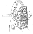
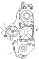
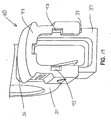
- motor assembly 10 is transversely mounted between the rearwardly located drive roller 9 and the front roller assembly 8.
- the motor output shaft which extends through an opening in gear case cover 4, ends in drive pulley 12.
- Drive pulley 12 pulls drive belt 14.
- Drive belt 14 turns driven pulley 16.
- Driven pulley 16, through gearing not shown, turns rear drive roller 9.
- a second portion of driven pulley 16 pulls dust collection fan belt 18, which powers a dust collection fan 20 that is located on an upper portion of gear case cover 4.
- fan belt 18 is an o-ring.
- the left-hand/outward side of the gear case cover 4 is covered by belt cover/housing 6, which encloses the pulleys 12 and 16 and belts 14 and 18.
- belt cover/housing 6 which encloses the pulleys 12 and 16 and belts 14 and 18.
- Completing the frame/superstructure of the sander is the right side housing 3.
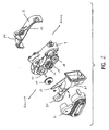
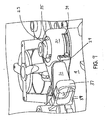
- the suction created by dust fan 20 pulls an air flow (indicated by arrows in Fig. 5) from the vicinity of drive wheel 9 through an air passage 22 cast into the right housing 3 and gear case 4.
- Upper portions of both the right housing 3 and gear case 4 define an inlet or suction chamber 24.
- the upper portion of gear case 4 also defines suction openings 26 in a trefoil arrangement.
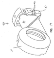
- Rotatably mounted to the upper exterior portion of gear case 4 is an inlet or suction damper 28.
- Damper 28 has trefoil openings and a user operable switch or damper 29 for rotating the damper 28 between an open or “ON” position, wherein the suction openings 26 and damper openings are aligned, and a closed or suction “OFF” position, wherein the damper is unaligned and blocks the suction openings 26.
- dust fan 20 is rotatably and coaxially mounted with damper 28 and suction openings 26.
- Dust fan 20 includes a pulley portion 23, to which fan belt 18 is drivingly connected.
- Dust fan 20 is a radial type fan. That is, rotation of dust fan 20 creates a suction at its center and a pressure around its periphery, so that airflow is from the center radially outward through the fan vanes 21 to the periphery.
- Fan enclosure 30 Mounted to the exterior of gear case 4 is fan enclosure 30 with fan 20 sandwiched in between. Fan enclosure 30 and gear case 4 define between them a fan chamber 31. Fan 20 divides fan chamber 31 into a radially inward suction/inlet chamber 32 and a radially outward discharge/outlet chamber 33. Fan enclosure 30 also defines a slot 34, through which damper switch 29 projects, and an opening 35, through which pulley portion 23 of fan 20 projects.
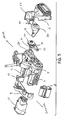
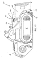
- locking collar assembly 40 comprises a collar 42 movably mounted to the exterior of duct 36. Collar 42 is movable between a first locked position, wherein it secures the inlet 61 of the dust cassette 60 to the outlet of the duct 36, and a second unlocked position, wherein the dust cassette is detachable from the outlet duct 36.
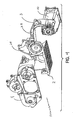
- Motor 10 drives driven pulley 12 via drive belt 14.
- driven pulley 16 drives dust fan 20 via fan belt 18.
- Rotation of dust fan 20 creates a suction that pulls air and dust from the vicinity of rear drive wheel 9 through air passage 22 and into chamber 34.
- damper 28 With damper 28 in the "ON" position, the air and dust is drawn through openings 26 and damper 28 and across fan 20.
- the air and dust is exhausted from the fan 20 through duct 36 and locking collar assembly 40 into the dust cassette 60. In the dust cassette 60 the dust is trapped while the air is filtered and exhausted across the air permeable sides.
- the user may rotate the suction damper 28 to the "OFF" position. In the OFF position the dust fan 20 will continue to turn, but will not produce a suction in the vicinity of the rear drive wheel 9.
- the user may temporarily remove belt cover 6 from gear case 4, thus exposing the belts 14 and 18.
- Fan belt 18 may be removed from driven pulley 16 and pulley portion 23 of dust fan 20. With fan belt 18 removed, the dust fan 20 will not be turned and no airflow will be produced in any portion of the dust collection path.
- seal member 27 is in the form of a flexible overmold bonded to the damper 28.
- the seal overmold 27 provides a sufficiently tight fit between enclosure 30 an damper 28 so as to limit air in leakage to the suction side of fan 20, while permitting relative rotation between damper and enclosure.
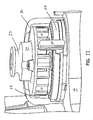
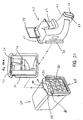
- dust cassette 60 comprises a first part 62 and a second part 64.
- First part 62 is substantially funnel shaped as it expands from a small upstream/inlet end 61, connected to the exhaust duct 36 by means of the collar assembly 40, to a larger rectangular shaped downstream end 63.
- First part 62 is preferably semi-rigid, that is slightly flexible, so that it may be deformed for ease of installation and connection.
- first part 62 may be made of Santoprene® or another rubber-like material.
- Second part 64 is an air permeable fabric skin over a rigid frame 80.
- the dust cassette 60 is substantially full of dust it can be quickly emptied by breaking the connection 66 between the first part 62 and the second part 64. Depending on the circumstances, it may first be necessary to disconnect the entire dust cassette 60 from the sander at the collar assembly 40.
- First part 62 of cassette 60 comprises a flexible clip 67 and an inlet end 61.
- flexible clip 67 hooks onto and grips a flange 7 located on the rearward end of belt cover 6.
- inlet end 61 is inserted into the locking collar assembly 40.
- the simultaneous alignment of the clip 67, flange 7, inlet end 61, and locking collar assembly 40 is made easier by the flexible material of first part 62, which the user can deform in order to make the two connections.
- Inlet end 61 includes two protruding ribs 69. With collar 42 in the second/unlocked position, inlet end 61 is fit into the collar assembly 40 so that ribs 69 are inserted through and past cutouts 43 in collar 42 and fit into recesses 38 defined in the outlet end flange 37 of the outlet duct 36. Collar 42, which slidably engages end flange 37, can then be slid down to its first position, wherein collar 42 traps ribs 69 within recesses 38, thus locking inlet end 61 in collar assembly 40. Mating detent structures 39 on flange 37 and 46 on the collar 42 restrain the collar in either of the locked or unlocked position, unless overcome by the force of the user deliberately moving the collar.
- the second part 64 of the dust cassette 60 is a dust bag/box constructed as an air permeable fabric stretched over a rigid frame 80 in the known way.
- second part 64 is substantially a rectangular solid and open at one side 65.
- frame 80 defines opposed slots 82 on opposite sides of the open end and an upper lip 84.
- the downstream end 63 of first part 62 (shown in the facing view 20A) includes a flange 70 and flexible tabs 72.
- a hook 74 is pivotably attached to first part 62 proximate to the downstream end.
- the flange 70 of first part 62 is slid into slots 82 of frame 80 of the second part 64 until open side 65 of the second part is aligned with the downstream end 63 of the first part.
- flexible tabs 72 on first part 62 will detent underneath lip 84 of the second part 64 to secure the first part and second part together. Additional security is provided by the hook 74 on first part 62, which can be pivoted to engage a latch 86 on the second part 64.
- Disconnecting of the two parts 62 and 64 is made easier by the flexible construction of the first part. After unlatching hook 74, the user can squeeze and deform first part 62 so as to undo the detent between tabs 72 and lip 84. Then flange 70 may be readily slid out of slots 82.
Landscapes
- Engineering & Computer Science (AREA)
- Mechanical Engineering (AREA)
- Grinding-Machine Dressing And Accessory Apparatuses (AREA)
- Finish Polishing, Edge Sharpening, And Grinding By Specific Grinding Devices (AREA)
Claims (11)
- Elektrisch angetriebener, handgeführter Bandschleifer mit
einem Gehäuse (4),
einem an einer ersten Stelle im Gehäuse befestigten und eine Ausgangswelle aufweisenden Motor (10),
einem Staubsammellüfter (20), der im Abstand von der Motorausgangswelle an einer zweiten Stelle im Gehäuse drehbar befestigt ist,
einer im Gehäuse befestigten Antriebsrolle (9),
einer ersten Transmission (14) zwischen der Motorausgangswelle und der Antriebsrolle und
einer zweiten Transmission zwischen der Motorausgangswelle und dem Staubsammellüfter, die einen Lüfterriemen (18) zum Antrieb des Lüfters aufweist,
dadurch gekennzeichnet, dass die zweite Transmission zur Verhinderung der Drehung des Staubsammellüfters durch Entfernen des Lüfterriemens wahlweise abtrennbar ist, ohne dass die erste Transmission zur Antriebsrolle abgetrennt wird. - Elektrisch angetriebener Bandschleifer nach Anspruch 1, bei dem die zweite Transmission ein Paar miteinander kämmender Zahnräder für den Drehantrieb des Lüfters hat.
- Elektrisch angetriebener Bandschleifer nach Anspruch 1 oder 2, ferner mit
einem vom Gehäuse gebildeten Staubströmungspfad (22) und
einem im Staubströmungspfad angeordneten und zum Blockieren des Staubströmungspfades betätigbaren Dämpfer (28). - Elektrisch angetriebener Bandschleifer nach einem der vorhergehenden Ansprüche,
bei dem die Antriebsrolle (9) eine erste Achse hat und der ferner
eine drehbar im Gehäuse befestigte und eine im Wesentlichen parallel zur ersten Achse gerichtete zweite Achse aufweisende zweite Schleifbandrolle (8) aufweist,
wobei die erste Achse und die zweite Achse in einer Ebene liegen und der Motor eine Achse hat, die im Wesentlichen parallel zur ersten Achse verläuft und in etwa in der Ebene von erster und zweiter Achse liegt. - Elektrisch angetriebener Bandschleifer nach Anspruch 3, bei dem die zweite Transmission
eine auf der Motorausgangswelle befestigte Antriebsrolle (12) und
eine am Lüfter befestigte Rolle (23) hat und
wobei der Lüfterriemen zum Antrieb die Antriebsrolle mit der Lüfterrolle verbindet. - Elektrisch angetriebener Bandschleifer nach einem der Ansprüche 1 bis 4, bei dem die zweite Transmission
eine an der Motorausgangswelle befestigte Antriebsrolle (12),
eine am Lüfter befestigte Rolle (23),
eine dritte Rolle (16) und
einen ersten Riemen (14) für eine Antriebsverbindung von der Antriebsrolle zur dritten Rolle hat und
wobei der Lüfterriemen die dritte Rolle zum Antrieb mit der Lüfterrolle verbindet. - Elektrisch angetriebener Bandschleifer nach einem der vorhergehenden Ansprüche, bei dem der Lüfter ein Radiallüfter ist.
- Elektrisch angetriebener Bandschleifer nach Anspruch 3, bei dem der Dämpfer an der Ansaugseite des Lüfters angeordnet ist.
- Elektrisch angetriebener Bandschleifer nach einem der Ansprüche 3 bis 8, ferner mit einem am Dämpfer angebrachten, flexiblen Dichtungselement (27).
- Elektrisch angetriebener Bandschleifer nach einem der Ansprüche 3 bis 9, bei dem der Dämpfer von einer ersten Stellung, in der der Staubströmungspfad blockiert ist, in eine zweite Stellung drehbar ist, in der der Staubströmungspfad nicht blockiert ist.
- Verfahren zum Unterbrechen des Staubsammelluftstroms eines elektrisch angetriebenen, handgeführten Bandschleifers gemäß einem der Ansprüche 1 bis 10, der zwischen Motorausgangswelle und Antriebsrolle (9) eine erste Transmission sowie eine zweite Transmission hat, die zwischen einer Motorausgangswelle und einem Staubsammellüfter einen Lüfterriemen (18) aufweist, gekennzeichnet durch die Schritte Abtrennen des Lüfterriemens von der zweiten Transmission durch Entfernen des Lüfterriemens ohne Abtrennen der ersten Transmission von der Antriebsrolle.
Priority Applications (2)
| Application Number | Priority Date | Filing Date | Title |
|---|---|---|---|
| EP07108263A EP1818139A1 (de) | 2003-08-29 | 2004-08-24 | Staubabsaugvorrichtung für eine Bandschleifmaschine |
| EP06114178A EP1704964B1 (de) | 2003-08-29 | 2004-08-24 | Staubabsaugvorrichtung für eine Bandschleifmaschine |
Applications Claiming Priority (2)
| Application Number | Priority Date | Filing Date | Title |
|---|---|---|---|
| US652181 | 2003-08-29 | ||
| US10/652,181 US7338348B2 (en) | 2003-08-29 | 2003-08-29 | Dust collection system for a belt sander |
Related Child Applications (1)
| Application Number | Title | Priority Date | Filing Date |
|---|---|---|---|
| EP06114178A Division EP1704964B1 (de) | 2003-08-29 | 2004-08-24 | Staubabsaugvorrichtung für eine Bandschleifmaschine |
Publications (2)
| Publication Number | Publication Date |
|---|---|
| EP1510291A1 EP1510291A1 (de) | 2005-03-02 |
| EP1510291B1 true EP1510291B1 (de) | 2007-03-28 |
Family
ID=34104743
Family Applications (3)
| Application Number | Title | Priority Date | Filing Date |
|---|---|---|---|
| EP06114178A Expired - Lifetime EP1704964B1 (de) | 2003-08-29 | 2004-08-24 | Staubabsaugvorrichtung für eine Bandschleifmaschine |
| EP07108263A Withdrawn EP1818139A1 (de) | 2003-08-29 | 2004-08-24 | Staubabsaugvorrichtung für eine Bandschleifmaschine |
| EP04020008A Expired - Lifetime EP1510291B1 (de) | 2003-08-29 | 2004-08-24 | Staubabsaugvorrichtung für eine Bandschleifmaschine |
Family Applications Before (2)
| Application Number | Title | Priority Date | Filing Date |
|---|---|---|---|
| EP06114178A Expired - Lifetime EP1704964B1 (de) | 2003-08-29 | 2004-08-24 | Staubabsaugvorrichtung für eine Bandschleifmaschine |
| EP07108263A Withdrawn EP1818139A1 (de) | 2003-08-29 | 2004-08-24 | Staubabsaugvorrichtung für eine Bandschleifmaschine |
Country Status (5)
| Country | Link |
|---|---|
| US (2) | US7338348B2 (de) |
| EP (3) | EP1704964B1 (de) |
| CN (1) | CN1600498A (de) |
| AT (2) | ATE357994T1 (de) |
| DE (2) | DE602004026638D1 (de) |
Cited By (1)
| Publication number | Priority date | Publication date | Assignee | Title |
|---|---|---|---|---|
| TWI687279B (zh) * | 2018-04-27 | 2020-03-11 | 日商日東工器股份有限公司 | 帶式研磨工具 |
Families Citing this family (22)
| Publication number | Priority date | Publication date | Assignee | Title |
|---|---|---|---|---|
| GB0318880D0 (en) * | 2003-08-12 | 2003-09-17 | Gmca Pty Ltd | Power tool and dust and debris extraction system therefor |
| US7410412B2 (en) * | 2005-01-21 | 2008-08-12 | Black & Decker Inc. | Belt sander |
| US7235005B2 (en) * | 2005-03-24 | 2007-06-26 | Black & Decker Inc. | Belt sander |
| US7846011B2 (en) * | 2005-03-24 | 2010-12-07 | Black & Decker Inc. | Belt sander |
| US8087977B2 (en) * | 2005-05-13 | 2012-01-03 | Black & Decker Inc. | Angle grinder |
| US7748381B2 (en) | 2005-12-09 | 2010-07-06 | 3M Innovative Properties Company | Portable blower system |
| DE102007017550A1 (de) | 2007-04-18 | 2008-10-23 | Robert Bosch Gmbh | Staubauffangvorrichtung |
| USD592025S1 (en) * | 2008-07-11 | 2009-05-12 | Gmca Pty Ltd. | Powered planer tool |
| WO2011119229A1 (en) * | 2010-03-24 | 2011-09-29 | C.W. Machine Worx, Ltd. | Dust suppression apparatus |
| US8800682B2 (en) * | 2010-10-01 | 2014-08-12 | Black & Decker Inc. | Dust extraction for power tools |
| US9393658B2 (en) | 2012-06-14 | 2016-07-19 | Black & Decker Inc. | Portable power tool |
| CN102922401B (zh) * | 2012-11-15 | 2016-05-11 | 陈美青 | 一种具有集尘和除尘功能的一体式抛光机 |
| EP2865487B1 (de) * | 2013-10-24 | 2016-09-14 | Siemens Aktiengesellschaft | Verfahren zum Kürzen der Laufschaufeln einer Strömungsmaschine |
| WO2017073237A1 (ja) * | 2015-10-30 | 2017-05-04 | 日立工機株式会社 | ベルトサンダ |
| SE540907C2 (en) * | 2016-11-03 | 2018-12-18 | Husqvarna Ab | A dust removal arrangement for an engine-driven tool |
| CN107253125B (zh) * | 2017-07-05 | 2019-03-22 | 东北大学 | 一种带有吸尘及减振功能的手持砂纸打磨器 |
| CN107584383B (zh) * | 2017-10-20 | 2019-08-23 | 蔡雅婷 | 一种输电线路手持式电力铁塔角钢打磨机 |
| CN110729219B (zh) * | 2019-10-25 | 2021-12-07 | 江苏佳晟精密设备科技有限公司 | 一种半导体研磨机组件 |
| US12397390B2 (en) | 2021-04-12 | 2025-08-26 | Milwaukee Electric Tool Corporation | Belt sander |
| CN114559343A (zh) * | 2022-01-26 | 2022-05-31 | 国网河南省电力公司焦作供电公司 | 电缆绝缘砂光机装置及使用方法 |
| CN114542416B (zh) * | 2022-02-23 | 2023-10-27 | 吴小龙 | 一种具有防污功能的皮带空压机 |
| CN116673832A (zh) * | 2023-06-16 | 2023-09-01 | 韶关格美机械有限公司 | 一种砂轮机 |
Family Cites Families (50)
| Publication number | Priority date | Publication date | Assignee | Title |
|---|---|---|---|---|
| US2991595A (en) | 1959-11-04 | 1961-07-11 | Millers Falls Co | Power operated belt sanding machine |
| US3180063A (en) | 1963-03-29 | 1965-04-27 | Stanley Works | Vacuum cleaning system for portable abrading machine |
| GB1058656A (en) | 1965-02-01 | 1967-02-15 | Stanley Works | Improvements in portable abrading machines |
| DE1274916C2 (de) | 1965-08-13 | 1973-05-30 | Lutz Kg Eugen | Handbandschleifmaschine mit Staubabsaugvorrichtung |
| US3391499A (en) | 1966-03-17 | 1968-07-09 | Singer Co | Dust pickup systems for portable belt sanders |
| US3566548A (en) | 1967-01-18 | 1971-03-02 | Black & Decker Mfg Co | Dust removal construction for a belt-type sander |
| US3535829A (en) | 1968-05-21 | 1970-10-27 | Singer Co | Belt cleaners for belt sanders |
| US3902284A (en) | 1974-12-17 | 1975-09-02 | Singer Co | Low profile blower assembly for portable belt sanders |
| US3938283A (en) | 1975-02-24 | 1976-02-17 | The Singer Company | Dust bag support |
| US3983664A (en) | 1975-11-21 | 1976-10-05 | Ronald Martin | Belt-type sander attachment for portable power drills |
| US4058936A (en) | 1976-01-20 | 1977-11-22 | Miksa Marton | Vacuum sander |
| DE2705388C2 (de) | 1977-02-09 | 1986-06-05 | Robert Bosch Gmbh, 7000 Stuttgart | Vorrichtung an einer Handwerkzeugmaschine zum Absaugen des Bohrkleins |
| US4192104A (en) | 1978-10-10 | 1980-03-11 | Wilderness Mold, Inc. | Dust shroud |
| US4334390A (en) | 1980-09-24 | 1982-06-15 | The Singer Company | Belt sander |
| US4381628A (en) * | 1981-07-20 | 1983-05-03 | The Singer Company | Dust control system for surface treating machine |
| US4841681A (en) * | 1983-05-27 | 1989-06-27 | Dickson Industries, Inc. | Surface blasting apparatus |
| JPS61214944A (ja) * | 1985-03-20 | 1986-09-24 | Ngk Insulators Ltd | ハニカム構造製品の移載装置 |
| JPS6234778A (ja) * | 1985-08-06 | 1987-02-14 | Niigata Eng Co Ltd | サンドブラストによる物体の加工方法 |
| GB2180783B (en) * | 1985-09-23 | 1989-09-13 | Black & Decker Inc | Improvements in or relating to power tools |
| DE3535636A1 (de) | 1985-10-05 | 1987-04-09 | Festo Kg | Transportables schleifgeraet |
| DE3542466A1 (de) | 1985-11-30 | 1987-06-04 | Licentia Gmbh | Mittels elektromotor angetriebener handhobel |
| US4758023A (en) | 1987-05-14 | 1988-07-19 | The Singer Company | Removable connection assembly |
| US4967516A (en) | 1989-12-13 | 1990-11-06 | Ryobi Motor Products Corp. | Debris collection system for a surface treating tool |
| DE4121256C2 (de) | 1991-06-27 | 1996-08-08 | Metabowerke Kg | Elektrowerkzeug mit einem Behältnis für Staub und dgl. |
| EP0558253A1 (de) | 1992-02-28 | 1993-09-01 | Black & Decker Inc. | Staubsammeln |
| US5224301A (en) | 1992-03-20 | 1993-07-06 | James Tasikas | Dual mode floor sander |
| US5237781A (en) * | 1992-03-23 | 1993-08-24 | Kris Demetrius | Hand held disc type surfacing machine |
| US5245797A (en) * | 1992-07-23 | 1993-09-21 | Milkie Terry H | Manual sander |
| JP2829224B2 (ja) * | 1992-08-14 | 1998-11-25 | リョービ モーター プロダクツ コーポレーション | 研磨装置 |
| US5518442A (en) | 1993-01-22 | 1996-05-21 | Porter-Cable Corporation | Sander |
| DE4335417B4 (de) | 1993-10-18 | 2006-11-30 | Hilti Ag | Absaugeinrichtung eines Bohr- oder Meisselgerätes |
| US5419737A (en) | 1993-10-28 | 1995-05-30 | Ryobi Motor Products Corp. | Random orbital sanding machine having a removable debris container |
| US5833524A (en) | 1994-08-22 | 1998-11-10 | Ryobi Limited | Dust collection system for a power tool |
| DE19512262C2 (de) | 1995-03-24 | 2003-07-31 | Black & Decker Inc | Handgeführter, motorgetriebener Hobel |
| US5878607A (en) | 1995-07-06 | 1999-03-09 | Johnson & Johnson Professional, Inc. | Surgical cast cutter |
| US5595531A (en) | 1995-07-26 | 1997-01-21 | Ryobi North America | Random orbit sander having speed limiter |
| US5698500A (en) | 1997-02-03 | 1997-12-16 | Uniroyal Chemical Company, Inc. | Lubricants containing ashless antiwear-dispersant additive having viscosity index improver credit |
| US5974626A (en) | 1997-03-26 | 1999-11-02 | Nilfisk-Advance, Inc. | Collection system for a floor polishing machine |
| JPH1119820A (ja) * | 1997-06-30 | 1999-01-26 | Kioritz Corp | 吸塵装置付動力切断機 |
| JP3499731B2 (ja) | 1997-10-16 | 2004-02-23 | 株式会社マキタ | 電動工具の集塵構造 |
| JPH11138435A (ja) | 1997-11-07 | 1999-05-25 | Makita Corp | 集塵装置付電動工具における集塵バッグの取付構造 |
| DE19924547A1 (de) | 1999-05-28 | 2000-11-30 | Bosch Gmbh Robert | Handwerkzeugmaschine mit Staubabsaugung |
| DE10035437A1 (de) * | 2000-07-20 | 2002-02-07 | Bosch Gmbh Robert | Staub- und Spanabtransportvorrichtung mit einer Staub- und Spanrückhaltevorrichtung |
| DE10116501A1 (de) * | 2001-04-03 | 2002-10-17 | Bosch Gmbh Robert | Stutzen zum Anschluß eines Absaugschlauchs an eine Handwerkzeugmaschine |
| GB2377164B (en) * | 2001-07-06 | 2004-12-01 | Black & Decker Inc | Airflow modification in vacuum cleaners |
| US6758731B2 (en) * | 2001-08-10 | 2004-07-06 | One World Technologies Limited | Orbital sander |
| US7124467B2 (en) * | 2002-04-08 | 2006-10-24 | Panasonic Corporation Of North America | Edge cleaning system for vacuum cleaner |
| GB0228654D0 (en) * | 2002-12-09 | 2003-01-15 | Black & Decker Inc | Planer |
| US6948412B2 (en) * | 2003-06-05 | 2005-09-27 | One World Technologies Ltd. | Motor driven wood working tool with vacuum feature |
| DE102004019155A1 (de) * | 2004-04-21 | 2005-11-10 | Robert Bosch Gmbh | Staubauffangbehälter für eine Handwerkzeugmaschine |
-
2003
- 2003-08-29 US US10/652,181 patent/US7338348B2/en not_active Expired - Fee Related
-
2004
- 2004-08-24 EP EP06114178A patent/EP1704964B1/de not_active Expired - Lifetime
- 2004-08-24 AT AT04020008T patent/ATE357994T1/de not_active IP Right Cessation
- 2004-08-24 EP EP07108263A patent/EP1818139A1/de not_active Withdrawn
- 2004-08-24 EP EP04020008A patent/EP1510291B1/de not_active Expired - Lifetime
- 2004-08-24 AT AT06114178T patent/ATE464154T1/de not_active IP Right Cessation
- 2004-08-24 DE DE602004026638T patent/DE602004026638D1/de not_active Expired - Lifetime
- 2004-08-24 DE DE602004005540T patent/DE602004005540T2/de not_active Expired - Lifetime
- 2004-08-24 CN CNA2004100644236A patent/CN1600498A/zh active Pending
-
2008
- 2008-03-03 US US12/041,202 patent/US20080153406A1/en not_active Abandoned
Cited By (1)
| Publication number | Priority date | Publication date | Assignee | Title |
|---|---|---|---|---|
| TWI687279B (zh) * | 2018-04-27 | 2020-03-11 | 日商日東工器股份有限公司 | 帶式研磨工具 |
Also Published As
| Publication number | Publication date |
|---|---|
| ATE464154T1 (de) | 2010-04-15 |
| DE602004005540D1 (de) | 2007-05-10 |
| EP1704964A3 (de) | 2006-12-13 |
| US20050048883A1 (en) | 2005-03-03 |
| EP1510291A1 (de) | 2005-03-02 |
| CN1600498A (zh) | 2005-03-30 |
| EP1818139A1 (de) | 2007-08-15 |
| US7338348B2 (en) | 2008-03-04 |
| EP1704964B1 (de) | 2010-04-14 |
| US20080153406A1 (en) | 2008-06-26 |
| DE602004026638D1 (de) | 2010-05-27 |
| EP1704964A2 (de) | 2006-09-27 |
| DE602004005540T2 (de) | 2007-12-13 |
| ATE357994T1 (de) | 2007-04-15 |
Similar Documents
| Publication | Publication Date | Title |
|---|---|---|
| EP1510291B1 (de) | Staubabsaugvorrichtung für eine Bandschleifmaschine | |
| US4381628A (en) | Dust control system for surface treating machine | |
| US4213224A (en) | By-pass type portable vacuum cleaner | |
| US5737798A (en) | Device for a vacuum cleaner and a method for cooling a motor | |
| US6442792B1 (en) | Vacuum cleaner | |
| US7363999B2 (en) | Positive air flow drive train unit for utility vehicle | |
| JP2003053654A (ja) | オービタルサンダー | |
| US6640384B2 (en) | Convertible blower and vacuum | |
| US6290761B2 (en) | Filter for vacuum cleaner | |
| EP1048258A3 (de) | Elektrisches Gebläse und damit ausgerüsteter Staubsauger | |
| AU2025275162A1 (en) | Circular saw apparatus with integrated multistage filtration system | |
| EP1321089A2 (de) | Motorgehäuse für Staubsauger | |
| JPH11236820A (ja) | 手で操縦される作業機 | |
| US7131894B1 (en) | Grinding machine with a dust collecting device | |
| JP2003274609A (ja) | 車両駆動用電動機 | |
| AU2004202624A1 (en) | Vacuum cleaner | |
| KR101346833B1 (ko) | 공기조화기 | |
| JP3193261B2 (ja) | 芝草刈機の刈芝草搬送装置 | |
| KR20010049799A (ko) | 전기 청소기 | |
| CN201101490Y (zh) | 一种干湿吸尘器 | |
| CN223492878U (zh) | 一种清洗机壳体铸件打磨装置 | |
| JP3107769B2 (ja) | Oa機器専用掃除機 | |
| JPH05184496A (ja) | 電気掃除機 | |
| JPH0947407A (ja) | 電気掃除機 | |
| KR200373454Y1 (ko) | 건식 노면 가공장치의 집진장치 |
Legal Events
| Date | Code | Title | Description |
|---|---|---|---|
| PUAI | Public reference made under article 153(3) epc to a published international application that has entered the european phase |
Free format text: ORIGINAL CODE: 0009012 |
|
| AK | Designated contracting states |
Kind code of ref document: A1 Designated state(s): AT BE BG CH CY CZ DE DK EE ES FI FR GB GR HU IE IT LI LU MC NL PL PT RO SE SI SK TR |
|
| AX | Request for extension of the european patent |
Extension state: AL HR LT LV MK |
|
| 17P | Request for examination filed |
Effective date: 20050422 |
|
| AKX | Designation fees paid |
Designated state(s): AT BE BG CH CY CZ DE DK EE ES FI FR GB GR HU IE IT LI LU MC NL PL PT RO SE SI SK TR |
|
| GRAP | Despatch of communication of intention to grant a patent |
Free format text: ORIGINAL CODE: EPIDOSNIGR1 |
|
| GRAS | Grant fee paid |
Free format text: ORIGINAL CODE: EPIDOSNIGR3 |
|
| GRAA | (expected) grant |
Free format text: ORIGINAL CODE: 0009210 |
|
| AK | Designated contracting states |
Kind code of ref document: B1 Designated state(s): AT BE BG CH CY CZ DE DK EE ES FI FR GB GR HU IE IT LI LU MC NL PL PT RO SE SI SK TR |
|
| PG25 | Lapsed in a contracting state [announced via postgrant information from national office to epo] |
Ref country code: AT Free format text: LAPSE BECAUSE OF FAILURE TO SUBMIT A TRANSLATION OF THE DESCRIPTION OR TO PAY THE FEE WITHIN THE PRESCRIBED TIME-LIMIT Effective date: 20070328 Ref country code: FI Free format text: LAPSE BECAUSE OF FAILURE TO SUBMIT A TRANSLATION OF THE DESCRIPTION OR TO PAY THE FEE WITHIN THE PRESCRIBED TIME-LIMIT Effective date: 20070328 Ref country code: BE Free format text: LAPSE BECAUSE OF FAILURE TO SUBMIT A TRANSLATION OF THE DESCRIPTION OR TO PAY THE FEE WITHIN THE PRESCRIBED TIME-LIMIT Effective date: 20070328 Ref country code: NL Free format text: LAPSE BECAUSE OF FAILURE TO SUBMIT A TRANSLATION OF THE DESCRIPTION OR TO PAY THE FEE WITHIN THE PRESCRIBED TIME-LIMIT Effective date: 20070328 Ref country code: LI Free format text: LAPSE BECAUSE OF FAILURE TO SUBMIT A TRANSLATION OF THE DESCRIPTION OR TO PAY THE FEE WITHIN THE PRESCRIBED TIME-LIMIT Effective date: 20070328 Ref country code: CH Free format text: LAPSE BECAUSE OF FAILURE TO SUBMIT A TRANSLATION OF THE DESCRIPTION OR TO PAY THE FEE WITHIN THE PRESCRIBED TIME-LIMIT Effective date: 20070328 Ref country code: SI Free format text: LAPSE BECAUSE OF FAILURE TO SUBMIT A TRANSLATION OF THE DESCRIPTION OR TO PAY THE FEE WITHIN THE PRESCRIBED TIME-LIMIT Effective date: 20070328 Ref country code: PL Free format text: LAPSE BECAUSE OF FAILURE TO SUBMIT A TRANSLATION OF THE DESCRIPTION OR TO PAY THE FEE WITHIN THE PRESCRIBED TIME-LIMIT Effective date: 20070328 |
|
| REG | Reference to a national code |
Ref country code: GB Ref legal event code: FG4D |
|
| REG | Reference to a national code |
Ref country code: CH Ref legal event code: EP |
|
| REF | Corresponds to: |
Ref document number: 602004005540 Country of ref document: DE Date of ref document: 20070510 Kind code of ref document: P |
|
| REG | Reference to a national code |
Ref country code: IE Ref legal event code: FG4D |
|
| PG25 | Lapsed in a contracting state [announced via postgrant information from national office to epo] |
Ref country code: SE Free format text: LAPSE BECAUSE OF FAILURE TO SUBMIT A TRANSLATION OF THE DESCRIPTION OR TO PAY THE FEE WITHIN THE PRESCRIBED TIME-LIMIT Effective date: 20070628 |
|
| PG25 | Lapsed in a contracting state [announced via postgrant information from national office to epo] |
Ref country code: ES Free format text: LAPSE BECAUSE OF FAILURE TO SUBMIT A TRANSLATION OF THE DESCRIPTION OR TO PAY THE FEE WITHIN THE PRESCRIBED TIME-LIMIT Effective date: 20070709 |
|
| PG25 | Lapsed in a contracting state [announced via postgrant information from national office to epo] |
Ref country code: PT Free format text: LAPSE BECAUSE OF FAILURE TO SUBMIT A TRANSLATION OF THE DESCRIPTION OR TO PAY THE FEE WITHIN THE PRESCRIBED TIME-LIMIT Effective date: 20070828 |
|
| ET | Fr: translation filed | ||
| REG | Reference to a national code |
Ref country code: CH Ref legal event code: PL |
|
| NLV1 | Nl: lapsed or annulled due to failure to fulfill the requirements of art. 29p and 29m of the patents act | ||
| PG25 | Lapsed in a contracting state [announced via postgrant information from national office to epo] |
Ref country code: SK Free format text: LAPSE BECAUSE OF FAILURE TO SUBMIT A TRANSLATION OF THE DESCRIPTION OR TO PAY THE FEE WITHIN THE PRESCRIBED TIME-LIMIT Effective date: 20070328 |
|
| PG25 | Lapsed in a contracting state [announced via postgrant information from national office to epo] |
Ref country code: RO Free format text: LAPSE BECAUSE OF FAILURE TO SUBMIT A TRANSLATION OF THE DESCRIPTION OR TO PAY THE FEE WITHIN THE PRESCRIBED TIME-LIMIT Effective date: 20070328 Ref country code: CZ Free format text: LAPSE BECAUSE OF FAILURE TO SUBMIT A TRANSLATION OF THE DESCRIPTION OR TO PAY THE FEE WITHIN THE PRESCRIBED TIME-LIMIT Effective date: 20070328 |
|
| PG25 | Lapsed in a contracting state [announced via postgrant information from national office to epo] |
Ref country code: DK Free format text: LAPSE BECAUSE OF FAILURE TO SUBMIT A TRANSLATION OF THE DESCRIPTION OR TO PAY THE FEE WITHIN THE PRESCRIBED TIME-LIMIT Effective date: 20070328 |
|
| PLBE | No opposition filed within time limit |
Free format text: ORIGINAL CODE: 0009261 |
|
| STAA | Information on the status of an ep patent application or granted ep patent |
Free format text: STATUS: NO OPPOSITION FILED WITHIN TIME LIMIT |
|
| 26N | No opposition filed |
Effective date: 20080102 |
|
| PG25 | Lapsed in a contracting state [announced via postgrant information from national office to epo] |
Ref country code: MC Free format text: LAPSE BECAUSE OF NON-PAYMENT OF DUE FEES Effective date: 20070831 Ref country code: IT Free format text: LAPSE BECAUSE OF FAILURE TO SUBMIT A TRANSLATION OF THE DESCRIPTION OR TO PAY THE FEE WITHIN THE PRESCRIBED TIME-LIMIT Effective date: 20070328 Ref country code: GR Free format text: LAPSE BECAUSE OF FAILURE TO SUBMIT A TRANSLATION OF THE DESCRIPTION OR TO PAY THE FEE WITHIN THE PRESCRIBED TIME-LIMIT Effective date: 20070629 |
|
| PG25 | Lapsed in a contracting state [announced via postgrant information from national office to epo] |
Ref country code: IE Free format text: LAPSE BECAUSE OF NON-PAYMENT OF DUE FEES Effective date: 20070824 |
|
| PG25 | Lapsed in a contracting state [announced via postgrant information from national office to epo] |
Ref country code: EE Free format text: LAPSE BECAUSE OF FAILURE TO SUBMIT A TRANSLATION OF THE DESCRIPTION OR TO PAY THE FEE WITHIN THE PRESCRIBED TIME-LIMIT Effective date: 20070328 |
|
| PG25 | Lapsed in a contracting state [announced via postgrant information from national office to epo] |
Ref country code: CY Free format text: LAPSE BECAUSE OF FAILURE TO SUBMIT A TRANSLATION OF THE DESCRIPTION OR TO PAY THE FEE WITHIN THE PRESCRIBED TIME-LIMIT Effective date: 20070328 |
|
| PG25 | Lapsed in a contracting state [announced via postgrant information from national office to epo] |
Ref country code: BG Free format text: LAPSE BECAUSE OF FAILURE TO SUBMIT A TRANSLATION OF THE DESCRIPTION OR TO PAY THE FEE WITHIN THE PRESCRIBED TIME-LIMIT Effective date: 20070628 Ref country code: LU Free format text: LAPSE BECAUSE OF NON-PAYMENT OF DUE FEES Effective date: 20070824 |
|
| PG25 | Lapsed in a contracting state [announced via postgrant information from national office to epo] |
Ref country code: HU Free format text: LAPSE BECAUSE OF FAILURE TO SUBMIT A TRANSLATION OF THE DESCRIPTION OR TO PAY THE FEE WITHIN THE PRESCRIBED TIME-LIMIT Effective date: 20070929 Ref country code: TR Free format text: LAPSE BECAUSE OF FAILURE TO SUBMIT A TRANSLATION OF THE DESCRIPTION OR TO PAY THE FEE WITHIN THE PRESCRIBED TIME-LIMIT Effective date: 20070328 |
|
| PGFP | Annual fee paid to national office [announced via postgrant information from national office to epo] |
Ref country code: FR Payment date: 20110830 Year of fee payment: 8 |
|
| REG | Reference to a national code |
Ref country code: FR Ref legal event code: ST Effective date: 20130430 |
|
| PG25 | Lapsed in a contracting state [announced via postgrant information from national office to epo] |
Ref country code: FR Free format text: LAPSE BECAUSE OF NON-PAYMENT OF DUE FEES Effective date: 20120831 |
|
| PGFP | Annual fee paid to national office [announced via postgrant information from national office to epo] |
Ref country code: DE Payment date: 20170815 Year of fee payment: 14 Ref country code: GB Payment date: 20170823 Year of fee payment: 14 |
|
| REG | Reference to a national code |
Ref country code: DE Ref legal event code: R119 Ref document number: 602004005540 Country of ref document: DE |
|
| GBPC | Gb: european patent ceased through non-payment of renewal fee |
Effective date: 20180824 |
|
| PG25 | Lapsed in a contracting state [announced via postgrant information from national office to epo] |
Ref country code: DE Free format text: LAPSE BECAUSE OF NON-PAYMENT OF DUE FEES Effective date: 20190301 |
|
| PG25 | Lapsed in a contracting state [announced via postgrant information from national office to epo] |
Ref country code: GB Free format text: LAPSE BECAUSE OF NON-PAYMENT OF DUE FEES Effective date: 20180824 |