EP1510142B1 - Manipulation d'articles en forme de tige de l'industrie du tabac - Google Patents
Manipulation d'articles en forme de tige de l'industrie du tabac Download PDFInfo
- Publication number
- EP1510142B1 EP1510142B1 EP04019464A EP04019464A EP1510142B1 EP 1510142 B1 EP1510142 B1 EP 1510142B1 EP 04019464 A EP04019464 A EP 04019464A EP 04019464 A EP04019464 A EP 04019464A EP 1510142 B1 EP1510142 B1 EP 1510142B1
- Authority
- EP
- European Patent Office
- Prior art keywords
- processing
- drum
- articles
- conveyor
- transfer conveyor
- Prior art date
- Legal status (The legal status is an assumption and is not a legal conclusion. Google has not performed a legal analysis and makes no representation as to the accuracy of the status listed.)
- Not-in-force
Links
Images


Classifications
-
- A—HUMAN NECESSITIES
- A24—TOBACCO; CIGARS; CIGARETTES; SIMULATED SMOKING DEVICES; SMOKERS' REQUISITES
- A24C—MACHINES FOR MAKING CIGARS OR CIGARETTES
- A24C5/00—Making cigarettes; Making tipping materials for, or attaching filters or mouthpieces to, cigars or cigarettes
- A24C5/60—Final treatment of cigarettes, e.g. marking, printing, branding, decorating
- A24C5/606—Perforating cigarettes
-
- A—HUMAN NECESSITIES
- A24—TOBACCO; CIGARS; CIGARETTES; SIMULATED SMOKING DEVICES; SMOKERS' REQUISITES
- A24C—MACHINES FOR MAKING CIGARS OR CIGARETTES
- A24C5/00—Making cigarettes; Making tipping materials for, or attaching filters or mouthpieces to, cigars or cigarettes
- A24C5/47—Attaching filters or mouthpieces to cigars or cigarettes, e.g. inserting filters into cigarettes or their mouthpieces
- A24C5/478—Transport means for filter- or cigarette-rods in view of their assembling
Definitions
- the invention relates to a method for processing rod-shaped articles of the tobacco-processing industry, in which the articles are provided on a transfer conveyor are transferred from the transfer conveyor to at least one processing drum for processing the articles, and during a taking place by the processing drum promotion of Articles are edited.
- the invention further relates to a device for processing rod-shaped articles of the tobacco-processing industry, with a transfer conveyor for receiving the articles, and with at least one processing drum associated with the transfer conveyor for Removing the articles from the transfer conveyor and processing the articles during conveyance of the articles by the processing drum.
- cigarettes Under rod-shaped articles of the tobacco-processing industry are here in particular cigarettes, cigarette filters or tobacco sticks for cigarettes, for example. Tobacco sticks from cut tobacco, understood.
- FIG. 1 shows the EP 0 432 663 B1 a device for perforating filter cigarettes.
- the filter cigarettes are conveyed along a feed drum to a first transfer drum.
- a portion of the cigarettes on the transfer drum is transferred from the transfer drum to a first perforating drum and conveyed after perforation to a first discharge drum.
- the remainder of the cigarettes is dispensed from the first transfer drum to a second transfer drum, conveyed to a second perforating drum, and after perforation delivered from the second perforating drum to a second delivery drum which transfers the cigarettes to the first delivery drum.
- the WO 03/043449 A1 in turn shows a Filteransetzmaschine, which consists of a main drum and several other associated drums.
- a Filteransetzmaschine which consists of a main drum and several other associated drums.
- With the help of a pick-up drum are moved from each other moved parts with inserted filter piece for attaching a tipping paper to the outside of the main drum, connected to each other and returned with the help of a return drum as one-piece cigarette units back to the main drum.
- the object of the present invention is to improve the state of the art.
- An important advantage of the present invention is that, contrary to the prior art, to feed the articles to the processing drum and to remove the articles from the processing drum, only a single transfer conveyor is needed instead of four different drums.
- the invention includes the recognition that the preferably designed as a transfer drum transfer conveyor does not necessarily have to be fully occupied with articles. Rather, the items can be stored in any transfer conveyor only at certain points on the transfer conveyor, while other places remain free. In this way, the free points of the transfer conveyor can be used to cancel the articles processed by the processing drum.
- Machining of articles means here an effect on the appearance, the structure or the function of the article, in particular a cutting, a perforating, a rewinding of the article with a tipping paper leaflet or a printing on the article.
- the article is placed on the processing drum between a take-off position where the processing drum removes the articles from the transfer conveyor and a discharge position at which the processing drum returns the articles to the transfer conveyor on the processing drum by at least about 360 ° promoted. In this way, the processed article returns to the transfer conveyor and can be stored on a free position on the transfer conveyor.
- the processing drum is preferably rotated by at least about 360 ° plus a circumferential length of the article.
- the article can be rolled back on the peripheral surface of the processing drum. This preferably by at least about 360 ° about its own axis running roles of the article allows, for example, to perforate the articles on the processing drum on its entire circumference.
- a roll block associated with the processing drum may be used to roll the articles in the receptacles on the processing drum.
- the roller block whose axis of rotation is preferably parallel to the axis of rotation of the processing drum and whose smallest distance from the processing drum is preferably slightly smaller than the diameter of the article, is preferably associated with a laser assembly, the articles through a corresponding recess in the roller block and / or on the roller block passed through during the rolling of the articles through the roller block.
- An embodiment of the invention has on the transfer conveyor an even number of in the conveying direction at a certain distance from each other arranged receptacles for the article on and on the processing drum also an even number of processing recordings for the article.
- the machining receptacles on the processing drum are designed such that in them articles of the roller block by an odd multiple of, measured in the conveying direction, preferably at least one third of the circumference of the article amount, distance of the recordings on the transfer conveyor are rollable. In this way let the rolled and possibly perforated articles after rolling in an unoccupied recording of the transfer conveyor cover and pass from this, for example, to a secondary drum.
- the articles are removed by the processing drum from the transfer conveyor at a distance from each other in the conveying direction, which is greater than or equal to the circumference of the article.
- the articles on the processing drum can easily be rolled around its own axis by at least about 360 ° and optionally perforated on its entire circumference during the rotation.
- the articles on the transfer conveyor are preferably provided such that they have a distance from each other, which is preferably greater than or equal to four-thirds of the circumference of the articles divided by the number of processing drums.
- Another important advantage of the invention is that several transfer drums can be assigned to the transfer conveyor.
- an article can be made available in every second receptacle on the transfer conveyor, the articles being delivered alternately to two structurally identical processing drums arranged next to one another.
- the processing drum is associated with the transfer conveyor in a manner known to those skilled in the art, and in particular adapted in terms of their circumference and rotational speed and the transfer conveyor adapted to take over the article from the transfer conveyor in a desired manner according to the invention.
- the transfer conveyor is preferably also designed as a drum, which preferably as receiving for the article to the conveying direction laterally extending, preferably at a distance of at least one third of the circumference of the article spaced apart in the conveying direction troughs.
- the processing of the articles according to the above-mentioned embodiments is not limited to the perforation of the articles. Rather, it is also possible with the above-described embodiments, to roll over the articles during their stay on the processing drum with a covering sheet. In this case, it is possible to carry out the supply of the covering sheets and the rewinding of the articles with the lining sheets on the processing drum itself or to provide further drums, which in turn are connected to the processing drum.
- the respective processing can be taken out of the actual production chain by the processing drum according to the invention.
- the processing eg perforation or rewinding with covering sheets, can thus be connected to each production chain as a so-called stitching method.
- the articles are, for example, according to the above-outlined preferred Embodiments taken from the material flow or the production chain with the help of the processing drum, then, for example, perforated or rolled over with covering sheets, and finally fed back into the production process of the same processing drum.
- the functional units delivering this rewinder preferably a removal of the actual rolling process from the transport chain of the corresponding Filteransetzmaschine.
- the article components tobacco rods, double filters and tipping paper are preferably transported until the rolling process.
- the actual rolling process then takes place on a drum branch, which is branched off from the production chain.
- the roll Similar to the perforation of articles, the roll not only rolls over the tobacco rod filter tobacco rod group with the pad, but also returns it by a certain amount against the conveying direction on the drum periphery. In this way, the finished double-filter cigarettes rolled over with tiling paper can be fed back to the actual transport chain of the filter attachment machine via the same drums of the branched-off drum branch.
- the drum branch is not limited to a processing drum. Rather, it is possible to use any number of processing drums in such a drum branch.
- the aforementioned intermediate conveyors can also be used to supply parts of the desired article to them.
- this is further developed such that the machining conveyor formed a roll of two conveyor belts, an article from the transfer conveyor and taking over the roll channel donating first conveyor drum, the articles of the rolling channel decreasing second conveyor drum, and one Article of the second conveyor drum has decreasing and delivering to the first conveyor drum third conveyor drum, wherein the articles are offset by means of the rolling channel upstream so that they can be set by the third conveyor drum in unoccupied recordings of the first conveyor drum, so that they from the first conveyor drum of the processing conveyor can be returned directly into unoccupied recordings of the transfer conveyor or at least one intermediate conveyor in unoccupied recordings of the transfer conveyor.
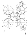
- FIG. 1 1 shows a first embodiment 1 of a device according to the invention for processing cigarettes 2.
- the device 1 has a feed conveyor 4 designed as a feed conveyor for feeding the articles.
- the feed drum 4 rotates according to arrow 6 about a rotation axis 8 in the counterclockwise direction and conveys the article 2 in non-illustrated, formed laterally to the conveying direction of the feed drum 4 in the peripheral surface 10 wells.
- the troughs have a distance in the conveying direction, which corresponds to at least twice the diameter of the article 2.
- Adjacent to the feed drum 4 serving as a transfer conveyor transfer drum 12 is arranged.
- the transfer drum 12 rotates about a parallel to the axis of rotation 8 of the feed drum 4 arranged rotational axis 14 as indicated by arrow 16 in a clockwise direction at the same peripheral speed as the feed drum 4.
- the distance between the axes of rotation 8 and 14 is such that a trouble-free transfer of the article 2 guaranteed is.
- the transfer drum 12 has as receptacles for the article 2 also formed laterally to the conveying direction in its peripheral surface 18 wells 20.
- the troughs 20 are arranged in the conveying direction at a distance from each other on the transfer drum 12, which corresponds to half the distance of the troughs on the feed drum 4.
- a first processing drum 22 Adjacent to the transfer drum 12, a first processing drum 22 is arranged.
- the machining drum 22 rotates according to arrow 24 about a rotation axis 26.
- the rotation axis 26 is parallel to the rotation axis 14 of the transfer drum 12.
- the distance of the rotation axes 26 and 14 is dimensioned so that a trouble-free transfer of the article is guaranteed.
- extended troughs 30 for receiving the articles 2 are provided in the conveying direction.
- the troughs 30 are bounded by webs 32 formed laterally to the conveying direction.
- the distance of the webs 32 corresponds to four times the distance of the troughs 20 on the transfer drum 12.
- the dimension of the troughs 30 is such that the articles 2 can be offset (rolled) in the troughs 30 by a distance three times the distance the troughs 20 on the transfer drum 12 corresponds.
- the first processing drum 22 is associated with a roller block 34 with a rolling surface 36.
- the roller block 34 rotates at the same peripheral speed as the processing drum 22 about a parallel to the rotation axis 26 of the processing drum 22 arranged rotation axis counterclockwise.
- a laser 38 emits a laser beam 40 serving for perforation of the article 2 perpendicular to the peripheral surface 28 of the processing drum 22.
- the laser beam 40 is focused onto the peripheral surfaces 44 of the articles 2 by means of a focusing lens 42.
- the articles 2 are offset by rolling between the machining drum 22 and the roller block 34 opposite to the direction of rotation of the machining drum 22.
- a second processing drum 52 Downstream of the transfer drum 12, a second processing drum 52 is arranged.
- the second processing drum 52 is identical to the first processing drum 22.
- the same parts are designated by reference numerals, which are compared to the reference numerals of the first processing drum 22 and its associated parts roller block 34 and laser 38 but increased by the number 30.
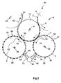
- FIG. 2 shows a second embodiment 90 of a device according to the invention.
- the device 90 is identical to the device 1 with the only difference that not two lasers 38 and 68, but only a laser 92 is provided, whose light is divided by means of a beam splitter, not shown in the laser beams 40 and 70, respectively.
- the removal drum 80 rotates according to arrow 82 in the counterclockwise direction about a rotation axis 84.
- the rotation axis 84 is parallel to the rotation axis 14 of the transfer drum 12.
- the discharge drum 80 corresponds to the Zu concepttrommel 4. Just like the Zu concepttrommel 4 and the discharge drum 80 is disposed adjacent to the transfer drum 12 such that a trouble-free transfer of the article 2 is guaranteed.
- the transfer drum 12 conveys the articles 2 further in the conveying direction 16 to the first processing drum 22.
- the first processing drum 22 only removes every second article 2 from the transfer drum 12, since the depressions 30 of the first processing drum 22 are spaced from one another in the conveying direction 24. which corresponds to four times the trough distance on the transfer drum 12.
- the articles 2 As soon as the articles 2 come into contact with the circumferential surface 36 of the roller block 34, the articles 2, viewed in the conveying direction 24, are rolled back into the troughs 30 on the web 32 lying behind them.
- the articles 2 are at least once completely rotated about its axis and thereby offset by three times the trough spacing on the transfer drum 12 in the troughs 30.
- the articles 2 are perforated on their circumferential surface 44 with the preferably pulsed laser beam 40, so that a full circumferential perforation of the peripheral surface 44 of the articles 2 takes place during the backward rolling of the article 2 in the troughs 30 of the processing drum 22.
- the so perforated article 2, which in the FIG. 1 lighter than the unperforated article 2 are shown, are then further promoted by the processing drum 22 along the direction of rotation 24 until they have been promoted over a decrease position 31 by more than 360 ° about the axis of rotation 26 so that they reach a dispensing position 33.
- positions 31 and 33 are identical.
- the perforated articles 2 are thereby offset from the troughs 20 of the transfer drum 12, from which the processing drum 22 has removed the articles 2, by three troughs.
- the perforated article 2 is then removed from the processing drum 22 from the position 33 by means of the transfer drum 12 and conveyed further in the conveying direction 16 of the transfer drum 12 in the direction of the second processing drum 52. However, this does not remove the already perforated article 2 from the transfer drum 12, so that it is further promoted by the transfer drum 12 and finally reaches the discharge drum 80, which is identical to the feed drum 4 and the perforated article 2 decreases from the transfer drum 12 and ab responsiblet.
- the articles 2 not removed from the transfer drum 12 by the first processing drum 22 pass to the second processing drum 52 as indicated by the dark hatched articles 2 in FIG FIG. 1 indicated downstream of the first processing drum 22 on the transfer drum 12.
- the second processing drum 52 takes the perforating in the FIG. 1 dark hatched article 2 in an identical manner from the transfer drum 12, as in the first processing drum 22 happens. Also, the subsequent rolling and perforating of the article 2 fully corresponds to the procedure described above with respect to the first processing drum 22. The same applies to the return of the perforated article to the transfer drum 12 and the subsequent removal of the perforated article through the removal drum 80th
- FIG. 3 shows a third embodiment 100 of a device according to the invention.
- the in the FIG. 3 shown device parts of the device 100 are not different from the corresponding device parts of the device 1 of FIG. 1 , They are therefore denoted by the same reference numerals. Only in operation does the device 100 differ from the device 1 as follows:
- article 2 is supplied to the transfer drum 12 only at every second position. Thus, 20 articles 2 are provided on the transfer drum 12 only on every fourth trough. It is therefore sufficient to use the first processing drum 22 for rolling and perforating the article 2.
- On the second processing drum 52 in the embodiment 100 of the FIG. 3 be waived.
- the second processing drum 52 is in the FIG. 3 therefore omitted.
- Embodiment 100 therefore, illustrates one of the key advantages of the present invention. Because the invention can respond flexibly to an increase or decrease in the throughput of a cigarette making machine. Depending on the number of articles 2 supplied with the feed drum 4, the second processing drum 52 may be provided or omitted.
- the first processing drum 22 may be omitted if no perforation of the articles is desired.
- the articles are then simply unchanged with the transfer drum 12 of the Feeding drum 4 conveyed to the discharge drum 80.
- This too is a decisive advantage over the prior art.
- Even if the article were not perforated it would be necessary to promote the articles over all the drums which normally serve for rolling or perforation. This results in the prior art, a large time and loss of throughput and an increased space requirement, while in the present invention can be dispensed with any processing drum, which is not needed.
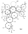
- FIG. 4 shows a schematic representation of a fourth embodiment 104 of a device according to the invention for processing (in the FIG. 4 not shown) cigarettes.
- FIG. 4 shows a production chain of drums of a filter attachment machine, not shown. From this drum chain branches in the FIG. 4 down substantially vertically two processing branches 108 and 110 for processing cigarettes. The respective filters are fed via substantially vertically upwardly branching filter feed branches 112 and 114.
- it is possible to arbitrarily add or omit each of the branches 108, 110, 112 and 114, or to turn it on or off. Because by turning on or off or adding or omitting one of the branches 108, 110, 112 and 114, the actual material chain 106 remains unaffected.
- the filters which are enveloped in the branch 108 are supplied by the branch 112, while the filters wrapped in branch 110 are fed into branch 114.
- the drums in the device 104 are driven, formed and matched in the usual manner in filter tipping machines.
- the two branches 108 and 110 are supplied to the production chain 106 in the device 104 via a supply branch 116 and 118, respectively.
- the branch 116 serves the branch 108, while the branch 118 supplies the branch 110.
- this can also be done the other way round.
- one of the branches 116 or 118 may be omitted or one of these branches may be turned off without bringing the device 104 to a standstill.
- the branches 116 and 118 can thus be operated or switched on and off completely independently of each other, just like the branches 108 and 110.
- the core of the material-carrying drum chain 106 is formed by drums 120, 122, 124, 126, 128, 130, 132, 134 and 136 arranged essentially linearly one behind the other.
- the material flow in the FIG. 4 goes from the drum 120 to the drum 136.
- the finished double filter cigarettes are finally taken at the end of the device 104 in a conventional manner in filter tipping machine from a non-illustrated drum, a Not shown cutting device cut into individual cigarettes, but not shown, for example, as in Fig.
- the first drum 120 of the chain 106 is fed tobacco double sticks from both the feed branch 116 and the feed branch 118.
- the branch 116 takes over for this purpose by means of a drum 140 tobacco double sticks from a single or a two-lane cigarette machine and passes them to a drum 142 on.
- the double stick is then cut on the drum 142 by means of a cutter 144 and then transferred in a cut form to a spreading drum 146.
- the individual sticks of the tobacco double stick are laterally separated from each other in the direction of movement in order to be able to place the double filter between them in the later course.
- tobacco double sticks are fed to the drum 120 in the branch 118 of drums 140a, 142a, 146a and a cutter 144a.
- the drum 120 On the drum 120 are thus two families of cut and spread tobacco double sticks. One family is from the feed drum 140, while the other comes from the feed drum 140a. The drum 120 must therefore be provided with corresponding receptacles in order to be able to receive all the double sticks from the feed drums 146 and 146a. These are then passed from the drum 120 to the drum 122.
- the Drum 122 serves as a distributor drum. Because it is from the drum 122 in the in the FIG. 4 In the apparatus 104 shown in FIG. 10, the double sticks originating from the feed drum 140 are transferred to the branch 108, while the double sticks originating from the feed drum 140a are forwarded to the drum 124 following in the chain 106, in order to be subsequently processed in the branch 110.
- the drum 124 in the illustrated embodiment serves not only to forward the double sticks of the feed drum 140a, but also to introduce double filters, which takes the drum 124 from a filter feed drum 148 of the filter feed branch 112.
- the filter feed drum 148 receives the filter from further filter feed drums, not shown, which in turn receive the filters from a non-illustrated, conventional filter production.
- the drum 124 feeds the double filters to the drum 122 in such a manner that they come to lie double filters between the double sticks obtained from the feeding drum 140.
- the drum 122 then feeds the tobacco rod filter tobacco rod groups into the branch 108.
- the branch 108 has for this purpose a first intermediate conveyor drum 150 for removing the groups from the drum 122 and a second intermediate conveyor drum 152 for removing the groups from the drum 150.
- the drum 152 serves to adhere the pads removed from an endless tipping paper strip 154 by means of a cutting drum 156 by means of a tipping applicator drum 158 to the tobacco rod filter tobacco rod groups obtained from the drum 150.
- the tobacco rod filter tobacco rod groups provided in this way with pad flakes are then delivered from the drum 152 to the processing drum 160 according to the invention.
- the tobacco rod filter tobacco rod groups with the attached to them Tufing paper is rolled over with the aid of a roller block 162. As a result of this rolling, the double cigarette then finished is set against the conveying direction to the rear in a free recess of the drum 160 provided for this purpose.
- the drum 160 is able to place the finished articles in corresponding free depressions of the drum 152, which in turn deposits the finished articles in free troughs of the drum 150 provided for this purpose, which in turn provide the articles in the process free troughs of the drum 122 stores.
- the finished double cigarettes are then delivered to the intended for further transport drum 124.
- the drum 124 then forwards the double sticks obtained from the feed conveyor drum 140a and the finished double filter cigarettes obtained from the working drum 160 to an intermediate feed drum 126, and this in turn to a intermediate feed drum 128 and this in turn to the drum 130.
- the drum 130 has the same function as the drum 122. This means that the drum 130 delivers the finished double filter cigarettes obtained from the drum 160 to a discharge drum 132 which delivers the finished double filter cigarettes to a intermediate conveyor drum 134 and this in turn to a intermediate conveyor drum 136, which then emits this according to arrow 138 for further processing.
- drum 130 receives, via drum 132, a filter feed drum 161 of branch 114 for the spread double-tipped sticks of feed drum 140a. Subsequently, the thus-filtered tobacco rod filter tobacco groups of the drum 130 in the manner described with respect to the drum 122 to an intermediate conveyor drum 150a, therefrom to a second intermediate conveyor drum 152a, on the second intermediate conveyor drum 152a by means of a padded lamina cut from an endless tipping paper strip 154a by a cutting drum 156a therefor which is attached to the tobacco rod filter tobacco rod groups by a plaque applying drum 158a, provided with padding sheets and finally rolled over with these pad sheets on a processing drum 160a according to the invention by means of an end roller block 162a. Also, the return of the finished double filter cigarettes to the drum 130, as in the manner described with respect to the branch 108, also occurs in the branch 110 in question here.
- FIG. 5 shows a section of the device 104 of FIG. 4 in an enlarged view.
- the branch 108 of the device 104 together with the drums arranged in the vicinity of the branch 108, is shown enlarged.
- FIG. 5 serves to illustrate the flow of double sticks 166 originating from branch 116 in comparison with double sticks 168 originating from branch 118 FIG. 5
- the double sticks 166 are shown as hollow circles with a horizontal diagonal, while the double sticks 168 are shown as hollow circles with an oblique diagonal in order to distinguish the double sticks 166 from the double sticks 168.
- the drum 146 carries a double stick 166 only in every third tray.
- the drum 146a carries a double stick 168 only in every third tray.
- the drums 146 and 146a as well as the others in the Figs FIG. 5 Drums shown are the directions of rotation of the drums symbolized by curved arrows attached in the drums.
- the drums 146 and 146a sequentially deposit their double sticks 166 and 168, respectively, after the spreading carried out on these drums, onto the downstream feed drum 120 provided with corresponding depressions.
- the feed drum 120 then delivers both tobacco double sticks 166 and 168 to the drum 122.
- the drum 122 directly discharges the double sticks 168 originating from the branch 118 to a downstream conveying drum 124.
- the double sticks 168 thus removed are then moved according to FIG. 4 delivered to the further drum 126 and supplied to the next processing branch 110.
- the double sticks 166 originating from the branch 116 are transferred from the drum 122 to the intermediate drum 150 of the branch 108 after having received a double filter 170 fed from the filter feed drum 148 of the filter feed branch 112 via the drum 124.
- the thus provided with a double filter 170 tobacco rod filter tobacco groups are from this date in the FIG. 5 represented as hollow circles with two vertically crossed diagonals and designated as groups 172.
- the groups 172 are then transferred to a further intermediate conveyor drum 152, provided there by a drum 158 with a covering sheet 174 and then rolled over with the aid of a roll block 162 on a drum 160 with the lining sheet 174.
- the thus-finished product of the double-filter cigarette passes around a depression counter to the conveying direction of the drum 160 to the rear, as indicated by the arrow 176.
- the thus finished double filter cigarette is in the FIG. 5 shown as a black circle and provided with the reference numeral 178.
- pitch offset of the finished product 178 is a return transport of the finished double filter cigarette 178 with the help of the corresponding free troughs holding drums 152, 150 and 122 possible.
- the drum 122 then delivers the finished double filter cigarettes 178 to the drum 124, which forwards them toward the drum 126. From the drum 126, the finished products 178 are then as already explained above for further processing on the drums 128, 130, 132 134, 136 to the further processing according to arrow 138 of FIG. 4 forwarded.
- the drum 124 has for this purpose corresponding wells that can accommodate the finished products 178.
- FIG. 5 shows with dashed lines indicated drums further, otherwise not further executed embodiments.
- a drum 150a ' may be provided. This means that the branch 110 can also be attached directly to the drum 122.
- the filter branch 114 could then supply the filters for the second double sticks 168, for example, by means of a drum 161 'shown in dashed lines.
- FIG. 6 shows a part of the branch 108 in a further enlarged view.
- the FIG. 6 shows in particular about the FIG. 5
- the respective position changes of the finished double filter cigarettes 178 from the drum 160 to the drum 152 and from there to the drum 150 or the groups 172 of the drum 150 on the drum 152 and from there to the drum 160th
- FIG. 7 shows a fifth embodiment of the invention.
- the rollover of the tobacco rod filter tobacco rod groups 172 is carried out not by means of a roller block 162 but by means of a belt roll.
- the band rolling will be described in more detail below.
- the tobacco rod filter tobacco rod groups 172 are shown as solid black circles, while the finished double filter cigarettes 178 are shown as hollow circles.
- the FIG. 7 illustrated embodiment however, as the embodiment of the FIGS. 4 to 6 ,
- the band roll of the FIG. 7 works as follows:
- the processing drum 160 is that in the FIGS. 4 to 6 illustrated embodiment replaced by a processing conveyor with three a rolling channel 180 having conveyor drums 182, 184 and 186th
- the rolling channel 180 is formed on the drum side by a roller belt 188, which is guided in not shown grooves in the drums 182 and 184 and 186 and driven by a drive 190 around the drums 182 and 184 circumferentially in the conveying direction of the tobacco rod filter tobacco rod groups 172 becomes.
- the rolling channel 180 is formed by a second roller belt 196 revolving around drums 192 and 194.
- the speed of the first roll band 188 differs from that of the second roll band 196, so that the tobacco filter tobacco rod groups 172 rotate in the rolling channel 180, so that the Tobacco rod filter tobacco rod groups 172 are wrapped in the roll channel 180 with the tipping paper 174 and leave the rolling channel 180 as finished double filter cigarettes 178.
- the drum 182 serves to introduce the tobacco rod filter tobacco rod groups 172 directly into the rolling channel 180, while the drum 184 serves to remove the finished double filter cigarettes 178 directly from the rolling channel 180.
- the drum 184 then transfers the finished double filter cigarettes 178 to the intermediate drum 186, which in turn returns it to the drum 182. In the same way as by the roll with the help of the roller block 176 in the in FIGS.
- the rolling of the tobacco rod filter tobacco rod groups 172 in the rolling channel 180 causes a slowing of the tobacco rod filter tobacco rod groups 172 which causes the tobacco rod filter tobacco rod groups 172 to pass through the drums after being returned as finished double filter cigarettes 178 184 and 186 come to lie in free troughs of the drum 182 which are upstream of the troughs used to feed the tobacco rod filter tobacco rod groups 172 to the rolling channel 180.
Landscapes
- Manufacturing Of Cigar And Cigarette Tobacco (AREA)
Claims (23)
- Procédé de traitement d'articles en forme de bâtonnet (2, 166, 168, 170, 172, 178) de l'industrie de transformation du tabac, comportant les étapes suivantes :les articles (2, 166, 168, 170, 172, 178) sont mis à disposition sur un convoyeur de transfert (12, 122, 130),les articles (2, 166, 168, 170, 172, 178) sont transférés du convoyeur de transfert (12, 122, 130) vers au moins un convoyeur de traitement (180, 182, 184, 186, 188, 196) pour le traitement des articles (2, 166, 168, 170, 172, 178),les articles (2, 166, 168, 170, 172, 178) sont traités pendant un déplacement qui est réalisé par le convoyeur de traitement (180, 182, 184, 186, 188, 196),caractérisé en ce que les articles (2, 166, 168, 170, 172, 178), après le traitement, sont remis du convoyeur de traitement (180, 182, 184, 186, 188, 196) sur le convoyeur de transfert (12, 122, 130), les articles (2, 166, 168, 170, 172, 178) étant roulés et/ou perforés pendant le déplacement sur le convoyeur de traitement (22, 52, 160).
- Procédé selon la revendication 1, dans lequel le convoyeur de traitement est un tambour de traitement (22, 52, 160).
- Procédé selon la revendication 1 ou 2, dans lequel les articles (2, 166, 168, 170, 172, 178) sont déplacés sur le tambour de traitement (22, 52, 160) d'au moins environ 360°.
- Procédé selon l'une des revendications précédentes, dans lequel les articles (2, 166, 168, 170, 172, 178), pendant le déplacement qui est réalisé sur le tambour de traitement (22, 52, 160), pivotent autour de leur axe propre d'au moins environ 360°.
- Procédé selon l'une des revendications précédentes, dans lequel les articles (2, 166, 168, 170, 172, 178) sont réceptionnés du convoyeur de transfert (12, 122, 130) sur le tambour de traitement (22, 52, 160), vu dans le sens de déplacement, à une distance les uns des autres qui est supérieure ou égale à quatre fois le diamètre de l'article (2, 166, 168, 170, 172, 178).
- Procédé selon l'une des revendications précédentes, dans lequel, avant le traitement, un article (2, 166, 168, 170, 172, 178) est déposé uniquement dans un logement (20) sur (4/n) des logements (20) prévus sur le convoyeur de transfert (12, 122, 130), n représentant le nombre de tambours de traitement (22, 52, 160).
- Procédé selon la revendication 6, dans lequel les articles (2, 166, 168, 170, 172, 178), après le traitement, sont déposés du tambour de traitement (22, 52, 160) dans un logement non occupé (20) du convoyeur de transfert (12, 122, 130).
- Procédé selon la revendication 6 ou 7, dans lequel les articles (2, 166, 168, 170, 172, 178), pendant le déplacement sur le tambour de traitement (22, 52, 160), sont roulés sur le tambour de traitement (22, 52, 160) selon un rapport correspondant à un multiple impair de l'écartement des logements (20) sur le convoyeur de transfert (12, 122, 130).
- Procédé selon l'une des revendications précédentes, dans lequel les articles (2, 166, 168, 170, 172, 178) sont roulés pour être perforés.
- Procédé selon l'une des revendications précédentes, dans lequel les articles (2, 166, 168, 170, 172, 178) sont roulés pour être enveloppés d'une feuille de papier de recouvrement (174).
- Procédé selon la revendication 10, dans lequel une feuille de papier de recouvrement (174) est attachée aux articles (2, 166, 168, 170, 172, 178) à envelopper avant le début du roulage.
- Procédé selon l'une des revendications précédentes, dans lequel les articles (2, 166, 168, 170, 172, 178) sont transférés du convoyeur de transfert (12, 122, 130) via au moins un convoyeur intermédiaire (150, 150a, 152, 152a) vers le tambour de traitement (22, 52, 160), au moins au nombre de un, et dans lequel les articles (2, 166, 168, 170, 172, 178), après le traitement, sont ramenés du tambour de traitement (22, 52, 160) sur le convoyeur de transfert (12, 122, 130) via le convoyeur intermédiaire (150, 150a, 152, 152a), au moins au nombre de un.
- Dispositif selon la revendication 11 et une des revendications précédentes, dans lequel l'attachement de la feuille de papier de recouvrement (174) aux articles (2, 166, 168, 170, 172, 178) est effectué pendant que les articles (2, 166, 168, 170, 172, 178) se trouvent sur le convoyeur de transfert (12, 122, 130), sur un convoyeur intermédiaire (150, 150a, 152, 152a) situé entre le convoyeur de transfert (12, 122, 130) et le tambour de traitement (22, 52, 160) et/ou sur le tambour de traitement (22, 52, 160).
- Dispositif de traitement d'articles en forme de bâtonnet (2, 166, 168, 170, 172, 178) de l'industrie de transformation du tabac,
comportant un convoyeur de transfert (12, 122, 130) destiné à réceptionner les articles (2, 166, 168, 170, 172, 178), et
comportant au moins un convoyeur de traitement (180, 182, 184, 186, 188, 196) coordonné au convoyeur de transfert (12, 122, 130) et destiné à recevoir les articles (2, 166, 168, 170, 172, 178) depuis le convoyeur de transfert (12, 122, 130) et à traiter les articles (2, 166, 168, 170, 172, 178) pendant un déplacement des articles (2, 166, 168, 170, 172, 178) réalisé par le convoyeur de traitement (180, 182, 184, 186, 188, 196),
caractérisé en ce que le convoyeur de traitement (180, 182, 184, 186, 188, 196) est conçu et coordonné au convoyeur de transfert (12, 122, 130) de façon telle que les articles (2, 166, 168, 170, 172, 178), après le traitement, peuvent être déposés du convoyeur de traitement (180, 182, 184, 186, 188, 196) sur le convoyeur de transfert (12, 122, 130), les articles (2, 166, 168, 170, 172, 178) étant roulés et/ou perforés pendant le déplacement réalisé sur le convoyeur de traitement (22, 52, 160). - Dispositif selon la revendication 14,
dans lequel le convoyeur de traitement est un tambour de traitement (22, 52, 160). - Dispositif selon la revendication 15,
comportant une position de réception (31, 61) au niveau de laquelle le tambour de traitement (22, 52, 160) reçoit les articles (2, 166, 168, 170, 172, 178) depuis le convoyeur de transfert (12, 122, 130),
comportant une position de décharge (33, 63) au niveau de laquelle le tambour de traitement (22, 52, 160) dépose les articles (2, 166, 168, 170, 172, 178) sur le convoyeur de transfert (12, 122, 130),
dans lequel le tambour de traitement (22, 52, 160) est conçu et coordonné au convoyeur de transfert (12, 122, 130) de façon telle qu'un article (2, 166, 168, 170, 172, 178) peut être déplacé entre une position de réception (31, 61) et une position de décharge (33, 63) d'au moins environ 360° sur le tambour de traitement (22, 52, 160). - Dispositif selon la revendication 16,
comportant un bloc de roulage (34, 64, 162) coordonné au tambour de traitement (22, 52, 160) et des logements de traitement (30, 60) prévus sur le tambour de traitement (22, 52, 160) pour recevoir les articles (2, 166, 168, 170, 172, 178),
dans lequel les logements de traitement (30, 60) sont conçus de façon telle que le bloc de roulage (34, 64, 162) puisse y faire rouler les articles (2, 166, 168, 170, 172, 178) selon un rapport correspondant à un multiple impair de l'écartement des logements (20) sur le convoyeur de transfert (12, 122, 130). - Dispositif selon la revendication 17,
comportant un dispositif laser (38, 68) coordonné aux tambours de traitement (22, 52, 160) pour perforer les articles (2, 166, 168, 170, 172, 178) pendant le roulage des articles (2, 166, 168, 170, 172, 178) dans les logements de traitement (30, 60). - Dispositif selon la revendication 17 ou 18,
comportant un convoyeur d'alimentation (4, 120, 128),
dans lequel le convoyeur de transfert (12, 122, 130) est coordonné au convoyeur d'alimentation (4, 120, 128) de façon telle que depuis le convoyeur d'alimentation (4, 120, 128), un article (2, 166, 168, 170, 172, 178) peut être déposé seulement dans un logement (20) sur (4/n) du convoyeur de transfert (12, 122, 130), n étant égal au nombre des tambours de traitement (22, 52, 160). - Dispositif selon l'une des revendications 17 à 19, dans lequel le tambour de traitement (22, 52, 160) est coordonné au convoyeur de transfert (12, 122, 130) de façon telle qu'un article traité (2, 166, 168, 170, 172, 178) ne peut être déposé depuis le tambour de traitement (22, 52, 160) que dans un logement non occupé (20) du convoyeur de transfert (12, 122, 130).
- Dispositif selon l'une des revendications 15 à 20, comportant un nombre pair de tambours de traitement (22, 52, 160), dans lequel une source de lumière laser (92) est coordonnée à respectivement deux tambours de traitement (22, 52, 160), source dont la lumière (40, 70) peut être orientée sur les tambours de traitement (22, 52, 160) au moyen d'un séparateur de faisceau.
- Dispositif selon l'une des revendications 15 à 21, comportant au moins un convoyeur intermédiaire (150, 150a, 152, 152a) entre le convoyeur de transfert (12, 122, 130) et le tambour de traitement (22, 52, 160) afin de transférer les articles (2, 166, 168, 170, 172, 178) du convoyeur de transfert (12, 122, 130) sur le tambour de traitement (22, 52, 160) et afin de reprendre en charge les articles (2, 166, 168, 170, 172, 178), après le traitement, depuis le tambour de traitement (22, 52, 160) via le convoyeur intermédiaire (150, 150a, 152, 152a), au moins au nombre de un, et de les ramener sur le convoyeur de transfert (12, 122, 130) au moyen du convoyeur intermédiaire (150, 150a, 152, 152a), au moins au nombre de un.
- Dispositif selon la revendication 14, dans lequel le convoyeur de traitement (180, 182, 184, 186, 188, 196) présente un canal de roulage (180) formé de deux bandes de roulage (188, 196),
un premier tambour de déplacement (182) prenant en charge les articles (2, 166, 168, 170, 172, 178) depuis le convoyeur de transfert (12, 122, 130) et les déchargeant sur le canal de roulage (180),
un second tambour de déplacement (184) recevant les articles (2, 166, 168, 170, 172, 178) depuis le canal de roulage (180), et
un troisième tambour de déplacement (186) recevant les articles (2, 166, 168, 170, 172, 178) du second tambour de déplacement (184) et les déchargeant sur le premier tambour de déplacement (182),
dans lequel les articles (2, 166, 168, 170, 172, 178), à l'aide du canal de roulage (180), sont décalés vers l'amont de façon telle qu'ils peuvent être placés depuis le troisième tambour de déplacement (186) dans des logements non occupés du premier tambour de déplacement (182), de sorte qu'ils peuvent être ramenés directement depuis le premier tambour de déplacement (182) du convoyeur de traitement (180, 182, 184, 186, 188, 196) directement dans des logements non occupés du convoyeur de transfert (12, 122, 130) ou via au moins un convoyeur intermédiaire (150, 150a, 152, 152a) dans des logements non occupés du convoyeur de transfert (12, 122, 130).
Priority Applications (2)
| Application Number | Priority Date | Filing Date | Title |
|---|---|---|---|
| EP04019464A EP1510142B1 (fr) | 2003-08-27 | 2004-08-17 | Manipulation d'articles en forme de tige de l'industrie du tabac |
| PL04019464T PL1510142T3 (pl) | 2003-08-27 | 2004-08-17 | Obrabianie sztabkowych wyrobów przemysłu tytoniowego |
Applications Claiming Priority (3)
| Application Number | Priority Date | Filing Date | Title |
|---|---|---|---|
| EP03019322 | 2003-08-27 | ||
| EP03019322 | 2003-08-27 | ||
| EP04019464A EP1510142B1 (fr) | 2003-08-27 | 2004-08-17 | Manipulation d'articles en forme de tige de l'industrie du tabac |
Publications (2)
| Publication Number | Publication Date |
|---|---|
| EP1510142A1 EP1510142A1 (fr) | 2005-03-02 |
| EP1510142B1 true EP1510142B1 (fr) | 2009-10-28 |
Family
ID=34105738
Family Applications (1)
| Application Number | Title | Priority Date | Filing Date |
|---|---|---|---|
| EP04019464A Not-in-force EP1510142B1 (fr) | 2003-08-27 | 2004-08-17 | Manipulation d'articles en forme de tige de l'industrie du tabac |
Country Status (2)
| Country | Link |
|---|---|
| EP (1) | EP1510142B1 (fr) |
| PL (1) | PL1510142T3 (fr) |
Cited By (3)
| Publication number | Priority date | Publication date | Assignee | Title |
|---|---|---|---|---|
| DE102011007091A1 (de) | 2011-04-08 | 2012-10-11 | Hauni Maschinenbau Ag | Vorrichtung und Verfahren zum Bearbeiten von stabförmigen Artikeln der tabakverarbeitenden Industrie |
| EP3677128A1 (fr) | 2019-01-07 | 2020-07-08 | Hauni Maschinenbau GmbH | Transport d'articles en forme de tige de l'industrie de traitement du tabac |
| DE102020127668A1 (de) | 2020-10-21 | 2022-04-21 | Hauni Maschinenbau Gmbh | Förderanordnung zum queraxialen Fördern von stabförmigen Artikeln der Tabak verarbeitenden Industrie |
Families Citing this family (7)
| Publication number | Priority date | Publication date | Assignee | Title |
|---|---|---|---|---|
| DE102004063097A1 (de) * | 2004-12-22 | 2006-07-06 | Hauni Maschinenbau Ag | Modul einer Maschine sowie Verfahren zur Perforation von stabförmigen Artikeln der Tabak verarbeitenden Industrie |
| DE102005012810A1 (de) * | 2005-03-17 | 2006-10-05 | Hauni Maschinenbau Ag | Verfahren zur Herstellung von Filterzigaretten |
| DE102010063523A1 (de) | 2010-12-20 | 2012-06-21 | Hauni Maschinenbau Ag | Perforation von Zigaretten |
| DE102010063553A1 (de) | 2010-12-20 | 2012-06-21 | Hauni Maschinenbau Ag | Perforation von Zigaretten |
| DE102011003466A1 (de) | 2011-02-01 | 2012-08-02 | Hauni Maschinenbau Ag | Herstellen von stabförmigen Artikeln der Tabak verarbeitenden Industrie |
| DE102012207582A1 (de) * | 2012-05-08 | 2013-11-14 | Hauni Maschinenbau Ag | Herstellung von Filterzigaretten |
| DE102016117391A1 (de) | 2016-09-15 | 2018-03-15 | Hauni Maschinenbau Gmbh | Herstellung von Filterzigaretten |
Family Cites Families (10)
| Publication number | Priority date | Publication date | Assignee | Title |
|---|---|---|---|---|
| DE1102625B (de) * | 1957-01-02 | 1961-03-16 | Hauni Werke Koerber & Co Kg | Verfahren und Vorrichtung zum Hintereinanderstaffeln von Filterstopfen doppelter Gebrauchslaenge |
| DE1275932B (de) * | 1959-07-04 | 1968-08-22 | Zd Y V I Plzen Narodni Podnik | Vorrichtung zum Hintereinanderstaffeln von íÀní Filtern oder anderen stabfoermigen Gegenstaenden in eine einzige queraxial bewegte Reihe |
| GB971154A (en) * | 1960-03-08 | 1964-09-30 | Wix Of London Ltd | Improvements relating to the manufacture of mouthpiece cigarettes |
| DE1183000B (de) | 1962-07-27 | 1964-12-03 | Zd Y V I Plzen Narodni Podnik | Vorrichtung zum Umwickeln von Zigaretten und Filtereinheiten mit einem Verbindungsblaettchen fuer das Herstellen von Filterzigaretten |
| DE1258773B (de) | 1964-11-14 | 1968-01-11 | Hauni Werke Koerber & Co Kg | Vorrichtung zum Umrollen von stabfoermigen Tabakartikeln, wie Zigaretten, und von Filtern mit einem Umhuellungsblatt |
| GB1146206A (en) | 1966-05-20 | 1969-03-19 | Hauni Werke Koerber & Co Kg | Apparatus for producing rod-like articles |
| DE3223122A1 (de) * | 1981-07-10 | 1983-01-27 | Hauni-Werke Körber & Co KG, 2050 Hamburg | Vorrichtung zum perforieren von folienmaterial |
| JPS633782A (ja) | 1986-06-25 | 1988-01-08 | 日本たばこ産業株式会社 | フイルタ付シガレツトの製造装置 |
| JP2505293B2 (ja) * | 1989-12-08 | 1996-06-05 | 日本たばこ産業株式会社 | 穿孔装置 |
| DE10156303A1 (de) | 2001-11-19 | 2003-06-26 | Focke & Co | Verfahren und Vorrichtung zum Herstellen von Filterzigaretten |
-
2004
- 2004-08-17 PL PL04019464T patent/PL1510142T3/pl unknown
- 2004-08-17 EP EP04019464A patent/EP1510142B1/fr not_active Not-in-force
Cited By (5)
| Publication number | Priority date | Publication date | Assignee | Title |
|---|---|---|---|---|
| DE102011007091A1 (de) | 2011-04-08 | 2012-10-11 | Hauni Maschinenbau Ag | Vorrichtung und Verfahren zum Bearbeiten von stabförmigen Artikeln der tabakverarbeitenden Industrie |
| EP3677128A1 (fr) | 2019-01-07 | 2020-07-08 | Hauni Maschinenbau GmbH | Transport d'articles en forme de tige de l'industrie de traitement du tabac |
| DE102019100210A1 (de) | 2019-01-07 | 2020-07-09 | Hauni Maschinenbau Gmbh | Fördern von stabförmigen Artikeln der Tabak verarbeitenden Industrie |
| DE102019100210B4 (de) | 2019-01-07 | 2023-01-26 | Körber Technologies Gmbh | Fördern von stabförmigen Artikeln der Tabak verarbeitenden Industrie |
| DE102020127668A1 (de) | 2020-10-21 | 2022-04-21 | Hauni Maschinenbau Gmbh | Förderanordnung zum queraxialen Fördern von stabförmigen Artikeln der Tabak verarbeitenden Industrie |
Also Published As
| Publication number | Publication date |
|---|---|
| EP1510142A1 (fr) | 2005-03-02 |
| PL1510142T3 (pl) | 2010-03-31 |
Similar Documents
| Publication | Publication Date | Title |
|---|---|---|
| DE202012012927U1 (de) | Modul und Anlage zur Herstellung von rauchbaren Artikeln | |
| EP2661971B1 (fr) | Fabrication de cigarettes à filtre | |
| EP1510142B1 (fr) | Manipulation d'articles en forme de tige de l'industrie du tabac | |
| EP1595463B1 (fr) | Tambour de transport pour des articles en forme de tige dans l'industrie du tabac | |
| EP2364603A2 (fr) | Machine à tronçons de tabac pour la fabrication de tiges de tabac, machine de fixation de filtre pour relier des filtres aux tiges de tabac et machine de fabrication de cigarettes | |
| EP2659792A2 (fr) | Procédé et dispositif de rassemblement de groupes de segments de filtre | |
| EP1638419B1 (fr) | Machine d'assemblage de filtres a courroie double, et procede de production de cigarettes a bout filtre | |
| EP1374706B1 (fr) | Alimentation en filtre pour une machine d'assemblage de filtre | |
| EP1441604B1 (fr) | Systeme de fabrication de filtres a plusieurs segments avec dispositif destine a envelopper des groupes de segments de filtre avec un materiau d'enveloppage pour la fabrication de filtres a plusieurs segments de l'industrie du tabac | |
| DE3201859A1 (de) | Verfahren und vorrichtung zum verbinden von stabfoermigen artikeln der tabakverarbeitenden industrie mittels eines verbindungsstreifens | |
| DE102005012810A1 (de) | Verfahren zur Herstellung von Filterzigaretten | |
| DE2622449A1 (de) | Verfahren und vorrichtung zur herstellung von filterzigaretten | |
| DE1258773B (de) | Vorrichtung zum Umrollen von stabfoermigen Tabakartikeln, wie Zigaretten, und von Filtern mit einem Umhuellungsblatt | |
| DE3706753C2 (de) | Verfahren und Vorrichtung zum Überführen stabförmiger Artikel der tabakverarbeitenden Industrie von vier auf zwei Reihen | |
| EP1493341B1 (fr) | Assembleuse cigarettes-filtres à double ligne | |
| EP2696709B1 (fr) | Transport d'articles en forme de tige de l'industrie de transformation du tabac | |
| EP3434117A1 (fr) | Fabrication d'articles à fumer en forme de tige | |
| EP0821887B1 (fr) | Procédé et dispositif pour assembler des articles à fumer | |
| EP2696707B1 (fr) | Transport d'articles en forme de tige de l'industrie de transformation du tabac | |
| DE3213393A1 (de) | Foerdervorrichtung fuer artikel der tabakverarbeitenden industrie | |
| WO2018234146A1 (fr) | Procédé pour la fabrication de produits à fumer | |
| EP2604131A1 (fr) | Fonctionnement d'une machine de placement de filtre | |
| DE102011007091A1 (de) | Vorrichtung und Verfahren zum Bearbeiten von stabförmigen Artikeln der tabakverarbeitenden Industrie | |
| EP1475002B1 (fr) | Assembleuse cigarettes-filtres avec double alimentation de bandes de liaison | |
| EP3189740B1 (fr) | Procédé de production d'un filtre multi-segment et dispositif de production de filtre multi-segment de l'industrie de traitement du tabac |
Legal Events
| Date | Code | Title | Description |
|---|---|---|---|
| PUAI | Public reference made under article 153(3) epc to a published international application that has entered the european phase |
Free format text: ORIGINAL CODE: 0009012 |
|
| AK | Designated contracting states |
Kind code of ref document: A1 Designated state(s): AT BE BG CH CY CZ DE DK EE ES FI FR GB GR HU IE IT LI LU MC NL PL PT RO SE SI SK TR |
|
| AX | Request for extension of the european patent |
Extension state: AL HR LT LV MK |
|
| 17P | Request for examination filed |
Effective date: 20050902 |
|
| AKX | Designation fees paid |
Designated state(s): AT BE BG CH CY CZ DE DK EE ES FI FR GB GR HU IE IT LI LU MC NL PL PT RO SE SI SK TR |
|
| TPAC | Observations filed by third parties |
Free format text: ORIGINAL CODE: EPIDOSNTIPA |
|
| 17Q | First examination report despatched |
Effective date: 20071102 |
|
| GRAP | Despatch of communication of intention to grant a patent |
Free format text: ORIGINAL CODE: EPIDOSNIGR1 |
|
| TPAA | Information related to observations by third parties modified |
Free format text: ORIGINAL CODE: EPIDOSCTIPA |
|
| TPAC | Observations filed by third parties |
Free format text: ORIGINAL CODE: EPIDOSNTIPA |
|
| GRAS | Grant fee paid |
Free format text: ORIGINAL CODE: EPIDOSNIGR3 |
|
| GRAA | (expected) grant |
Free format text: ORIGINAL CODE: 0009210 |
|
| AK | Designated contracting states |
Kind code of ref document: B1 Designated state(s): AT BE BG CH CY CZ DE DK EE ES FI FR GB GR HU IE IT LI LU MC NL PL PT RO SE SI SK TR |
|
| REG | Reference to a national code |
Ref country code: GB Ref legal event code: FG4D Free format text: NOT ENGLISH |
|
| REG | Reference to a national code |
Ref country code: CH Ref legal event code: EP |
|
| REG | Reference to a national code |
Ref country code: IE Ref legal event code: FG4D |
|
| REF | Corresponds to: |
Ref document number: 502004010289 Country of ref document: DE Date of ref document: 20091210 Kind code of ref document: P |
|
| REG | Reference to a national code |
Ref country code: PL Ref legal event code: T3 |
|
| PG25 | Lapsed in a contracting state [announced via postgrant information from national office to epo] |
Ref country code: PT Free format text: LAPSE BECAUSE OF FAILURE TO SUBMIT A TRANSLATION OF THE DESCRIPTION OR TO PAY THE FEE WITHIN THE PRESCRIBED TIME-LIMIT Effective date: 20100301 Ref country code: FI Free format text: LAPSE BECAUSE OF FAILURE TO SUBMIT A TRANSLATION OF THE DESCRIPTION OR TO PAY THE FEE WITHIN THE PRESCRIBED TIME-LIMIT Effective date: 20091028 Ref country code: SE Free format text: LAPSE BECAUSE OF FAILURE TO SUBMIT A TRANSLATION OF THE DESCRIPTION OR TO PAY THE FEE WITHIN THE PRESCRIBED TIME-LIMIT Effective date: 20091028 Ref country code: ES Free format text: LAPSE BECAUSE OF FAILURE TO SUBMIT A TRANSLATION OF THE DESCRIPTION OR TO PAY THE FEE WITHIN THE PRESCRIBED TIME-LIMIT Effective date: 20100208 |
|
| REG | Reference to a national code |
Ref country code: IE Ref legal event code: FD4D |
|
| PG25 | Lapsed in a contracting state [announced via postgrant information from national office to epo] |
Ref country code: CY Free format text: LAPSE BECAUSE OF FAILURE TO SUBMIT A TRANSLATION OF THE DESCRIPTION OR TO PAY THE FEE WITHIN THE PRESCRIBED TIME-LIMIT Effective date: 20091028 Ref country code: SI Free format text: LAPSE BECAUSE OF FAILURE TO SUBMIT A TRANSLATION OF THE DESCRIPTION OR TO PAY THE FEE WITHIN THE PRESCRIBED TIME-LIMIT Effective date: 20091028 |
|
| PG25 | Lapsed in a contracting state [announced via postgrant information from national office to epo] |
Ref country code: IE Free format text: LAPSE BECAUSE OF FAILURE TO SUBMIT A TRANSLATION OF THE DESCRIPTION OR TO PAY THE FEE WITHIN THE PRESCRIBED TIME-LIMIT Effective date: 20091028 Ref country code: BG Free format text: LAPSE BECAUSE OF FAILURE TO SUBMIT A TRANSLATION OF THE DESCRIPTION OR TO PAY THE FEE WITHIN THE PRESCRIBED TIME-LIMIT Effective date: 20100128 Ref country code: DK Free format text: LAPSE BECAUSE OF FAILURE TO SUBMIT A TRANSLATION OF THE DESCRIPTION OR TO PAY THE FEE WITHIN THE PRESCRIBED TIME-LIMIT Effective date: 20091028 Ref country code: EE Free format text: LAPSE BECAUSE OF FAILURE TO SUBMIT A TRANSLATION OF THE DESCRIPTION OR TO PAY THE FEE WITHIN THE PRESCRIBED TIME-LIMIT Effective date: 20091028 Ref country code: RO Free format text: LAPSE BECAUSE OF FAILURE TO SUBMIT A TRANSLATION OF THE DESCRIPTION OR TO PAY THE FEE WITHIN THE PRESCRIBED TIME-LIMIT Effective date: 20091028 |
|
| PG25 | Lapsed in a contracting state [announced via postgrant information from national office to epo] |
Ref country code: SK Free format text: LAPSE BECAUSE OF FAILURE TO SUBMIT A TRANSLATION OF THE DESCRIPTION OR TO PAY THE FEE WITHIN THE PRESCRIBED TIME-LIMIT Effective date: 20091028 Ref country code: CZ Free format text: LAPSE BECAUSE OF FAILURE TO SUBMIT A TRANSLATION OF THE DESCRIPTION OR TO PAY THE FEE WITHIN THE PRESCRIBED TIME-LIMIT Effective date: 20091028 |
|
| PLBE | No opposition filed within time limit |
Free format text: ORIGINAL CODE: 0009261 |
|
| STAA | Information on the status of an ep patent application or granted ep patent |
Free format text: STATUS: NO OPPOSITION FILED WITHIN TIME LIMIT |
|
| 26N | No opposition filed |
Effective date: 20100729 |
|
| PG25 | Lapsed in a contracting state [announced via postgrant information from national office to epo] |
Ref country code: GR Free format text: LAPSE BECAUSE OF FAILURE TO SUBMIT A TRANSLATION OF THE DESCRIPTION OR TO PAY THE FEE WITHIN THE PRESCRIBED TIME-LIMIT Effective date: 20100129 |
|
| BERE | Be: lapsed |
Owner name: HAUNI MASCHINENBAU A.G. Effective date: 20100831 |
|
| PG25 | Lapsed in a contracting state [announced via postgrant information from national office to epo] |
Ref country code: MC Free format text: LAPSE BECAUSE OF NON-PAYMENT OF DUE FEES Effective date: 20100831 |
|
| REG | Reference to a national code |
Ref country code: CH Ref legal event code: PL |
|
| PG25 | Lapsed in a contracting state [announced via postgrant information from national office to epo] |
Ref country code: CH Free format text: LAPSE BECAUSE OF NON-PAYMENT OF DUE FEES Effective date: 20100831 Ref country code: LI Free format text: LAPSE BECAUSE OF NON-PAYMENT OF DUE FEES Effective date: 20100831 |
|
| REG | Reference to a national code |
Ref country code: FR Ref legal event code: ST Effective date: 20110502 |
|
| PG25 | Lapsed in a contracting state [announced via postgrant information from national office to epo] |
Ref country code: BE Free format text: LAPSE BECAUSE OF NON-PAYMENT OF DUE FEES Effective date: 20100831 Ref country code: FR Free format text: LAPSE BECAUSE OF NON-PAYMENT OF DUE FEES Effective date: 20100831 |
|
| PG25 | Lapsed in a contracting state [announced via postgrant information from national office to epo] |
Ref country code: AT Free format text: LAPSE BECAUSE OF NON-PAYMENT OF DUE FEES Effective date: 20100817 |
|
| PG25 | Lapsed in a contracting state [announced via postgrant information from national office to epo] |
Ref country code: LU Free format text: LAPSE BECAUSE OF NON-PAYMENT OF DUE FEES Effective date: 20100817 Ref country code: HU Free format text: LAPSE BECAUSE OF FAILURE TO SUBMIT A TRANSLATION OF THE DESCRIPTION OR TO PAY THE FEE WITHIN THE PRESCRIBED TIME-LIMIT Effective date: 20100429 |
|
| PG25 | Lapsed in a contracting state [announced via postgrant information from national office to epo] |
Ref country code: TR Free format text: LAPSE BECAUSE OF FAILURE TO SUBMIT A TRANSLATION OF THE DESCRIPTION OR TO PAY THE FEE WITHIN THE PRESCRIBED TIME-LIMIT Effective date: 20091028 |
|
| REG | Reference to a national code |
Ref country code: DE Ref legal event code: R081 Ref document number: 502004010289 Country of ref document: DE Owner name: HAUNI MASCHINENBAU GMBH, DE Free format text: FORMER OWNER: HAUNI MASCHINENBAU AG, 21033 HAMBURG, DE |
|
| REG | Reference to a national code |
Ref country code: NL Ref legal event code: PD Owner name: HAUNI MASCHINENBAU GMBH; DE Free format text: DETAILS ASSIGNMENT: VERANDERING VAN EIGENAAR(S), VERANDERING VAN DE JURIDISCHE ENTITEIT; FORMER OWNER NAME: HAUNI MASCHINENBAU AG Effective date: 20161007 |
|
| PGFP | Annual fee paid to national office [announced via postgrant information from national office to epo] |
Ref country code: NL Payment date: 20180822 Year of fee payment: 15 |
|
| PGFP | Annual fee paid to national office [announced via postgrant information from national office to epo] |
Ref country code: PL Payment date: 20180724 Year of fee payment: 15 Ref country code: GB Payment date: 20180823 Year of fee payment: 15 |
|
| REG | Reference to a national code |
Ref country code: NL Ref legal event code: MM Effective date: 20190901 |
|
| GBPC | Gb: european patent ceased through non-payment of renewal fee |
Effective date: 20190817 |
|
| PG25 | Lapsed in a contracting state [announced via postgrant information from national office to epo] |
Ref country code: NL Free format text: LAPSE BECAUSE OF NON-PAYMENT OF DUE FEES Effective date: 20190901 |
|
| PG25 | Lapsed in a contracting state [announced via postgrant information from national office to epo] |
Ref country code: GB Free format text: LAPSE BECAUSE OF NON-PAYMENT OF DUE FEES Effective date: 20190817 |
|
| PGFP | Annual fee paid to national office [announced via postgrant information from national office to epo] |
Ref country code: DE Payment date: 20200825 Year of fee payment: 17 |
|
| PGFP | Annual fee paid to national office [announced via postgrant information from national office to epo] |
Ref country code: IT Payment date: 20200831 Year of fee payment: 17 |
|
| PG25 | Lapsed in a contracting state [announced via postgrant information from national office to epo] |
Ref country code: PL Free format text: LAPSE BECAUSE OF NON-PAYMENT OF DUE FEES Effective date: 20190817 |
|
| REG | Reference to a national code |
Ref country code: DE Ref legal event code: R119 Ref document number: 502004010289 Country of ref document: DE |
|
| PG25 | Lapsed in a contracting state [announced via postgrant information from national office to epo] |
Ref country code: IT Free format text: LAPSE BECAUSE OF NON-PAYMENT OF DUE FEES Effective date: 20210817 Ref country code: DE Free format text: LAPSE BECAUSE OF NON-PAYMENT OF DUE FEES Effective date: 20220301 |