EP1509075B1 - Vorrichtung und Verfahren zum Positionieren von Leiterplatten - Google Patents
Vorrichtung und Verfahren zum Positionieren von Leiterplatten Download PDFInfo
- Publication number
- EP1509075B1 EP1509075B1 EP04019989.5A EP04019989A EP1509075B1 EP 1509075 B1 EP1509075 B1 EP 1509075B1 EP 04019989 A EP04019989 A EP 04019989A EP 1509075 B1 EP1509075 B1 EP 1509075B1
- Authority
- EP
- European Patent Office
- Prior art keywords
- board
- printed board
- timer
- printed
- positioning
- Prior art date
- Legal status (The legal status is an assumption and is not a legal conclusion. Google has not performed a legal analysis and makes no representation as to the accuracy of the status listed.)
- Expired - Lifetime
Links
Images




Classifications
-
- H—ELECTRICITY
- H05—ELECTRIC TECHNIQUES NOT OTHERWISE PROVIDED FOR
- H05K—PRINTED CIRCUITS; CASINGS OR CONSTRUCTIONAL DETAILS OF ELECTRIC APPARATUS; MANUFACTURE OF ASSEMBLAGES OF ELECTRICAL COMPONENTS
- H05K13/00—Apparatus or processes specially adapted for manufacturing or adjusting assemblages of electric components
- H05K13/08—Monitoring manufacture of assemblages
-
- H—ELECTRICITY
- H05—ELECTRIC TECHNIQUES NOT OTHERWISE PROVIDED FOR
- H05K—PRINTED CIRCUITS; CASINGS OR CONSTRUCTIONAL DETAILS OF ELECTRIC APPARATUS; MANUFACTURE OF ASSEMBLAGES OF ELECTRICAL COMPONENTS
- H05K13/00—Apparatus or processes specially adapted for manufacturing or adjusting assemblages of electric components
- H05K13/0061—Tools for holding the circuit boards during processing; handling transport of printed circuit boards
- H05K13/0069—Holders for printed circuit boards
-
- H—ELECTRICITY
- H05—ELECTRIC TECHNIQUES NOT OTHERWISE PROVIDED FOR
- H05K—PRINTED CIRCUITS; CASINGS OR CONSTRUCTIONAL DETAILS OF ELECTRIC APPARATUS; MANUFACTURE OF ASSEMBLAGES OF ELECTRICAL COMPONENTS
- H05K13/00—Apparatus or processes specially adapted for manufacturing or adjusting assemblages of electric components
- H05K13/0061—Tools for holding the circuit boards during processing; handling transport of printed circuit boards
-
- H—ELECTRICITY
- H05—ELECTRIC TECHNIQUES NOT OTHERWISE PROVIDED FOR
- H05K—PRINTED CIRCUITS; CASINGS OR CONSTRUCTIONAL DETAILS OF ELECTRIC APPARATUS; MANUFACTURE OF ASSEMBLAGES OF ELECTRICAL COMPONENTS
- H05K13/00—Apparatus or processes specially adapted for manufacturing or adjusting assemblages of electric components
- H05K13/02—Feeding of components
Definitions
- This invention relates to a board positioning device and a board positioning method where a printed board is carried from a board supplying conveyer portion to a board positioning portion and positioned in a carrying direction.
- a cylinder-driven stopper is used for positioning the printed board in an X direction (carrying direction), for example.
- Relevant arts are disclosed in the Japanese Patent Application Publication No. Hei 10-70398 .
- US Patent 6,189,674 discloses a board position device comprising a main conveyer feeding printed boards by means of a carry-in conveyer. Two sensors are provided, one being downstream of the other. The first sensor is designed to send a deceleration signal. Once the printed board has reached this sensor, the motor driving the conveyer is switched to a lower speed. The printed board is further conveyed at this low speed until it hits a stopper. The second sensor is configured to stop the motor after the printed board has hit the stopper.
- the invention provides a board positioning device for positioning a printed board.
- the device includes a board supplying conveyer portion, a board positioning portion receiving the printed board from the board supplying conveyer portion and positioning the printed board therein, a first motor driving the board supplying conveyer portion, a second motor driving the board positioning portion, a first board detection sensor and a second board detection sensor that is disposed at a lower stream position than the first board detection sensor in a direction of conveying the printed circuit board, a first timer that starts when the board supplying conveyer portion starts conveying the printed board, a second timer and a third timer that start when the first board detection sensor detects the printed board before a timeout of the first timer, a controller to control the first and second motors so that the printed board starts moving, decelerates after a timeout of the second timer and stops at an arbitrary position in the board positioning portion when the second board detection sensor detects the printed board before a timeout of the third timer, a board recognition camera taking an image of a positioning
- the invention also provides a method for positioning a printed board.
- the method includes starting conveying the printed board to a positioning location, starting a first timer when the conveying of the printed board starts, starting a second timer and a third timer when a first board detection sensor detects the printed board being conveyed to the positioning location before a timeout of the first timer, starting decelerating the conveyed printed board after a timeout of the second timer, stopping the printed board at an arbitrary position when a second board detection sensor detects the printed board before a timeout of the third timer, moving the printed board from the arbitrary position in a reverse direction until the second board detection sensor stops detecting the printed board, calculating a distance between the arbitrary position and the second board detection sensor before a timeout of the fourth timer, and conveying another printed board to the positioning location based on the calculated distance.
- the invention provides a board positioning device and a board positioning method where a stopper and its drive source are not required when positioning a printed board in an X direction.
- the invention employs a feedback technique to ensure proper positioning.
- board positioning happens without the need of stops. Therefore, a shock occurred by stopping can be reduced more than in a conventional case where a printed board is stopped by contacting a positioning stopper thereto. Furthermore, positional shifting of a mounted component caused by the shock can be prevented. Furthermore, high accuracy in stopping can omit the positioning stopper, thereby encouraging cost reduction. Further, in the present invention it is realised that a motor is enabled for positional control, too.
- a pulse motor, servo motor, and so on used as a conveyer driving system for carrying a board is actuated according to the invention in a manner giving an improved accuracy in stopping.
- the feedback according to the invention is self-adjusting to deviations caused by dimensional tolerances of the printed boards to be mounted or wear of the board positioning device.
- a mounter 1 is configured such that electronic components of various types can be mounted on a printed board S of different types.
- Fig. 1 is a plan view of a mounter. As shown in Fig. 1 , the mounter 1 has a base 2, a board supplying portion 3 extending in a lateral direction at a center of the base 2, and component feeding portions each provided on a front portion (lower side in Fig. 1 ) and a rear portion (upper side in Fig. 1 ) of the base 2.
- Each of the component feeding portions is arbitrarily provided with a tape cassette feeder 4a for supplying electronic components stored in a tape and a tray feeder 4b for supplying electronic components stored in a tray, for example.
- the base 2 has an X beam 5a which enables a first head unit 6a and a second head unit 6b to move in the X direction within a range of the two tape cassette feeders 4a disposed in the front portion of the base 2 (lower side in Fig. 1 ) or within a range of the tape cassette feeders 4a and the tray feeders 4b disposed in the rear portion of the base 2 (upper side in Fig. 1 ), and a pair of Y beams 5b which enables the X beam 5a to move in a Y direction from the front portion to the rear portion of the base 2 over the board supplying portion 3.
- the X beam 5a has a first head unit 6a and a second head unit 6b for picking and mounting electronic components.
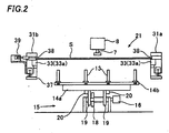
- Each of the head units 6a and 6b has a mounting head 8 mounted with a suction nozzle 7 (see Fig. 2 ) and a board recognition camera 50.
- a pair of component recognition cameras 10a and 10b is respectively provided on each side of the board supplying portion 3, and two nozzle stockers 11a and 11b are provided.
- the printed board S is supplied from a left side by the board supplying portion 3, fixed at a center of the base 2, and then discharged to a right side. Description will be given on a case where an electronic component supplied from the two tape cassette feeders 4a disposed in the front portion (lower side in Fig. 1 ) of the base 2 is mounted on the board S by using the first head unit 6a, for example.
- the first head unit 6a moves to the required tape cassette feeder 4a by operation of the X beam 5a, and the suction nozzle 7 picks a required electronic component up. Then, on the way to the board by operation of the Y beam 5b, the first head unit 6a moves the electronic component picked by the suction nozzle 7 to the component recognition camera 10a, and the component recognition camera 10a (in the front side of the base 2) recognizes a position of the electronic component. Furthermore, by operation of the Y beam 5b, the first head unit 6a moves to a predetermined position on the board S, the board recognition camera 50 mounted on the first head unit 6a recognizes a position of the board S, and mounts the electronic component on the board S.
- the board supplying portion 3 has a board positioning portion 21 provided at a center thereof, a board supplying conveyer portion 22 provided on a left side of the board positioning portion 21 in Fig. 1 and a board discharging conveyer portion 23 provided on a right side of the board positioning portion 21 in Fig. 1 .
- the board S is carried from outside of the device to the board positioning portion 21 by the board supplying conveyer portion 22, fixed on the board positioning portion 21 for being mounted with an electronic component, and supported from a lower side in order to avoid warping when the electronic component is mounted. Then, the board S finished with component mounting is discharged from the board positioning portion 21 to outside through the board discharging conveyer portion 23.
- the board S is supported by backup pins 13 described below (see Fig. 2 ) from a backside of the board S so as to avoid its warping.
- the positioning of the board S for component mounting differs depending on size, thickness, or whether or not components are previously attached to the backside of the board S. Therefore, many backup pins 13 repeat up and down movement when the board S is changed to boards of other types, in order to change those positionings properly for the new board S.
- the board positioning portion 21 has a fixed-side board carrying table 31a and a movable-side board carrying table 31b each supporting front, rear, left, and right portions of the board S, a carrying table moving device (not shown) moving the movable-side board carrying table 31b in front and rear directions corresponding to a width of the board S, and a board carrying device 33 of conveyer type (including conveyer rollers 33a and 33b, and a belt 34 described below) carrying the board S received from the board supplying conveyer portion 22 to predetermined component mounting positions of both the board carrying tables 31a and 31b by a belt and carrying the board S finished with component mounting from the component mounting position to the board discharging conveyer portion 23 by a belt.
- a numeral 39 designates an air cylinder, which positions the board S to the board supplying portion 3 in a width direction.
- a vertical shifting lever 37 shifts upward and downward through a presser (e.g. a spring 36) by activation of the air cylinder 39 fixed to the board carrying tables 31a and 31b so that the board S can be attached to and detached from a carrying level of the belt 34. That is, as shown in Fig. 3A , when the vertical shifting lever 37 is shifted to a lower side, the board S is positioned at the carrying level of the belt 34, thereby being carried to a downstream driven by the belt 34. When the vertical shifting lever 37 is shifted to an upper side as shown in Fig. 3B , the board S is positioned above the carrying level, thereby being released from a carrying operation of the belt 34.
- a presser e.g. a spring 36
- the board positioning portion 21 has many backup pins 13 supporting the board S set on the positioning position from a lower side, a backup table 14a set with the many backup pins 13 standing thereon, and a backup pin vertically shifting device 15 (see Figs. 2 and 5 ) shifting the backup pins 13 upward and downward through the backup table 14a.
- the fixed-side board carrying table 31a and the movable-side board carrying table 31b are disposed facing each other, and the backup table 14a and the backup pin vertical shifting device 15 are disposed below a space between the board carrying tables 31a and 31b.
- the backup table 14a is formed in a rectangle shape in plan view.
- a pin setting plate 14b for standing the backup pins 13 is placed on the backup table 14a, and formed with many setting holes for standing the backup pins 13.
- the backup table 14a shifts upward and downward by a following manner.
- the drive motor 16 is driven to rotate itself to make a cam 18 rotate through a belt 17, and a linking body 19 being in contact with the cam 18 rotates along an outer circumference of the cam 18. This rotation of the linking body 19 shifts the backup table 14a upward and downward, being pushed up by the tip portion 20 of the linking body 19.
- the fixed-side board carrying table 31a is formed with a guide groove 38 having a U-shape in cross-sectional view for guiding a side end portion of the board S, the guide groove 38 being formed of an inner portion of the fixed-side board carrying table 31a and a conveyer roller 33a of the board carrying device 33 attached to the inner portion.
- the movable-side board carrying table 31b is formed with a guide groove 38 having a U-shape in cross-sectional view for guiding a side end portion of the board S, the guide groove 38 being formed of an inner portion of the movable-side board carrying table 31b and a conveyer roller 33a of the board carrying device 33 attached to the inner portion.
- the movable-side board carrying table 31b is set with the air cylinder 39 at the guide groove 38, thereby enabling the board S to be pushed and fixed between the fixed-side board carrying table 31a and the movable-side board carrying table 31b.
- a first board detection sensor 40 and a second board detection sensor 41 each serving as a photo sensor for detecting the printed board S are provided in the board positioning portion 21, shown in Fig. 5 .
- a numeral 60 designates a CPU serving as a control device for controlling component picking and mounting operations of the mounter 1.
- a numeral 61 designates an RAM (random access memory) serving as a memory device, and a numeral 62 designates an ROM (read only memory).
- the CPU 60 controls each of drive sources for the component picking and mounting operations of the mounter 1 through an interface 64 and a drive circuit 65 based on data stored in the RAM 61 and according to programs stored in the ROM 62.
- the RAM 61 is stored with mounting data including X and Y coordinates and a mounting angle for each of step numbers (in mounting order) and component alignment numbers in the tape cassette feeder 4a, and component data including X and Y sizes for each of the electronic components and numbers of the suction nozzles 7 for use.
- a numeral 65 designates an operating portion, having a ten key 66 for keying numbers in, a cursor key 67, a set key 68 for setting mode and so on, an informing key 69 for setting the electronic component mounting device in informing mode, an automation key 70 for setting the electronic component mounting device in automation mode, a manually running key 71 for setting the electronic component mounting device in manually running mode, a start key 72, an activation key 73, and a stop key 74.
- a numeral 75 designates a recognition processing device connected with the CPU 60 through the interface 64.
- the recognition processing device 75 performs recognition processing to images taken and stored by each of the component recognition cameras 10a and 10b, and sends a recognition result to the CPU 60. That is, the CPU 60 outputs a command of performing recognition processing (e.g. calculation of a shifting amount of an electronic component from a normal position) to images taken and stored by each of the component recognition cameras 10a and 10b to the recognition processing device 75, and receives a recognition processing result from the recognition processing device 75.
- recognition processing e.g. calculation of a shifting amount of an electronic component from a normal position
- the recognition processing device 75 performs recognition processing and detects a shifting amount from a normal position
- this recognition result is sent to the CPU 60.
- the CPU 60 moves the first head unit 6a and the second head unit 6b in X and Y directions by driving the X axis motor 76 of the X beam 5a and the Y axis motor 77 of the Y beam 5b, and rotates the suction nozzle 7 by an angleè by driving a pulse motor 78, thereby completing correction of the position of the electronic component in the X and Y directions and the rotating angle along a vertical axis.
- the images taken by each of the component recognition cameras 10a and 10b are stored in the recognition processing device 75, and the stored images are displayed on the CRT 79.
- the CRT 79 is provided with various touch panel switches 80 and an operator operates the touch panel switches 80 for various settings including settings for informing.
- the touch panel switches 80 include a glass substrate which is coated with a transparent conductive film on its whole surface and printed with electrodes on its four edges.
- Numerals 81, 82, and 83 are servo motors for driving conveyers of the board supplying conveyer portion 22, the board positioning portion 21, and the board discharging conveyer portion 23 respectively, and operation of each of the servo motors 81, 82, and 83 makes the printed board S on each of the conveyers carried by a belt.
- these servo motors 81, 82, and 83 are motors which can control each position of the conveyers respectively but can be substituted by a pulse motor, for example.
- Basic data on operations of the servo motors 81, 82, and 83 are stored in the ROM 62 for disabling rewriting.
- the basic data can be stored in the RAM 61 in order to enable rewriting according to a request by a user.
- a data rewritable region (set arbitrarily) according to a request by a user can be provided in the RAM 61.
- these basic data are data on drive waveform of the motors, including automatic start data A, maximum speed data, acceleration/deceleration (incline) data, and carrying distance data of the motors, for example.
- a carrying time for one carriage can be specified by these data.
- a teaching running is an operation of the mounter to calibrate system and operational deviations.
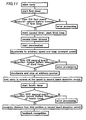
- the CPU 60 outputs a drive signal to the servo motors 81 and 82 of the board supplying conveyer portion 22 and the board positioning portion 21 through the interface 64 and the drive circuit 65 based on operation signals from the informing key 69 and the start key 72, thereby starting the carrying of the printed board S.
- a first timer 85 starts timekeeping at the same time as the start of the carrying of the board S.
- the CPU 60 controls the CRT 79 and other display devices and alarming devices to display an error.
- the second and third timers 86 and 87 start timekeeping.
- the CPU 60 controls the servo motors 81 and 82 through the interface 64 and the drive circuit 65 in order to start deceleration of the printed board S, decelerate the printed board S to an arbitrary speed, and keep the printed board S at a constant speed.
- the CPU 60 controls the CRT 79 and other display devices and alarming devices to display an error.
- the CPU 60 controls the servo motors 81 and 82 to decelerate the printed board S and then stop the printed board S at an arbitrary position ( Fig. 7 ).
- the board recognition camera 50 takes an image of a positioning mark 51 provided on the printed board S stopping at an arbitrary position of the board positioning portion 21, and the recognition processing device 75 performs recognition processing of the image to recognize a position of the printed board S.
- a result of the recognition is stored in the RAM 61, that is, a plus error is stored in the RAM 61 when a recognized position is on a more forward position than a predetermined set position and a minus error is stored in the RAM 61 when a recognized position is on a more backward position than the set position. This error is adjusted by combining with the carrying distance data stored in the RAM 61 in actual manufacturing running of the printed board S.
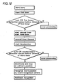
- the first timer 85 starts timekeeping at the same time as the start of the carrying of the board S.
- the CPU 60 controls the CRT 79 and other display devices and alarming devices to display an error.
- the second and third timers 86 and 87 start timekeeping.
- the CPU 60 controls the servo motors 81 and 82 through the interface 64 and the drive circuit 65 in order to start deceleration of the printed board S, decelerate the printed board S to an arbitrary speed, and keep the printed board S at a constant speed.
- the CPU 60 controls the CRT 79 and other display devices and alarming devices to display an error.
- the CPU 60 controls the servo motors 81 and 82 to decelerate the printed board S and then stop the printed board S at an arbitrary position.
- the CPU 60 reads out a recognition result of the recognition processing device 75 obtained in the teaching running described above from the RAM 61, and the manufacturing running is performed with feedback based on the recognition result (a plus error or a minus error).
- the CPU 60 adjusts a stopping position based on the position detected by encoders of the servo motors 81 and 82 (stop the printed board S at a more backward position by an error amount in a case of a plus error or at a more forward position by an error amount in a case of a minus error) so that the printed board S can decelerate toward an arbitrary position and stop there. That is, error adjustment is performed by using both the error and the carrying distance data stored in the RAM 61.
- the CPU 60 controls the servo motor 82 to reversely rotate and start the carrying of the printed board S in a reverse direction. This carrying is continued at low speed until the printed board S becomes undetectable by the second board detection sensor 41. At this time, the CPU 60 starts timekeeping of a fourth timer 88 at the same time as sending a command of driving reversely to the servo motors 81.
- the CPU 60 controls the CRT 79 and other display devices and alarming devices to display an error.
- the CPU 60 When the printed board S becomes undetectable by the second board detection sensor 41 before the timeout of the fourth timer 88, the CPU 60 reads out a content of the encoder of the servo motor 82 through the drive circuit 65, and calculates and recognizes the distance from a position where the printed board S stops to the second board detection sensor 41. Then, the CPU 60 stores a result of the recognition in the RAM 61, and uses the result for feedback in actual manufacturing running of the printed board S. That is; the CPU 60 controls the printed board S to stop at a more backward position by an amount of the distance from the position where the printed board S stops to the second board detection sensor 41.
- the CPU 60 reads out the recognition result obtained by the teaching running described above from the RAM 61.
- the CPU 60 controls the servo motors 81 and 82 to decelerate the printed board S and then stop the printed board S at an arbitrary position which is a position backwardly shifted by an amount of the distance from the position where the printed board S stops to the second board detection sensor 41 based on the recognition result.
- a first timer 85 starts timekeeping at the same time as the start of the carrying of the board S.
- the CPU 60 controls the CRT 79 and other display devices and alarming devices to display an error.
- the second and third timers 86 and 87 start timekeeping.
- the CPU 60 controls the servo motors 81 and 82 through the interface 64 and the drive circuit 65 in order to start deceleration of the printed board S. Then, when the second board detection sensor 41 does not detect the printed board S before timeout of the third timer 87 because the printed board S is caught and stops somewhere, the CPU 60 controls the CRT 79 and other display devices and alarming devices to display an error. When the second board detection sensor 41 detects the printed board S before the timeout of the third timer 87, the CPU 60 controls the servo motors 81 and 82 to decelerate the printed board S and then stop the printed board S at an arbitrary position.
- the board recognition camera 50 takes an image of a positioning mark 51 provided on the printed board S stopping at the arbitrary position of the board positioning portion 21, and the board processing device 75 performs recognition processing of the image to recognize a position of the printed board S.
- a result of the recognition is stored in the RAM 61, that is, a plus error is stored in the RAM 61 when a recognized position is on a more forward position than a set position and a minus error is stored in the RAM 61 when a recognized position is on a more backward position than the set position. This error is adjusted by combining with the carrying distance data stored in the RAM 61 in an actual manufacturing running of the printed board S.
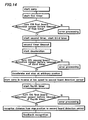
- the first timer 85 starts timekeeping at the same time as the start of the carrying of the board S.
- the CPU 60 controls the CRT 79 and other display devices and alarming devices to display an error.
- the second and third timers 86 and 87 start timekeeping.
- the CPU 60 controls the servo motors 81 and 82 through the interface 64 and the drive circuit 65 in order to start deceleration of the printed board S. Then, when the second board detection sensor 41 does not detect the printed board S before timeout of the third timer 87 because the printed board S is caught and stops somewhere, the CPU 60 controls the CRT 79 and other display devices and alarming devices to display an error. When the second board detection sensor 41 detects the printed board S before the timeout of the third timer 87, the CPU 60 controls the servo motors 81 and 82 to decelerate the printed board S and then stop the printed board S at an arbitrary position.
- the CPU 60 reads out the recognition result of the recognition processing device 75 obtained by the teaching running described above from the RAM 61, and the manufacturing running is performed with feedback based on the recognition result (a plus error or a minus error).
- the CPU 60 adjusts a stopping position based on the position detected by the encoders of the servo motors 81 and 82 (stop the printed board S at a more backward position by an error amount in a case of a plus error or at a position at a more forward position by an error amount in a case of a minus error), so that the printed board S can decelerate toward an arbitrary position and stop there. That is, error adjustment is performed by using both the error and the carrying distance data stored in the RAM 61.
- the CPU 60 controls the servo motor 82 to reversely rotate and start the carrying of the printed board S in a reverse direction. This carrying is continued at low speed until the printed board S becomes undetectable by the second board detection sensor 41. At this time, the CPU 60 starts timekeeping of a fourth timer 88 at the same time as sending a command of driving reversely to the servo motors 82.
- the CPU 60 controls the CRT 79 and other display devices and alarming devices to display an error.
- the CPU 60 When the printed board S becomes undetectable by the second board detection sensor 41 before the timeout of the fourth timer 88, the CPU 60 reads out a content of the encoder of the servo motor 82 through the drive circuit 65, and calculates and recognizes a distance from a position where the printed board S stops to the second board detection sensor 41. Then, the CPU 60 stores a result of the recognition in the RAM 61, and uses the result for feedback in actual manufacturing running of the printed board S. That is, the CPU 60 controls the printed board S to stop at a more backward position by an amount of the distance from the position where the printed board S stops to the second board detection sensor 41.
- the CPU 60 reads out the recognition result obtained by the teaching running described above from the RAM 61.
- the CPU 60 controls the servo motors 81 and 82 to decelerate the printed board S and then stop the printed board S at an arbitrary position which is a position backwardly shifted by an amount of the distance from the position where the printed board S stops to the second board detection sensor 41 based on the recognition result.
- the printed board S is carried from the board supplying conveyer portion 22 to the board positioning portion 21, and stops at a predetermined position of the board positioning portion 21.
- the air cylinder 39 is activated to fix the printed board S immovably in a width direction and upwardly shift the printed boards by upwardly shifting the vertical shifting lever 37 ( Fig. 3B ).
- the backup pin vertically shifting device 15 is activated to upwardly shift the printed board S to a mounting position and keep it horizontal there. Then, a component mounting operation by the mounting head 8 is performed at this position.
- a carrying operation of the printed board S finished with the component mounting operation starts.
- the air cylinder 39 is activated to downwardly shift the printed board S positioned at a mounting operation level to a carrying level of the conveyer.
- the printed board S is carried to the side of the board discharging conveyer portion 23 by conveyer driving of the board positioning portion 21 and the board discharging conveyer portion 23. After this, the board carrying operation and the component mounting operation will be repeated similarly.
- the invention is not limited to the embodiments and can be applied to devices of various types having a board carrying system.
Landscapes
- Engineering & Computer Science (AREA)
- Manufacturing & Machinery (AREA)
- Microelectronics & Electronic Packaging (AREA)
- Operations Research (AREA)
- Supply And Installment Of Electrical Components (AREA)
Claims (12)
- Plattenpositioniervorrichtung zum Positionieren einer Leiterplatte (S), aufweisend:- einen Plattenbeschickungsförderabschnitt (22);- einen Plattenpositionierabschnitt (21) zum Aufnehmen der Leiterplatte (S) vom Plattenbeschickungsförderabschnitt (22) und Positionieren der Leiterplatte (S) darin;- einen ersten Motor (81) zum Antreiben des Plattenbeschickungsförderabschnitts (22);- einen zweiten Motor (82) zum Antreiben des Plattenpositionierabschnitts (21);- einen ersten Plattenerfassungssensor (40) und einen zweiten Plattenerfassungssensor (41), der an einer weiter abwärts liegenden Position als der erste Plattenerfassungssensor (40) in Beförderungsrichtung der Leiterplatte (S) angeordnet ist;- einen ersten Zeitgeber (85), der zum Starten ausgebildet ist, wenn der Plattenbeschickungsförderabschnitt (22) mit der Beförderung der Leiterplatte (S) beginnt;dadurch gekennzeichnet, dass die Plattenpositioniervorrichtung des Weiteren Folgendes aufweist:- einen zweiten Zeitgeber (86) und einen dritten Zeitgeber (87), die zum Starten ausgebildet sind, wenn der erste Plattenerfassungssensor (40) die Leiterplatte (S) vor einer Zeitabschaltung des ersten Zeitgebers (85) erfasst;- eine Steuerung (60), die zum Steuern des ersten und zweiten Motors (81, 82) ausgebildet ist, so dass die Leiterplatte (S) sich zu bewegen beginnt, nach einer Zeitabschaltung des zweiten Zeitgebers (86) verlangsamt und an einer beliebigen Position im Plattenpositionierabschnitt (21) stoppt, wenn der zweite Plattenerfassungssensor (41) die Leiterplatte (S) vor einer Zeitabschaltung des dritten Zeitgebers (87) erfasst;- eine Plattenerkennungskamera (50), die zum Aufnehmen eines Bildes einer Positionierungsmarke (51) ausgebildet ist, die auf der Leiterplatte (S) vorgesehen ist, die an der beliebigen Position stoppt; und- eine Erkennungsverarbeitungsvorrichtung (75), die zum Erkennen einer Position der Leiterplatte (S) auf der Basis des Bildes, das von der Plattenerkennungskamera (50) aufgenommen wurde, ausgebildet ist, wobei die Steuerung (60) zum Steuern des ersten und zweiten Motors (81, 82) auf der Basis der erkannten Position ausgebildet ist.
- Plattenpositioniervorrichtung nach Anspruch 1, wobei die Steuerung zum derartigen Steuern des zweiten Motors (82) ausgebildet ist, dass die Leiterplatte (S) auf eine beliebige Geschwindigkeit verlangsamt wird und diese beibehält.
- Plattenpositioniervorrichtung nach Anspruch 1, wobei die Steuerung (60) zum Steuern des ersten und zweiten Motors (81, 82) auf der Basis des Ergebnisses der Erkennung durch die Erkennungsverarbeitungsvorrichtung (75) ausgebildet ist, wenn die Leiterplatte (S) zur Montage elektronischer Komponenten positioniert ist.
- Plattenpositioniervorrichtung zum Positionieren einer Leiterplatte, aufweisend:- einen Plattenbeschickungsförderabschnitt (22);- einen Plattenpositionierabschnitt (21) zum Aufnehmen der Leiterplatte (S) vom Plattenbeschickungsförderabschnitt (22) und Positionieren der Leiterplatte (S) darin;- einen ersten Motor (81) zum Antreiben des Plattenbeschickungsförderabschnitts (22);- einen zweiten Motor (82) zum Antreiben des Plattenpositionierabschnitts (21);- einen ersten Plattenerfassungssensor (40) und einen zweiten Plattenerfassungssensor (41), der an einer weiter abwärts liegenden Position als der erste Plattenerfassungssensor (40) in Beförderungsrichtung der Leiterplatte (S) angeordnet ist;- einen ersten Zeitgeber (85), der zum Starten ausgebildet ist, wenn der Plattenbeschickungsförderabschnitt (22) mit der Beförderung der Leiterplatte (S) beginnt;dadurch gekennzeichnet, dass die Plattenpositioniervorrichtung des Weiteren Folgendes aufweist:- einen zweiten Zeitgeber (86) und einen dritten Zeitgeber (87), die zum Starten ausgebildet sind, wenn der erste Plattenerfassungssensor (40) die Leiterplatte (S) vor einer Zeitabschaltung des ersten Zeitgebers (85) erfasst;- eine Steuerung (60), die zum Steuern des ersten und zweiten Motors (81, 82) ausgebildet ist, so dass die Leiterplatte (S) sich zu bewegen beginnt, nach einer Zeitabschaltung des zweiten Zeitgebers (86) verlangsamt und an einer beliebigen Position im Plattenpositionierabschnitt (21) stoppt, wenn der zweite Plattenerfassungssensor (41) die Leiterplatte (S) vor einer Zeitabschaltung des dritten Zeitgebers (87) erfasst;- einen vierten Zeitgeber (88); und- eine Erkennungsvorrichtung, wobei die Steuerung (60) zum derartigen Steuern des ersten und zweiten Motors (81, 82) ausgebildet ist, dass sich die Leiterplatte (S) aus einer beliebigen Position in eine umgekehrte Richtung bewegt, bis der zweite Plattenerfassungssensor (41) das Erfassen der Leiterplatte (S) stoppt, und dass der vierte Zeitgeber (88) zum Starten mit dem Beginn der umgekehrten Bewegung ausgebildet ist, die Erkennungsvorrichtung zum Berechnen eines Abstandes zwischen der beliebigen Position und dem zweiten Plattenerfassungssensor (41) auf der Basis einer Ablesung einer Codiervorrichtung des zweiten Motors (82) entsprechend dem Stoppen der Erfassung der Leiterplatte (S) vor einer Zeitabschaltung des vierten Zeitgebers (88) ausgebildet ist und die Steuerung zum Steuern des ersten und zweiten Motors (81, 82) auf der Basis des berechneten Abstandes ausgebildet ist.
- Plattenpositioniervorrichtung nach Anspruch 4, wobei die Steuerung (60) zum derartigen Steuern des zweiten Motors (82) ausgebildet ist, dass die Leiterplatte (S) auf eine beliebige Geschwindigkeit verlangsamt wird und diese beibehält.
- Plattenpositioniervorrichtung nach Anspruch 4, wobei die Steuerung (60) zum Steuern des ersten und zweiten Motors (81, 82) auf der Basis des berechneten Abstandes ausgebildet ist, wenn die Leiterplatte (S) zur Montage elektronischer Komponenten positioniert ist.
- Verfahren zum Positionieren einer Leiterplatte, aufweisend:- Starten der Beförderung der Leiterplatte (S) zu einer Positionierungsstelle;- Starten eines ersten Zeitgebers (85), wenn die Beförderung der Leiterplatte (S) beginnt;- Starten eines zweiten Zeitgebers (86) und eines dritten Zeitgebers (87), wenn ein erster Plattenerfassungssensor (40) die Leiterplatte (S), die zur Positionierungsstelle befördert wird, vor einer Zeitabschaltung des ersten Zeitgebers (85) erfasst;- Starten der Verlangsamung der beförderten Leiterplatte nach einer Zeitabschaltung des zweiten Zeitgebers (86);- Stoppen der Leiterplatte (S) an einer beliebigen Position, wenn ein zweiter Plattenerfassungssensor (41) die Leiterplatte (S) vor einer Zeitabschaltung des dritten Zeitgebers (87) erfasst;- Aufnehmen eines Bildes einer Positionierungsmarke (51), die auf der Leiterplatte (S) vorgesehen ist, die an der beliebigen Position stoppt, mit Hilfe einer Plattenerkennungskamera (50);- Erkennen einer Position der Leiterplatte (S) auf der Basis des Bildes, das von der Plattenerkennungskamera (50) aufgenommen wurde; und- Befördern einer anderen Leiterplatte zu der Positionierungsstelle auf der Basis der erkannten Position der Leiterplatte (S).
- Verfahren nach Anspruch 7, des Weiteren aufweisend das Verlangsamen der Leiterplatte (S) auf eine beliebige Geschwindigkeit und Halten der Leiterplatte bei der beliebigen Geschwindigkeit nach der Zeitabschaltung des zweiten Zeitgebers (86).
- Verfahren nach Anspruch 7 oder 8, wobei die andere Leiterplatte zur Montage elektronischer Komponenten positioniert ist.
- Verfahren zum Positionieren einer Leiterplatte, aufweisend:- Starten der Beförderung der Leiterplatte (S) zu einer Positionierungsstelle;- Starten eines ersten Zeitgebers (85), wenn die Beförderung der Leiterplatte beginnt;- Starten eines zweiten Zeitgebers (86) und eines dritten Zeitgebers (87), wenn ein erster Plattenerfassungssensor (40) die Leiterplatte (S), die zur Positionierungsstelle befördert wird, vor einer Zeitabschaltung des ersten Zeitgebers (85) erfasst;- Starten der Verlangsamung der beförderten Leiterplatte (S) nach einer Zeitabschaltung des zweiten Zeitgebers (86);- Stoppen der Leiterplatte (S) an einer beliebigen Position, wenn ein zweiter Plattenerfassungssensor (41) die Leiterplatte (S) vor einer Zeitabschaltung des dritten Zeitgebers (87) erfasst;- Bewegen der Leiterplatte (S) aus der beliebigen Position in eine umgekehrte Richtung, bis der zweite Plattenerfassungssensor (41) das Erfassen der Leiterplatte (S) stoppt;- Starten eines vierten Zeitgebers (88), wenn die umgekehrte Bewegung beginnt;- Berechnen eines Abstandes zwischen der beliebigen Position und dem zweiten Plattenerfassungssensor (41) vor einer Zeitabschaltung des vierten Zeitgebers (88); und- Befördern einer anderen Leiterplatte zu der Positionierungsstelle auf der Basis des berechneten Abstandes.
- Verfahren nach Anspruch 10, des Weiteren aufweisend das Verlangsamen der Leiterplatte (S) auf eine beliebige Geschwindigkeit und Halten der Leiterplatte (S) bei der beliebigen Geschwindigkeit nach der Zeitabschaltung des zweiten Zeitgebers (86).
- Verfahren nach Anspruch 10 oder 11, wobei die andere Leiterplatte (S) zur Montage elektronischer Komponenten positioniert ist.
Applications Claiming Priority (2)
| Application Number | Priority Date | Filing Date | Title |
|---|---|---|---|
| JP2003297578 | 2003-08-21 | ||
| JP2003297578A JP4503954B2 (ja) | 2003-08-21 | 2003-08-21 | 基板位置決め装置及び基板位置決め方法 |
Publications (3)
| Publication Number | Publication Date |
|---|---|
| EP1509075A2 EP1509075A2 (de) | 2005-02-23 |
| EP1509075A3 EP1509075A3 (de) | 2007-08-29 |
| EP1509075B1 true EP1509075B1 (de) | 2013-10-09 |
Family
ID=34056248
Family Applications (1)
| Application Number | Title | Priority Date | Filing Date |
|---|---|---|---|
| EP04019989.5A Expired - Lifetime EP1509075B1 (de) | 2003-08-21 | 2004-08-23 | Vorrichtung und Verfahren zum Positionieren von Leiterplatten |
Country Status (4)
| Country | Link |
|---|---|
| US (1) | US7376486B2 (de) |
| EP (1) | EP1509075B1 (de) |
| JP (1) | JP4503954B2 (de) |
| KR (1) | KR101122356B1 (de) |
Families Citing this family (13)
| Publication number | Priority date | Publication date | Assignee | Title |
|---|---|---|---|---|
| WO2006090654A1 (en) * | 2005-02-25 | 2006-08-31 | Matsushita Electric Industrial Co., Ltd. | Mounter and board positioning method |
| JP4667152B2 (ja) * | 2005-03-25 | 2011-04-06 | 株式会社日立ハイテクインスツルメンツ | プリント基板組立装置及びプリント基板組立方法 |
| EP2081034B1 (de) * | 2008-01-16 | 2014-03-12 | ISMECA Semiconductor Holding SA | Anordnung und Verfahren zur Verarbeitung elektronischer Bauteile |
| WO2013124970A1 (ja) * | 2012-02-21 | 2013-08-29 | 富士機械製造株式会社 | 基板搬送装置 |
| JP5912764B2 (ja) | 2012-03-29 | 2016-04-27 | 平田機工株式会社 | 搬送ユニット及び搬送装置 |
| US8757357B2 (en) * | 2012-11-13 | 2014-06-24 | Shenzhen China Star Optoelectronics Technology Co., Ltd | Aligning apparatus and method for glass substrate |
| US9051128B2 (en) * | 2012-11-21 | 2015-06-09 | Shenzhen China Star Optoelectronics Technology Co., Ltd | Transmission device and transmission method for glass substrate |
| TWM458663U (zh) * | 2013-03-28 | 2013-08-01 | Test Research Inc | 物件輸送裝置 |
| FR3025397B1 (fr) | 2014-08-28 | 2019-06-07 | Europlacer Industries | Machine de report de composants electronique sur cartes et electroniques avec capteurs le long du convoyeur |
| JP6602584B2 (ja) * | 2015-07-24 | 2019-11-06 | 株式会社Fuji | 部品実装機 |
| EP4210448B1 (de) * | 2017-03-23 | 2026-02-18 | Fuji Corporation | Montagesystem und anzeigesteuerungsvorrichtung |
| JP7266103B2 (ja) * | 2019-09-06 | 2023-04-27 | 株式会社Fuji | 部品実装機のバックアップピン自動配置システム |
| CN113601954A (zh) * | 2021-08-11 | 2021-11-05 | 刘华 | 一种多功能锡膏印刷机及其控制方法 |
Family Cites Families (16)
| Publication number | Priority date | Publication date | Assignee | Title |
|---|---|---|---|---|
| US6288561B1 (en) * | 1988-05-16 | 2001-09-11 | Elm Technology Corporation | Method and apparatus for probing, testing, burn-in, repairing and programming of integrated circuits in a closed environment using a single apparatus |
| JPH04365522A (ja) * | 1990-07-04 | 1992-12-17 | Sanyo Electric Co Ltd | 基板搬送装置 |
| EP0497129B1 (de) * | 1991-01-28 | 1995-07-26 | Siemens Aktiengesellschaft | Vorrichtung zum Bestücken von Leiterplatten |
| JP2878899B2 (ja) * | 1992-05-07 | 1999-04-05 | 三菱電機株式会社 | 薄板フレームの搬送及び位置決め方法、並びにその装置 |
| US5321624A (en) * | 1992-10-06 | 1994-06-14 | Bell & Howell Phillipsburg Company | Insertion machine having multiple document detector |
| JPH1070398A (ja) | 1996-08-27 | 1998-03-10 | Toshiba Corp | 部品実装装置 |
| US6073342A (en) * | 1996-11-27 | 2000-06-13 | Fuji Machine Mfg., Co., Ltd. | Circuit-substrate-related-operation performing system |
| US6082724A (en) * | 1997-08-01 | 2000-07-04 | Heidelberger Druckmaschinen Ag | Variable speed signature collating apparatus |
| NL1007637C2 (nl) * | 1997-11-27 | 1999-05-31 | Hadewe Bv | Drukken en afwerken van documenten. |
| JP4046391B2 (ja) * | 1997-11-28 | 2008-02-13 | 松下電器産業株式会社 | プリント基板の搬送装置および搬送方法 |
| JP4523217B2 (ja) * | 1999-05-21 | 2010-08-11 | パナソニック株式会社 | 板状部材の搬送保持装置及びその方法、並びに部品実装装置 |
| JP2001044695A (ja) * | 1999-07-26 | 2001-02-16 | Fuji Mach Mfg Co Ltd | 基板搬送方法および基板コンベヤ |
| JP2003086995A (ja) * | 2001-09-17 | 2003-03-20 | Matsushita Electric Ind Co Ltd | 部品実装機への基板の搬入方法および装置 |
| JP2003101289A (ja) * | 2001-09-20 | 2003-04-04 | Matsushita Electric Ind Co Ltd | プリント基板の搬入方法および装置 |
| US7089066B2 (en) * | 2003-04-24 | 2006-08-08 | Colorado Vnet, Llc | Distributed control systems and methods |
| JP2005183679A (ja) * | 2003-12-19 | 2005-07-07 | Hitachi High-Tech Instruments Co Ltd | 電子部品装着システム及び電子部品装着方法 |
-
2003
- 2003-08-21 JP JP2003297578A patent/JP4503954B2/ja not_active Expired - Fee Related
-
2004
- 2004-08-18 US US10/920,449 patent/US7376486B2/en not_active Expired - Lifetime
- 2004-08-20 KR KR1020040065644A patent/KR101122356B1/ko not_active Expired - Fee Related
- 2004-08-23 EP EP04019989.5A patent/EP1509075B1/de not_active Expired - Lifetime
Also Published As
| Publication number | Publication date |
|---|---|
| EP1509075A2 (de) | 2005-02-23 |
| JP4503954B2 (ja) | 2010-07-14 |
| KR101122356B1 (ko) | 2012-06-13 |
| US7376486B2 (en) | 2008-05-20 |
| US20050080508A1 (en) | 2005-04-14 |
| JP2005072136A (ja) | 2005-03-17 |
| KR20050021239A (ko) | 2005-03-07 |
| EP1509075A3 (de) | 2007-08-29 |
Similar Documents
| Publication | Publication Date | Title |
|---|---|---|
| EP1509075B1 (de) | Vorrichtung und Verfahren zum Positionieren von Leiterplatten | |
| JP3086578B2 (ja) | 部品装着装置 | |
| KR101122864B1 (ko) | 전자 부품 장착 장치 | |
| JPH07193397A (ja) | 実装機の吸着ポイント補正装置 | |
| EP1686845B1 (de) | Verfahren und Vorrichtung zur Bestückung von elektronischen Bauelementen | |
| EP1771060B1 (de) | Einrichtung zur Montage von elektronischen Bauteilen | |
| EP1566994A2 (de) | Vorrichtung zur Montage von elektronischen Bauteilen | |
| EP1608212A2 (de) | Einrichtung und Verfahren zur Montage elektronischer Bauteile | |
| EP1781078B1 (de) | Elektronische Bauteile-Bestückungsvorrichtung | |
| JP2013201204A (ja) | 部品実装装置及び部品実装方法 | |
| JPH10335420A (ja) | ワークのアライメント装置 | |
| JP2001274594A (ja) | 基板搬送装置及び基板搬送方法 | |
| JP5203122B2 (ja) | 基板搬送装置 | |
| JP2006229095A (ja) | 基板位置決め装置及び基板位置決め方法 | |
| KR0148966B1 (ko) | 프린트 기판의 편차를 보상하는 칩마운트 시스템 및 그 제어방법 | |
| JP3133588B2 (ja) | 電子部品自動装着装置及び電子部品の装着方法 | |
| EP1814375B1 (de) | Vorrichtung zur Montage von elektronischen Bauteilen | |
| JP4559264B2 (ja) | 基板組立方法及び基板組立装置 | |
| JP2005243816A (ja) | 電子部品搭載装置 | |
| JP2511515B2 (ja) | 電子部品装着装置 | |
| JP2585914Y2 (ja) | 電子部品自動装着装置 | |
| JP3128409B2 (ja) | 電子部品自動装着装置及び電子部品の装着方法 | |
| JP2004071891A (ja) | 部品実装装置 | |
| JPH11220293A (ja) | 部品装着方法及び同装置 | |
| JP2005268313A (ja) | 電子部品装着装置 |
Legal Events
| Date | Code | Title | Description |
|---|---|---|---|
| PUAI | Public reference made under article 153(3) epc to a published international application that has entered the european phase |
Free format text: ORIGINAL CODE: 0009012 |
|
| AK | Designated contracting states |
Kind code of ref document: A2 Designated state(s): AT BE BG CH CY CZ DE DK EE ES FI FR GB GR HU IE IT LI LU MC NL PL PT RO SE SI SK TR |
|
| AX | Request for extension of the european patent |
Extension state: AL HR LT LV MK |
|
| PUAL | Search report despatched |
Free format text: ORIGINAL CODE: 0009013 |
|
| AK | Designated contracting states |
Kind code of ref document: A3 Designated state(s): AT BE BG CH CY CZ DE DK EE ES FI FR GB GR HU IE IT LI LU MC NL PL PT RO SE SI SK TR |
|
| AX | Request for extension of the european patent |
Extension state: AL HR LT LV MK |
|
| 17P | Request for examination filed |
Effective date: 20080229 |
|
| AKX | Designation fees paid |
Designated state(s): DE NL |
|
| 17Q | First examination report despatched |
Effective date: 20101025 |
|
| GRAP | Despatch of communication of intention to grant a patent |
Free format text: ORIGINAL CODE: EPIDOSNIGR1 |
|
| GRAS | Grant fee paid |
Free format text: ORIGINAL CODE: EPIDOSNIGR3 |
|
| GRAP | Despatch of communication of intention to grant a patent |
Free format text: ORIGINAL CODE: EPIDOSNIGR1 |
|
| INTG | Intention to grant announced |
Effective date: 20130423 |
|
| GRAA | (expected) grant |
Free format text: ORIGINAL CODE: 0009210 |
|
| AK | Designated contracting states |
Kind code of ref document: B1 Designated state(s): DE NL |
|
| REG | Reference to a national code |
Ref country code: DE Ref legal event code: R096 Ref document number: 602004043512 Country of ref document: DE Effective date: 20131205 |
|
| REG | Reference to a national code |
Ref country code: NL Ref legal event code: VDEP Effective date: 20131009 |
|
| PG25 | Lapsed in a contracting state [announced via postgrant information from national office to epo] |
Ref country code: NL Free format text: LAPSE BECAUSE OF FAILURE TO SUBMIT A TRANSLATION OF THE DESCRIPTION OR TO PAY THE FEE WITHIN THE PRESCRIBED TIME-LIMIT Effective date: 20131009 |
|
| REG | Reference to a national code |
Ref country code: DE Ref legal event code: R097 Ref document number: 602004043512 Country of ref document: DE |
|
| REG | Reference to a national code |
Ref country code: DE Ref legal event code: R082 Ref document number: 602004043512 Country of ref document: DE |
|
| PLBE | No opposition filed within time limit |
Free format text: ORIGINAL CODE: 0009261 |
|
| STAA | Information on the status of an ep patent application or granted ep patent |
Free format text: STATUS: NO OPPOSITION FILED WITHIN TIME LIMIT |
|
| 26N | No opposition filed |
Effective date: 20140710 |
|
| REG | Reference to a national code |
Ref country code: DE Ref legal event code: R097 Ref document number: 602004043512 Country of ref document: DE Effective date: 20140710 |
|
| REG | Reference to a national code |
Ref country code: DE Ref legal event code: R119 Ref document number: 602004043512 Country of ref document: DE |
|
| REG | Reference to a national code |
Ref country code: DE Ref legal event code: R119 Ref document number: 602004043512 Country of ref document: DE Effective date: 20150303 |
|
| PG25 | Lapsed in a contracting state [announced via postgrant information from national office to epo] |
Ref country code: DE Free format text: LAPSE BECAUSE OF NON-PAYMENT OF DUE FEES Effective date: 20150303 |