EP1508463B1 - Dachflügeltür - Google Patents
Dachflügeltür Download PDFInfo
- Publication number
- EP1508463B1 EP1508463B1 EP03102595A EP03102595A EP1508463B1 EP 1508463 B1 EP1508463 B1 EP 1508463B1 EP 03102595 A EP03102595 A EP 03102595A EP 03102595 A EP03102595 A EP 03102595A EP 1508463 B1 EP1508463 B1 EP 1508463B1
- Authority
- EP
- European Patent Office
- Prior art keywords
- roof
- roof wing
- door according
- hinge
- wing
- Prior art date
- Legal status (The legal status is an assumption and is not a legal conclusion. Google has not performed a legal analysis and makes no representation as to the accuracy of the status listed.)
- Expired - Lifetime
Links
- 238000010168 coupling process Methods 0.000 claims description 33
- 230000008878 coupling Effects 0.000 claims description 32
- 238000005859 coupling reaction Methods 0.000 claims description 32
- 238000010276 construction Methods 0.000 description 7
- 230000008901 benefit Effects 0.000 description 4
- 238000000926 separation method Methods 0.000 description 2
- 230000004308 accommodation Effects 0.000 description 1
- 238000009434 installation Methods 0.000 description 1
- 230000007257 malfunction Effects 0.000 description 1
Images


Classifications
-
- B—PERFORMING OPERATIONS; TRANSPORTING
- B60—VEHICLES IN GENERAL
- B60J—WINDOWS, WINDSCREENS, NON-FIXED ROOFS, DOORS, OR SIMILAR DEVICES FOR VEHICLES; REMOVABLE EXTERNAL PROTECTIVE COVERINGS SPECIALLY ADAPTED FOR VEHICLES
- B60J7/00—Non-fixed roofs; Roofs with movable panels, e.g. rotary sunroofs
- B60J7/08—Non-fixed roofs; Roofs with movable panels, e.g. rotary sunroofs of non-sliding type, i.e. movable or removable roofs or panels, e.g. let-down tops or roofs capable of being easily detached or of assuming a collapsed or inoperative position
- B60J7/16—Non-fixed roofs; Roofs with movable panels, e.g. rotary sunroofs of non-sliding type, i.e. movable or removable roofs or panels, e.g. let-down tops or roofs capable of being easily detached or of assuming a collapsed or inoperative position non-foldable and rigid, e.g. a one-piece hard-top or a single rigid roof panel
- B60J7/1628—Non-fixed roofs; Roofs with movable panels, e.g. rotary sunroofs of non-sliding type, i.e. movable or removable roofs or panels, e.g. let-down tops or roofs capable of being easily detached or of assuming a collapsed or inoperative position non-foldable and rigid, e.g. a one-piece hard-top or a single rigid roof panel for covering the passenger compartment
- B60J7/1635—Non-fixed roofs; Roofs with movable panels, e.g. rotary sunroofs of non-sliding type, i.e. movable or removable roofs or panels, e.g. let-down tops or roofs capable of being easily detached or of assuming a collapsed or inoperative position non-foldable and rigid, e.g. a one-piece hard-top or a single rigid roof panel for covering the passenger compartment of non-convertible vehicles
- B60J7/1657—Non-fixed roofs; Roofs with movable panels, e.g. rotary sunroofs of non-sliding type, i.e. movable or removable roofs or panels, e.g. let-down tops or roofs capable of being easily detached or of assuming a collapsed or inoperative position non-foldable and rigid, e.g. a one-piece hard-top or a single rigid roof panel for covering the passenger compartment of non-convertible vehicles at least a major part of the roof pivoting about a stationary axis
-
- B—PERFORMING OPERATIONS; TRANSPORTING
- B60—VEHICLES IN GENERAL
- B60J—WINDOWS, WINDSCREENS, NON-FIXED ROOFS, DOORS, OR SIMILAR DEVICES FOR VEHICLES; REMOVABLE EXTERNAL PROTECTIVE COVERINGS SPECIALLY ADAPTED FOR VEHICLES
- B60J7/00—Non-fixed roofs; Roofs with movable panels, e.g. rotary sunroofs
- B60J7/185—Locking arrangements
- B60J7/19—Locking arrangements for rigid panels
-
- E—FIXED CONSTRUCTIONS
- E05—LOCKS; KEYS; WINDOW OR DOOR FITTINGS; SAFES
- E05D—HINGES OR SUSPENSION DEVICES FOR DOORS, WINDOWS OR WINGS
- E05D7/00—Hinges or pivots of special construction
- E05D7/12—Hinges or pivots of special construction to allow easy detachment of the hinge from the wing or the frame
- E05D7/121—Hinges or pivots of special construction to allow easy detachment of the hinge from the wing or the frame specially adapted for vehicles
-
- E—FIXED CONSTRUCTIONS
- E05—LOCKS; KEYS; WINDOW OR DOOR FITTINGS; SAFES
- E05F—DEVICES FOR MOVING WINGS INTO OPEN OR CLOSED POSITION; CHECKS FOR WINGS; WING FITTINGS NOT OTHERWISE PROVIDED FOR, CONCERNED WITH THE FUNCTIONING OF THE WING
- E05F15/00—Power-operated mechanisms for wings
- E05F15/60—Power-operated mechanisms for wings using electrical actuators
- E05F15/603—Power-operated mechanisms for wings using electrical actuators using rotary electromotors
- E05F15/611—Power-operated mechanisms for wings using electrical actuators using rotary electromotors for swinging wings
- E05F15/614—Power-operated mechanisms for wings using electrical actuators using rotary electromotors for swinging wings operated by meshing gear wheels, one of which being mounted at the wing pivot axis; operated by a motor acting directly on the wing pivot axis
-
- E—FIXED CONSTRUCTIONS
- E05—LOCKS; KEYS; WINDOW OR DOOR FITTINGS; SAFES
- E05D—HINGES OR SUSPENSION DEVICES FOR DOORS, WINDOWS OR WINGS
- E05D7/00—Hinges or pivots of special construction
- E05D7/12—Hinges or pivots of special construction to allow easy detachment of the hinge from the wing or the frame
- E05D2007/128—Hinges or pivots of special construction to allow easy detachment of the hinge from the wing or the frame in a radial direction
-
- E—FIXED CONSTRUCTIONS
- E05—LOCKS; KEYS; WINDOW OR DOOR FITTINGS; SAFES
- E05Y—INDEXING SCHEME ASSOCIATED WITH SUBCLASSES E05D AND E05F, RELATING TO CONSTRUCTION ELEMENTS, ELECTRIC CONTROL, POWER SUPPLY, POWER SIGNAL OR TRANSMISSION, USER INTERFACES, MOUNTING OR COUPLING, DETAILS, ACCESSORIES, AUXILIARY OPERATIONS NOT OTHERWISE PROVIDED FOR, APPLICATION THEREOF
- E05Y2201/00—Constructional elements; Accessories therefor
- E05Y2201/20—Brakes; Disengaging means; Holders; Stops; Valves; Accessories therefor
- E05Y2201/214—Disengaging means
-
- E—FIXED CONSTRUCTIONS
- E05—LOCKS; KEYS; WINDOW OR DOOR FITTINGS; SAFES
- E05Y—INDEXING SCHEME ASSOCIATED WITH SUBCLASSES E05D AND E05F, RELATING TO CONSTRUCTION ELEMENTS, ELECTRIC CONTROL, POWER SUPPLY, POWER SIGNAL OR TRANSMISSION, USER INTERFACES, MOUNTING OR COUPLING, DETAILS, ACCESSORIES, AUXILIARY OPERATIONS NOT OTHERWISE PROVIDED FOR, APPLICATION THEREOF
- E05Y2900/00—Application of doors, windows, wings or fittings thereof
- E05Y2900/50—Application of doors, windows, wings or fittings thereof for vehicles
- E05Y2900/53—Type of wing
- E05Y2900/546—Tailboards, tailgates or sideboards opening upwards
Definitions
- the invention relates to a roof wing door for a motor vehicle, comprising two door elements, namely a side door and an adjoining hinged roof spoiler, which is arranged in a vehicle roof, wherein at least one hinge is provided, via which the roof wing is mounted swingably on the vehicle roof.
- a generic roof wing door is from the US 2,857,198 known. It comprises a conventional side door with window frames and a roof wing, which can be swung around an axis arranged in the longitudinal direction of the vehicle from the roof surface of the vehicle.
- the roof door is open when both the side door is open and the roof wing is folded up.
- the known construction simplifies getting into and out of the vehicle, because the passenger does not have to bend in order to get past a roof edge on a vehicle seat. It is regarded as a disadvantage of the known elaborate roof wing door, that there is no additional benefit for the use of the motor vehicle except for the entry and exit.
- the invention has the object of developing a roof wing door so that there are more uses for a vehicle equipped with it, the roof wing door should always be easy to handle.
- the object is achieved in that a locking device is provided, with which the roof wing is detachably attached to the hinge.
- the body of a motor vehicle has become variable with the roof wing door according to the invention.
- the motor vehicle can optionally with closed body or operated with the body open.
- bodies of a motor vehicle are either closed or have the possibility of being partially opened, in that body parts can be folded, folded or removed.
- the roof wing door according to the invention allows with locking device to remove the roof wing and to use the motor vehicle with the roof open; Depending on the size of the roof wing, the driving impression can come close to that of a convertible.
- a motor vehicle can be equipped both on the driver and on the passenger side with roof doors.
- a motor vehicle with such a door construction can be designed as a two-door or for example as a four-door motor vehicle.
- a hinge according to the invention are in addition to hinges which are rotatable about an axis, also coupling devices understood, via which a roof wing is swingable on a path that deviates from a circular path.
- the axis of a rotary hinge or lie the axes of a coupling device in the longitudinal direction of the motor vehicle.
- the locking device expediently has a hand lock provided directly on the roof wing for releasing and fixing the connection between the hinge and the roof wing. This makes the construction particularly easy.
- the operator can remove or attach the roof wing very quickly by pressing the manual closure. The latter allows a rapid closing of the vehicle roof, for example in the event of rain.
- the locking device instead of a manual closure on a switchable automatic closure for releasing and fixing the connection between the hinge and the roof wing.
- a manual Operation for removing or attaching the roof wing is omitted for the operator.
- the roof wing can be removed immediately from the vehicle roof.
- To fix the roof wing is simply inserted into a predetermined position in the vehicle roof and the automatic closure switched.
- a corresponding actuating element is arranged in the passenger compartment of the motor vehicle.
- a third embodiment has a locking device, which is provided with both a manual closure and with a switchable automatic closure for releasing and fixing the connection between the hinge and the roof wing.
- the roof wing can optionally be solved or fixed in one way or another.
- the handling is comfortable with the automatic closure. Usually, the roof wing is switched by automatic closure. Because of the manual closure handling is also safe, because in case of malfunction of the automatic closure, the function of the locking device is ensured by the hand lock.
- the automatic closure has a locking element and a drive device for the locking element, wherein the locking element and the drive device are released from each other in the open state of the roof wing.
- the separation between the locking element and drive device avoids that the masses of the parts of the drive device must be mitgeschwungen when opening the roof leaf.
- the design simplifies in this way and saves weight for the roof wing and drive power for a vibratory drive. The latter can also be dimensioned smaller and lighter.
- the locking element is arranged both in the mounted state and in the released state of the roof wing on the hinge and is swingable with this. By opening the roof wing, the locking element is released from the associated drive device, so that the roof wing without additional attachments can be raised.
- the locking element of the automatic closure can be actuated by a rotary movement.
- a lock By turning a lock is particularly space-saving possible.
- the locking element can perform a screwing movement, with the roof wing and hinge are braced against each other.
- the locking element may be designed in the manner of a bayonet closure, in which locking elements secure the connection between the roof wing and the hinge.
- the automatic closure has a coupling device, via which the locking element can be coupled to the drive device.
- the coupling device the separation between the locking element and the drive device is made.
- the coupling device expediently has two coupling parts which are movable toward and away from one another, wherein the coupling parts can be engaged with each other by a movement towards one another.
- a coupling part is designed as a rotary adapter and the second coupling part as a driving piece, wherein the rotary adapter is arranged stationary relative to the vehicle roof and the driving piece rotatably disposed on the locking element and is swingable with this.
- the locking device can be actuated to release the roof wing from the hinge or to fix it to the hinge. In the released state, the roof wing can then be pulled out of the roof surface to remove it. Conversely, the roof wing is simply slid into the roof surface to lock it to the hinge fix and close the roof surface.
- the handling is simplified by the fact that the rotary adapter and the driving piece are switched on and disengaged by opening and closing the roof wing, wherein the coupling device is engaged in the closed state of the roof wing and disengaged in the open state of the roof wing.
- the coupling device is engaged in the closed state of the roof wing and disengaged in the open state of the roof wing.
- For coupling and disengaging the construction makes use of the swinging motion of the roof wing, so that the coupling process is almost automatic.
- the rotary adapter and the driving piece of the coupling device cooperate in a form-fitting manner.
- To engage rotating adapter and driving piece are relative to each other in a matching rotational position to each other.
- the positive connection is made or eliminated by the swinging movement of the roof wing.
- the rotary adapter is provided with a rotary drive.
- the rotary actuator is part of the automatic closure and is switched via an actuator.
- the rotary drive has a traction mechanism.
- the traction means is connected to the rotary adapter and puts this in a forward or backward locking movement.
- the rotary adapter thus forms the output side of a traction mechanism.
- the drive side of the traction mechanism with drive motor is arranged at a suitable location in the vehicle roof, which has enough space for accommodation.
- roof spoiler doors are arranged on the driver and the passenger side of a motor vehicle, wherein between the roof spoils extending in the longitudinal direction of the vehicle roof bar of the vehicle roof remains. In the area of this roof bar are the required drive devices for the automatic closure arranged.
- the handling of the roof door can be further improved if a swing drive is provided for the roof wing.
- the swing drive is required for folding up and down the roof leaf. He is expediently also arranged in the roof bar of the vehicle roof.
- the oscillating drive is preferably arranged outside of the roof wing in the vehicle roof.
- the oscillating drive for the roof wing is designed as an electromechanical oscillating drive.
- the oscillating drive is coupled to the hinge.
- the benefit of a motor vehicle equipped with a roof wing door according to the invention can be further improved if the side door is designed as a frameless door. With the roof spoiler removed and the side window lowered, the result is an open feel similar to that of a convertible. Only the narrow roof bar curtails the openness of the body. There is freedom to the side as well as to the open roof.
- a further advantageous embodiment of the invention provides that the roof wing is automatically locked by means of the locking device on the hinge, after he is a predetermined time in the space provided.
- the intended installation position of the roof wing is detected in the hinge. Remains the roof wing relative to the hinge for a certain time in this position, the roof wing is automatically locked to the hinge by the locking device controlled by a suitable control device becomes.
- a preferred amount of time is when the wing is in this position for more than 1 second.
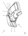
- a two-door motor vehicle 1 is shown schematically. Both on the driver and on the passenger side of the motor vehicle 1 is ever a roof door 2 is provided.
- the roof door 2 on the driver's side is shown in the open state. It comprises a side door 3 with a frameless side window 4 and a roof wing 5.
- the side door 3 is articulated in front of the vehicle body in the direction of travel.
- the roof wing 5 is about an approximately longitudinal direction of the motor vehicle. 1 lying axis folded up from the roof surface of the vehicle roof 7.
- the roof door of the passenger side has a mirror-image construction. It is shown closed.
- Each roof wing 5 is swingably attached to the vehicle roof 7 via two hinges 6a and 6b.
- a locking device is provided (not visible here) with which the roof wing 5 can be detached from the hinges 6a and 6b.
- the detached roof spoiler 5 is carried for example in the trunk of the vehicle.
- the roof wing 5 can be fixed again at any time to the hinges 6a and 6b. With removed roof wings 5 and lowered side windows 4 of the side doors 3, the occupants get freedom to the side and up and a similar driving experience as in a convertible.
- a roof ridge 8 is present, are arranged in the parts of the locking device and parts of a vibratory drive for the two roof spoiler 5.
- the roof spoiler 5 can be removed in the folded-down, closed state of the vehicle roof 7.
- the construction is designed so that a release of the locking device is possible only in the closed position of the roof spoiler 5. This is an advantage of the proposed roof door 2, because almost no components of the locking device when operating a roof leaf 5 with swinging up and down.
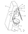
- Fig. 2 is the roof wing 5 according to Fig. 1 shown in detail. It is shown the back of the hinge 6a, with which the roof wing 5 is articulated to the vehicle roof 7. In the illustrated position of the hinge 6a of the roof wing 5 is folded down and the vehicle roof 7 is closed. The illustrated mechanical components are located in the region of the roof land 8 of the vehicle roof 7. A vibration drive 9 can be seen, with which the hinge 6a can be opened and closed. The hinge 6b may also be provided with a vibratory drive.
- the oscillating drive 9 essentially has a drive motor 10 with a drive pinion 11 on a motor shaft 12 of the drive motor 10 and an output pinion 13 on a drive shaft 14 for the hinge 6a.
- the output pinion 13 with a small diameter is rotatably received on a shaft end of the drive shaft 14.
- the hinge 6a is rotatably mounted at the opposite end of the drive shaft 14.
- the pinions 11 and 13 cause a translation into speed, since the drive pinion 11 on the motor shaft 12 has a larger diameter than the output pinion 13, which is arranged with the hinge 6a on a shaft.
- a locking device 15 is provided with an automatic closure.
- the locking device 15 or the automatic closure has a locking element 16.
- the locking element 16 is arranged in a receiving opening 17 of the roof wing 5.
- the locking element 16 To actuate the locking element 16, for example in order to release the connection between the roof wing 5 and hinge 6a, the locking element 16 must be rotated. A rotation of the locking member 16 is provided only in closed Ste I-ment of the roof wing 5. In this way, it is spared to have to install components of the locking device 15 in the roof spoiler 5, whose mass would always have to be moved during a swinging movement of the roof wing 5.
- a rotary drive with a pull strap 18 is shown in detail.
- the tension belt 18 is deflected on a coupling part, which is described below with reference to the Fig. 3 is explained in more detail.
- the coupling part is located directly in the vicinity of the hinge 6a, namely the locking element 16 opposite.
- the hinge 6a is thus located between the locking element 16 and the coupling part.
- Fig. 3 shows the roof wing 5 according to Fig. 2 from a different perspective and when folded up. In this perspective, the front of the hinge 6a can be seen. The locking element 16 in the roof wing 5 is not visible in this perspective.
- a coupling device 19 will be explained which Part of the locking device 15 and the automatic closure is.
- the coupling device 19 has two coupling parts, namely the above-mentioned coupling part with pull strap 18 and a second coupling part, which is firmly connected to the locking element 16 and according to Fig. 3 on the side facing away from the locking member 16 protrudes out of the hinge 6a out.
- the coupling part with pull strap 18 is designed as a rotary adapter 20 and arranged stationary relative to the vehicle roof 7.
- the provided on the hinge 6a coupling part is designed as a driving piece 21 on the locking member 16 and rotatably mounted in the hinge.
- the driving piece can be coupled by a closing the roof spoiler 5 swinging movement in the direction of the dashed arrow X in the rotary adapter 20.
- the engaged position is best viewed in the enlarged view Fig. 4 recognizable. Incidentally, also shows Fig. 2 the engaged position, wherein in Fig. 2 only the rotary adapter 20 is visible, but the coupled driving piece 21 is hidden.
- the driving piece 21 fits according to Fig. 4 in the folded-down state of the hinge 6a form fit into the rotary adapter 20 into it.
- the locking member 16 To release the roof wing 5 from the hinge 6a or fixing the roof wing 5 on the hinge 6a, the locking member 16 must be rotated.
- the rotational movement is introduced via the rotary drive with the pull belt 18, the rotary adapter 20 and the driving piece 21.
- the pull strap 18 is in the Figures 2 . 3, and 4 shown.
- a drive device with a large space requirement would hinder the headroom of the vehicle occupants. For this reason, the drive for the rotary adapter 20 is moved to a different location in the vehicle roof 7 and is transferred to the rotary adapter 20 with the help of the pull belt 18 to save space.
- the pull belt 18 For the purpose of actuation of the locking element 16, the pull belt 18 is set in motion and the rotary adapter 20 is rotated.
- the rotary adapter 20 rotates the driving piece 21 and thus the locking member 16 by the movement of the locking member 16 in a rotational direction of the roof wing 5 is released from the hinge 6a and by a movement of the locking member 16 in the opposite direction of rotation of the roof wing 5 on the hinge 6a fixed.
- FIG. 5 An alternative embodiment of a roof door is in Fig. 5 shown.
- the construction and the function correspond to the execution, which is based on the Figures 2 . 3 and 4 has been explained.
- the locking device 15 is provided in addition to the automatic closure with a hand closure 22.
- the automatic closure has a rotary drive with pull strap 18 for a rotary adapter 20.
- the rotary adapter 20 can optionally be actuated directly via the additional manual closure 22.
Landscapes
- Engineering & Computer Science (AREA)
- Mechanical Engineering (AREA)
- Power-Operated Mechanisms For Wings (AREA)
- Lock And Its Accessories (AREA)
Description
- Die Erfindung betrifft eine Dachflügeltür für ein Kraftfahrzeug, umfassend zwei Türelemente, nämlich eine Seitentür sowie einen daran angrenzenden aufschwingbaren Dachflügel, der in einem Fahrzeugdach angeordnet ist, wobei wenigstens ein Scharnier vorgesehen ist, über das der Dachflügel schwingbar an dem Fahrzeugdach angebracht ist.
- Eine gattungsgemäße Dachflügeltür ist aus der
US 2,857,198 bekannt. Sie umfasst eine konventionelle Seitentür mit Fensterrahmen sowie einen Dachflügel, der um eine in Längsrichtung des Fahrzeugs angeordnete Achse aus der Dachfläche des Fahrzeugs aufschwingbar ist. Die Dachflügeltür ist geöffnet, wenn sowohl die Seitentür geöffnet als auch der Dachflügel hochgeklappt ist. In dieser Stellung vereinfacht die bekannte Konstruktion das Ein- und Aussteigen in das Fahrzeug, weil sich der Fahrgast nicht beugen muss, um an einer Dachkante vorbei auf einen Fahrzeugsitz zu gelangen. Es wird als Nachteil der bekannten aufwendigen Dachflügeltür angesehen, dass sich außer für den Ein- und Ausstieg kein zusätzlicher Nutzen für die Verwendung des Kraftfahrzeugs ergibt. - Der Erfindung liegt die Aufgabe zugrunde, eine Dachflügeltür so weiterzubilden, dass sich für ein damit ausgerüstetes Kraftfahrzeug weitere Nutzungsmöglichkeiten ergeben, wobei die Dachflügeltür stets einfach handhabbar sein soll.
- Erfindungsgemäß wird die Aufgabe dadurch gelöst, dass eine Arretiervorrichtung vorgesehen ist, mit der der Dachflügel lösbar an dem Scharnier angebracht ist.
- Die Karosserie eines Kraftfahrzeugs ist mit der erfindungsgemäßen Dachflügeltür variabel geworden. Das Kraftfahrzeug kann wahlweise mit geschlossener Karosserie oder mit geöffneter Karosserie betrieben werden. Grundsätzlich sind Karosserien eines Kraftfahrzeugs entweder geschlossen oder besitzen die Möglichkeit bereichsweise geöffnet zu werden, indem Karosserieteile faltbar, klappbar oder entfernbar sind. Bei der oben erwähnten Karosserie gemäß der
US 2,857,198 handelt es sich um eine geschlossene Karosserie mit Dachflügeltüren, zur Variabilität der Karosserie leistet die bekannte Dachflügeltür keinerlei Beitrag. Demgegenüber gestattet die erfindungsgemäße Dachflügeltür mit Arretiervorrichtung, den Dachflügel zu entfernen und das Kraftfahrzeug mit geöffnetem Dach zu benutzen; je nach Größe des Dachflügels kann der Fahreindruck dem eines Kabrioletts nahe kommen. - An sich sind auch solche Dachflügeltüren bekannt, siehe z.B. die
US 2002/0079719 A1 oder dieJP 62-091316 - Selbstverständlich kann ein Kraftfahrzeug sowohl auf der Fahrer- als auch auf der Beifahrerseite mit Dachflügeltüren ausgestattet sein. Ein Kraftfahrzeug mit derartiger Türkonstruktion kann als zweitüriges oder beispielsweise auch als viertüriges Kraftfahrzeug ausgeführt sein.
- Als Scharnier im Sinne der Erfindung werden nebst Scharnieren, die um eine Achse drehbar sind, auch Koppelvorrichtungen verstanden, über die ein Dachflügel auf einer Bahn schwingbar ist, die von einer Kreisbahn abweicht. Bevorzugt liegt die Achse eines Drehscharniers beziehungsweise liegen die Achsen einer Koppelvorrichtung in Längsrichtung des Kraftfahrzeugs.
- Zweckmäßig weist die Arretiervorrichtung einen unmittelbar an dem Dachflügel vorgesehenen Handverschluss zum Lösen und Fixieren der Verbindung zwischen Scharnier und Dachflügel auf. Dadurch ist die Konstruktion besonders einfach. Der Bediener kann durch Betätigung des Handverschlusses den Dachflügel sehr schnell abnehmen oder anbringen. Letzteres gewährt ein rasches Schließen des Fahrzeugdachs, beispielsweise bei aufkommenden Regen.
- Bei einer weitere Ausführungsform der Dachflügeltür weist die Arretiervorrichtung anstelle eines Handverschlusses einen schaltbaren Automatikverschluss zum Lösen und Fixieren der Verbindung zwischen Scharnier und Dachflügel auf. Eine manuelle Betätigung zum Entfernen oder Anbringen des Dachflügels entfällt für den Bediener. Durch eine Schaltung des Automatikverschlusses zwecks Lösen der Verbindung kann der Dachflügel sofort aus dem Fahrzeugdach abgezogen werden. Zum Fixieren wird der Dachflügel einfach in eine vorgegebene Position im Fahrzeugdach eingelegt und der Automatikverschluss geschaltet. Um den Automatikverschluss zu aktivieren, ist im Fahrgastraum des Kraftfahrzeugs ein entsprechendes Betätigungselement angeordnet.
- Eine dritte Ausführungsform weist eine Arretiervorrichtung auf, die sowohl mit einem Handverschluss als auch mit einem schaltbaren Automatikverschluss zum Lösen und Fixieren der Verbindung zwischen Scharnier und Dachflügel versehen ist. Der Dachflügel kann wahlweise auf die eine oder andere Art gelöst beziehungsweise fixiert werden. Die Handhabung ist mit dem Automatikverschluss komfortabel. Üblicherweise wird der Dachflügel per Automatikverschluss geschaltet. Wegen des Handverschlusses ist die Handhabung darüber hinaus sicher, weil bei Betriebsstörungen des Automatikverschlusses die Funktion der Arretiervorrichtung durch den Handverschluss gewährleistet ist.
- Bevorzugt weist der Automatikverschluss ein Arretierelement sowie eine Antriebseinrichtung für das Arretierelement auf, wobei das Arretierelement und die Antriebseinrichtung im geöffneten Zustand des Dachflügels voneinander gelöst sind. Die Trennung zwischen Arretierelement und Antriebseinrichtung vermeidet, dass die Massen der Teile der Antriebseinrichtung beim Öffnen des Dachflügels mitgeschwungen werden müssen. Die Konstruktion vereinfacht sich auf diese Weise und spart Gewicht für den Dachflügel und Antriebsleistung für einen Schwingantrieb. Letzterer kann dadurch ebenfalls kleiner und leichter dimensioniert werden.
- Günstig ist es, wenn das Arretierelement sowohl im montierten Zustand als auch im gelösten Zustand des Dachflügels an dem Scharnier angeordnet und mit diesem schwingbar ist. Durch Öffnen des Dachflügels wird das Arretierelement von der zugeordneten Antriebseinrichtung gelöst, sodass der Dachflügel ohne weitere Anbauteile aufgeschwungen werden kann.
- Günstig ist das Arretierelement des Automatikverschlusses durch eine Drehbewegung betätigbar. Durch eine Drehung ist eine Arretierung besonders platzsparend möglich. Durch den drehenden Antrieb kann das Arretierelement eine Schraubbewegung durchführen, wobei Dachflügel und Scharnier gegeneinander verspannt werden. Alternativ kann das Arretierelement nach Art eines Bajonettverschlusses ausgebildet sein, bei dem Rastelemente die Verbindung zwischen Dachflügel und Scharnier sichern.
- Hilfreich ist es, wenn der Automatikverschluss eine Kupplungseinrichtung aufweist, über die das Arretierelement mit der Antriebseinrichtung kuppelbar ist. Über die Kupplungseinrichtung wird die Trennung zwischen Arretierelement und dessen Antriebseinrichtung vorgenommen.
- Zweckmäßig weist die Kupplungseinrichtung zwei Kupplungsteile auf, die aufeinander zu- und voneinander wegbewegbar sind, wobei die Kupplungsteile durch eine Bewegung aufeinander zu einkuppelbar sind. Vorteilhaft ist ein Kupplungsteil als Drehadapter und das zweite Kupplungsteil als Mitnahmestück ausgebildet ist, wobei der Drehadapter relativ zu dem Fahrzeugdach stationär angeordnet ist und das Mitnahmestück drehfest an dem Arretierelement angeordnet und mit diesem schwingbar ist.
- Durch ein Herabschwingen des Dachflügels aus einer hochgeklappten Position wird das mit dem Mitnahmestück versehene Arretierelement an dem Scharnier lagernd auf den stationär in dem Fahrzeugdach angeordneten Drehadapter geklappt und in diesem eingekuppelt. Nur in dieser geschlossenen Position des Dachflügels kann die Arretiervorrichtung betätigt werden, um den Dachflügel von dem Scharnier zu lösen oder an dem Scharnier zu fixieren. Im gelösten Zustand kann der Dachflügel dann aus der Dachfläche herausgezogen werden, um ihn zu entfernen. Umgekehrt wird der Dachflügel einfach in die Dachfläche eingeschoben, um ihn an dem Scharnier zu fixieren und die Dachfläche zu schließen.
- Vereinfacht wird die Handhabung dadurch, dass der Drehadapter und das Mitnahmestück durch Öffnen und Schließen des Dachflügels ein- und auskuppelbar sind, wobei die Kupplungseinrichtung im geschlossenen Zustand des Dachflügels eingekuppelt und im geöffneten Zustand des Dachflügels ausgekuppelt ist. Zum Ein- und Auskuppeln macht sich die Konstruktion die Schwingbewegung des Dachflügels zu nutze, sodass der Kupplungsvorgang nahezu selbsttätig geschieht.
- Vorzugsweise wirken der Drehadapter und das Mitnahmestück der Kupplungseinrichtung formschlüssig zusammen. Zum Einkuppeln sind Drehadapter und Mitnahmestück relativ zueinander in einer übereinstimmenden Drehposition zueinander. Der Formschluss wird durch die Schwingbewegung des Dachflügels hergestellt beziehungsweise beseitigt.
- Günstigerweise ist der Drehadapter mit einem Drehantrieb versehen. Der Drehantrieb ist Bestandteil des Automatikverschlusses und wird über ein Betätigungselement geschaltet.
- Da in einem Fahrzeugdach enge Platzverhältnisse herrschen und im Bereich des Scharniers kein Antrieb mit großem Platzbedarf gewünscht wird, ist vorgesehen, dass der Drehantrieb ein Zugmittel aufweist. Das Zugmittel ist mit dem Drehadapter verbunden und versetzt diesen in eine vor- oder zurückdrehende Arretierbewegung. Der Drehadapter bildet somit die Abtriebseite eines Zugmittelgetriebes. Die Antriebsseite des Zugmittelgetriebes mit Antriebsmotor ist an einer geeignete Stelle im Fahrzeugdach angeordnet, die genügend Platz zur Unterbringung aufweist.
- Üblicherweise sind auf der Fahrer- sowie der Beifahrerseite eines Kraftfahrzeugs Dachflügeltüren angeordnet, wobei zwischen den Dachflügeln ein in Längsrichtung des Fahrzeugs verlaufender Dachsteg des Fahrzeugdachs verbleibt. Im Bereich dieses Dachstegs sind die benötigten Antriebseinrichtungen für den Automatikverschluss angeordnet.
- Die Handhabung der Dachflügeltür lässt sich weiter verbessern, wenn ein Schwingantrieb für den Dachflügel vorgesehen ist. Der Schwingantrieb ist für das Hoch- und Herunterklappen des Dachflügels erforderlich. Er ist zweckmäßig ebenfalls in dem Dachsteg des Fahrzeugdachs angeordnet.
- Für den Dachflügel wird geringes Gewicht angestrebt. Aus diesem Grund ist der Schwingantrieb bevorzugt außerhalb des Dachflügels in dem Fahrzeugdach angeordnet.
- Vorteilhaft ist der Schwingantrieb für den Dachflügel als elektromechanischer Schwingantrieb ausgebildet.
- Damit keine Bauteile des Schwingantriebs in die Dachöffnung ragen, ist der Schwingantrieb an das Scharnier gekoppelt.
- Der Nutzen eines Kraftfahrzeugs, das mit einer erfindungsgemäßen Dachflügeltür ausgestattet ist, kann weiter verbessert werden, wenn die Seitentür als rahmenlose Tür ausgebildet ist. Bei entferntem Dachflügel und heruntergelassener Seitenscheibe der Seitentür ergibt sich ein offenes Fahrgefühl, das dem eines Kabrioletts nahe kommt. Lediglich der schmale Dachsteg beschneidet die Offenheit der Karosserie. Es besteht Freiheit zur Seite hin sowie zu dem offenen Dach.
- Eine weitere vorteilhafte Ausgestaltung der Erfindung sieht vor, daß der Dachflügel automatisch mittels der Arretiervorrichtung am Scharnier arretiert wird, nachdem er sich eine vorgegebene Zeit in der dafür vorgesehenen Position befindet. Mittels eines geeigneten Sensors oder Schalters wird die vorgesehene Einbauposition des Dachflügels im Scharnier erfaßt. Verbleibt der Dachflügel gegenüber dem Scharnier eine gewisse Zeit in dieser Position, wird der Dachflügel automatisch am Scharnier arretiert, indem die Arretiervorrichtung durch eine geeignete Steuervorrichtung angesteuert wird. Eine bevorzugte Zeitdauer ist, wenn der Flügel länger als 1 Sekunde in dieser Position befindet. Vorteil ist für den Benutzer, daß er lediglich den Dachflügel in die vorgesehene Position bringt und dieser dann selbsttätig arretiert wird, ohne daß der Benutzer die Arretiervorrichtung betätigen muß.
- Nachstehend ist die Erfindung in einer Zeichnung beispielhaft dargestellt und anhand der einzelnen Figuren detailliert beschrieben. Es zeigen:
- Fig. 1
- ein Kraftfahrzeug mit Dachflügeltüren auf Fahrer- sowie Beifahrerseite; die Dachflügeltür der Fahrerseite in geöffnetem Zustand,
- Fig. 2
- eine schematische Darstellung mit einem Ausschnitt eines Dachflügels sowie einem Schwingantrieb und einer Arretiervorrichtung mit schaltbarem Automatikverschluss,
- Fig. 3
- eine ausschnittsweise Darstellung eines Dachflügels im geöffneten Zustand mit hochgeklapptem Scharnier sowie Schwingantrieb und Arretiervorrichtung mit Automatikverschluss,
- Fig. 4
- eine Detailansicht einer Kupplungseinrichtung des Automatikverschlusses der Arretiervorrichtung,
- Fig. 5
- eine Detailansicht auf eine alternative Ausführungsform einer Drehflügeltür mit Automatikverschluss und zusätzlichem Handverschluss.
- In
Fig. 1 ist ein zweitüriges Kraftfahrzeug 1 schematisch dargestellt. Sowohl auf der Fahrer- als auch auf der Beifahrerseite des Kraftfahrzeugs 1 ist je eine Dachflügeltür 2 vorgesehen. Die Dachflügeltür 2 auf der Fahrerseite ist im geöffneten Zustand gezeigt. Sie umfasst eine Seitentür 3 mit rahmenloser Seitenscheibe 4 sowie einen Dachflügel 5. Die Seitentür 3 ist in Fahrtrichtung vorne an der Fahrzeugkarosserie angelenkt. Der Dachflügel 5 ist um eine etwa in Längsrichtung des Kraftfahrzeugs 1 liegende Achse aus der Dachfläche des Fahrzeugdachs 7 hochgeklappt. Die Dachflügeltür der Beifahrerseite weist eine spiegelbildliche Konstruktion auf. Sie ist geschlossen dargestellt. Jeder Dachflügel 5 ist über zwei Scharniere 6a und 6b schwingbar an dem Fahrzeugdach 7 angebracht. Es ist jeweils eine Arretiervorrichtung vorgesehen (hier nicht sichtbar), mit der der Dachflügel 5 von den Scharnieren 6a und 6b lösbar ist. Für eine offene Fahrt wird der abgenommene Dachflügel 5 beispielsweise im Kofferraum des Kraftfahrzeug mitgeführt. Ebenfalls über die Arretiervorrichtung lässt sich der Dachflügel 5 jederzeit wieder an den Scharnieren 6a und 6b fixieren. Mit entfernten Dachflügeln 5 sowie herabgelassenen Seitenscheiben 4 der Seitentüren 3 erhalten die Insassen Freiheit zur Seite und nach oben und ein ähnliches Fahrgefühl wie in einem Kabriolett. - Zwischen den beiden Dachflügeln 5 ist ein Dachsteg 8 vorhanden, in dem Teile der Arretiervorrichtung sowie Teile eines Schwingantriebs für die beiden Dachflügel 5 angeordnet sind.
- Die Dachflügel 5 lassen sich im heruntergeklappten, geschlossenen Zustand des Fahrzeugsdaches 7 entfernen. Die Konstruktion ist so ausgelegt, dass ein Lösen der Arretiervorrichtung nur in der geschlossenen Position der Dachflügel 5 möglich ist. Hierin liegt ein Vorteil der vorgeschlagenen Dachflügeltür 2, weil nahezu keine Bauteile der Arretiervorrichtung beim Betätigen eines Dachflügels 5 mit auf- und abschwingen müssen.
- In
Fig. 2 ist der Dachflügel 5 gemäßFig. 1 ausschnittsweise dargestellt. Es ist die Rückseite des Scharniers 6a gezeigt, mit dem der Dachflügel 5 an dem Fahrzeugdach 7 angelenkt ist. In der gezeigten Position des Scharniers 6a ist der Dachflügel 5 heruntergeklappt und das Fahrzeugdach 7 geschlossen. Die dargestellten mechanischen Bauteile befinden sich im Bereich des Dachstegs 8 des Fahrzeugdachs 7. Zu erkennen ist ein Schwingantrieb 9, mit dem das Scharnier 6a auf- und zuklappbar ist. Das Scharnier 6b kann ebenfalls mit einem Schwingantrieb versehen sein. Der Schwingantrieb 9 weist im Wesentlichen einen Antriebsmotor 10 mit einem Antriebsritzel 11 auf einer Motorwelle 12 des Antriebsmotors 10 auf sowie ein Abtriebsritzel 13 auf einer Antriebswelle 14 für das Scharnier 6a. Das Abtriebsritzel 13 mit kleinem Durchmesser ist drehfest an einem Wellenende der Antriebswelle 14 aufgenommen. Das Scharnier 6a ist an dem gegenüberliegenden Ende der Antriebswelle 14 drehfest angebracht. Im vorliegenden Fall bewirken die Ritzel 11 und 13 eine Übersetzung ins Schnelle, da das Antriebsritzel 11 auf der Motorwelle 12 einen größeren Durchmesser aufweist als das Abtriebsritzel 13, das mit dem Scharnier 6a auf einer Welle angeordnet ist. - Zur lösbaren Verbindung zwischen Dachflügel 5 und Scharnier 6a ist eine Arretiervorrichtung 15 mit einem Automatikverschluss vorgesehen. Die Arretiervorrichtung 15 beziehungsweise der Automatikverschluss weist ein Arretierelement 16 auf. Nach
Fig. 2 ist das Arretierelement 16 in einer Aufnahmeöffnung 17 des Dachflügels 5 angeordnet. Zur Betätigung des Arretierelements 16, beispielsweise zwecks Lösen der Verbindung zwischen Dachflügel 5 und Scharnier 6a, muss das Arretierelement 16 gedreht werden. Eine Drehung des Arretierelements 16 ist nur in geschlossener Ste I-lung des Dachflügels 5 vorgesehen. Auf diese Weise bleibt es erspart, Bauteile der Arretiervorrichtung 15 in den Dachflügel 5 einbauen zu müssen, deren Masse während einer Schwingbewegung des Dachflügels 5 stets mit bewegt werden müsste. - Auf der dem Dachflügel 5 abgewandten Seite des Scharniers 6a ist ausschnittsweise ein Drehantrieb mit einem Zugriemen 18 dargestellt. Der Zugriemen 18 ist an einem Kupplungsteil umgelenkt, das nachfolgend anhand der
Fig. 3 näher erläutert wird. Das Kupplungsteil befindet sich unmittelbar in der Nähe des Scharniers 6a, und zwar dem Arretierelement 16 gegenüberliegend. Das Scharnier 6a befindet sich somit zwischen dem Arretierelement 16 und dem Kupplungsteil. -
Fig. 3 zeigt den Dachflügel 5 gemäßFig. 2 aus einer anderen Perspektive sowie im hochgeklappten Zustand. In dieser Perspektive ist die Vorderseite des Scharniers 6a zu sehen. Das Arretierelement 16 in dem Dachflügel 5 ist in dieser Perspektive nicht sichtbar. Anhand derFig. 3 soll eine Kupplungseinrichtung 19 erläutert werden, die Teil der Arretiervorrichtung 15 beziehungsweise des Automatikverschlusses ist. Die Kupplungseinrichtung 19 weist zwei Kupplungsteile auf, nämlich das oben erwähnte Kupplungsteil mit Zugriemen 18 sowie ein zweites Kupplungsteil, das mit dem Arretierelement 16 fest verbunden ist und gemäßFig. 3 auf der dem Arretierelement 16 abgewandten Seite aus dem Scharnier 6a heraus ragt. Das Kupplungsteil mit Zugriemen 18 ist als Drehadapter 20 ausgebildet und relativ zu dem Fahrzeugdach 7 stationär angeordnet. Das an dem Scharnier 6a vorgesehene Kupplungsteil ist als Mitnahmestück 21 an dem Arretierelement 16 ausgebildet und in dem Scharnier drehbar gelagert. Das Mitnahmestück lässt sich durch eine den Dachflügel 5 schließende Schwingbewegung in Richtung des gestrichelten Pfeils X in den Drehadapter 20 einkuppeln. Die eingekuppelte Position ist am besten in der vergrößerten Ansicht gemäßFig. 4 erkennbar. Im Übrigen zeigt auchFig. 2 die eingekuppelte Position, wobei inFig. 2 lediglich der Drehadapter 20 sichtbar ist, jedoch das eingekuppelte Mitnahmestück 21 verdeckt ist. Das Mitnahmestück 21 passt gemäßFig. 4 im heruntergeklappten Zustand des Scharnier 6a formschlüssig in den Drehadapter 20 hinein. - Zum Lösen des Dachflügels 5 von dem Scharnier 6a beziehungsweise Fixieren des Dachflügels 5 an dem Scharnier 6a muss das Arretierelement 16 gedreht werden. Die Drehbewegung wird über den Drehantrieb mit dem Zugriemen 18, den Drehadapter 20 und das Mitnahmestück 21 eingeleitet. Der Zugriemen 18 ist in den
Figuren 2 ,3, und 4 dargestellt. In dem Bereich des Drehadapters 20 würde eine Antriebseinrichtung mit großem Raumbedarf die Kopffreiheit der Fahrzeuginsassen behindern. Aus diesem Grund ist der Antrieb für den Drehadapter 20 an eine andere Stelle im Fahrzeugdach 7 verlagert und wird mit Hilfe des Zugriemens 18 platzsparend zu dem Drehadapter 20 übertragen. Zwecks Betätigung des Arretierelements 16 wird der Zugriemen 18 in Bewegung gesetzt und der Drehadapter 20 gedreht. Der Drehadapter 20 dreht das Mitnahmestück 21 und somit das Arretierelement 16. Durch die Bewegung des Arretierelements 16 in eine Drehrichtung wird der Dachfl ügel 5 von dem Scharnier 6a gelöst und durch eine Bewegung des Arretierelements 16 in der entgegengesetzten Drehrichtung wird der Dachflügel 5 an dem Scharnier 6a fixiert. - Eine alternative Ausführungsform einer Dachflügeltür ist in
Fig. 5 dargestellt. Der Aufbau und die Funktion entsprechen der Ausführung, die anhand derFiguren 2 ,3 und 4 erläutert worden ist. Für gleiche Bauteile sind die gleichen Bezugszeichen angegeben, wie inFig. 4 . Die Arretiervorrichtung 15 ist zusätzlich zu dem Automatikverschluss mit einem Handverschluss 22 versehen. Der Automatikverschluss weist einen Drehantrieb mit Zugriemen 18 für einen Drehadapter 20 auf. Der Drehadapter 20 kann unabhängig davon wahlweise über den zusätzlichen Handverschluss 22 direkt betätigt werden. -
- 1
- Kraftfahrzeug
- 2
- Dachflügeltür
- 3
- Seitentür
- 4
- Seitenscheibe
- 5
- Dachflügel
- 6a
- Scharnier
- 6b
- Scharnier
- 7
- Fahrzeugdach
- 8
- Dachsteg
- 9
- Schwingantrieb
- 10
- Antriebsmotor
- 11
- Antriebsritzel
- 12
- Motorwelle
- 13
- Abtriebsritzel
- 14
- Antriebswelle
- 15
- Arretiervorrichtung
- 16
- Arretierelement
- 17
- Aufnahmeöffnung
- 18
- Zugriemen
- 19
- Kupplungseinrichtung
- 20
- Drehadapter
- 21
- Mitnahmestück
- 22
- Handverschluss
- X
- Pfeil
Claims (19)
- Dachflügeltür (2) für ein Kraftfahrzeug (1), umfassend zwei Türelemente, nämlich eine Seitentür (3) sowie einen daran angrenzenden aufschwingbaren Dachflügel (5), der in einem Fahrzeugdach (7) angeordnet ist, wobei wenigstens ein Scharnier (6a, 6b) vorgesehen ist, über das der Dachflügel (5) schwingbar an dem Fahrzeugdach (7) angebracht ist,
dadurch gekennzeichnet, dass
eine Arretiervorrichtung (15) vorgesehen ist, mit der der Dachflügel (5) lösbar an dem Scharnier (6a, 6b) angebracht ist. - Dachflügeltür nach Anspruch 1,
dadurch gekennzeichnet, dass
die Arretiervorrichtung (15) einen unmittelbar an dem Dachflügel (5) vorgesehenen Handverschluss (22) zum Lösen und Fixieren der Verbindung zwischen Scharnier (6a, 6b) und Dachflügel (5) aufweist. - Dachflügeltür nach Anspruch 1 oder 2,
dadurch gekennzeichnet, dass
die Arretiervorrichtung (15) einen schaltbaren Automatikverschluss zum Lösen und Fixieren der Verbindung zwischen Scharnier (6a, 6b) und Dachflügel (5) aufweist. - Dachflügeltür nach Anspruch 3,
dadurch gekennzeichnet, dass
der Automatikverschluss ein Arretierelement (16) sowie eine Antriebseinrichtung für das Arretierelement (16) aufweist, wobei das Arretierelement (16) und die Antriebseinrichtung im geöffneten Zustand des Dachflügels (5) voneinander gelöst sind. - Dachflügeltür nach Anspruch 4,
dadurch gekennzeichnet, dass
das Arretierelement sowohl im montierten Zustand als auch im gelösten Zustand des Dachflügels (5) an dem Scharnier (6a, 6b) angeordnet und mit diesem schwingbar ist. - Dachflügeltür nach einem der Ansprüche 3 bis 5,
dadurch gekennzeichnet, dass
das Arretierelement (16) des Automatikverschlusses durch eine Drehbewegung betätigbar ist. - Dachflügeltür nach einem der Ansprüche 4 bis 6,
dadurch gekennzeichnet, dass
der Automatikverschluss eine Kupplungseinrichtung (19) aufweist, über die das Arretierelement (16) mit der Antriebseinrichtung kuppelbar ist. - Dachflügeltür nach Anspruch 7,
dadurch gekennzeichnet, dass
die Kupplungseinrichtung (19) zwei Kupplungsteile aufweist, die aufeinander zu- und voneinander wegbewegbar sind, wobei die Kupplungsteile durch eine Bewegung aufeinander zu einkuppelbar sind. - Dachflügeltür nach Anspruch 8,
dadurch gekennzeichnet, dass
ein Kupplungsteil als Drehadapter (20) und das zweite Kupplungsteil als Mitnahmestück (21) ausgebildet ist, wobei der Drehadapter (20) relativ zum Fahrzeugdach (7) stationär angeordnet ist und das Mitnahmestück (21) drehfest an dem Arretierelement (16) angeordnet und mit diesem schwingbar ist. - Dachflügeltür nach Anspruch 9,
dadurch gekennzeichnet, dass
der Drehadapter (20) und das Mitnahmestück (21) durch Öffnen und Schließen des Dachflügels (5) ein- und auskuppelbar sind, wobei die Kupplungseinrichtung (19) im geschlossenen Zustand des Dachflügels (5) eingekuppelt und im geöffneten Zustand des Dachflügels (5) ausgekuppelt ist. - Dachflügeltür nach einem der Ansprüche 8 bis 10,
dadurch gekennzeichnet, dass
der Drehadapter (20) und das Mitnahmestück (21) der Kupplungseinrichtung (19) formschlüssig zusammenwirken. - Dachflügeltür nach einem der Ansprüche 8 bis 11,
dadurch gekennzeichnet, dass
der Drehadapter (20) mit einem Drehantrieb versehen ist. - Dachflügeltür nach Anspruch 12,
dadurch gekennzeichnet, dass
der Drehantrieb ein Zugmittel (18) aufweist. - Dachflügeltür nach einem der Ansprüche 1 bis 13,
dadurch gekennzeichnet, dass
ein Schwingantrieb (9) für den Dachflügel (5) vorgesehen ist. - Dachflügeltür nach Anspruch 14,
dadurch gekennzeichnet, dass
der Schwingantrieb (9) außerhalb des Dachflügels (5) in dem Fahrzeugdach (7) angeordnet ist. - Dachflügeltür nach Anspruch 14 oder 15,
dadurch gekennzeichnet, dass
der Schwingantrieb (9) als elektromechanischer Schwingantrieb ausgebildet ist. - Dachflügeltür nach einem der Ansprüche 14 bis 16,
dadurch gekennzeichnet, dass
der Schwingantrieb (9) an das Scharnier (6a, 6b) gekoppelt ist. - Dachflügeltür nach einem der Ansprüche 1 bis 17,
dadurch gekennzeichnet, dass
die Seitentür (3) als rahmenlose Tür ausgebildet ist. - Dachflügeltür nach einem der vorherigen Ansprüche,
dadurch gekennzeichnet, dass
der Dachflügel (5) automatisch mittels der Arretiervorrichtung (15) am Scharnier (6a, 6b) arretiert wird, nachdem er sich eine vorgegebene Zeit in der dafür vorgesehenen Position befindet.
Priority Applications (2)
| Application Number | Priority Date | Filing Date | Title |
|---|---|---|---|
| EP03102595A EP1508463B1 (de) | 2003-08-19 | 2003-08-19 | Dachflügeltür |
| DE50309847T DE50309847D1 (de) | 2003-08-19 | 2003-08-19 | Dachflügeltür |
Applications Claiming Priority (1)
| Application Number | Priority Date | Filing Date | Title |
|---|---|---|---|
| EP03102595A EP1508463B1 (de) | 2003-08-19 | 2003-08-19 | Dachflügeltür |
Publications (2)
| Publication Number | Publication Date |
|---|---|
| EP1508463A1 EP1508463A1 (de) | 2005-02-23 |
| EP1508463B1 true EP1508463B1 (de) | 2008-05-14 |
Family
ID=34042973
Family Applications (1)
| Application Number | Title | Priority Date | Filing Date |
|---|---|---|---|
| EP03102595A Expired - Lifetime EP1508463B1 (de) | 2003-08-19 | 2003-08-19 | Dachflügeltür |
Country Status (2)
| Country | Link |
|---|---|
| EP (1) | EP1508463B1 (de) |
| DE (1) | DE50309847D1 (de) |
Families Citing this family (6)
| Publication number | Priority date | Publication date | Assignee | Title |
|---|---|---|---|---|
| DE102004014692B4 (de) * | 2004-03-25 | 2020-03-19 | Volkswagen Ag | Fahrzeug |
| CN103255969B (zh) * | 2013-02-22 | 2015-05-13 | 浙江吉利汽车研究院有限公司杭州分公司 | 车门铰链机构及通过该机构开关车门的方法 |
| CN105751864B (zh) * | 2016-02-29 | 2017-12-19 | 北京汽车研究总院有限公司 | 一种车门总成及汽车 |
| DE102019218169A1 (de) * | 2019-11-25 | 2021-05-27 | Vitesco Technologies GmbH | Aktuator für eine Seitentür eines Kraftfahrzeuges |
| KR102829872B1 (ko) * | 2020-12-04 | 2025-07-03 | 현대자동차주식회사 | 차량의 2단 오픈 크로스 바 프레임 구조 |
| US11999274B2 (en) * | 2022-04-05 | 2024-06-04 | GM Global Technology Operations LLC | Vehicle having a folding mid-gate with an integrated seat |
Family Cites Families (5)
| Publication number | Priority date | Publication date | Assignee | Title |
|---|---|---|---|---|
| US2857198A (en) | 1956-01-18 | 1958-10-21 | Gen Motors Corp | Door actuated roof closure for vehicle side door opening |
| US3622197A (en) * | 1969-09-25 | 1971-11-23 | Gen Motors Corp | Vehicle body closure |
| JPS61175119A (ja) * | 1985-01-30 | 1986-08-06 | Yukio Kawakami | 自動車 |
| JPS6291316A (ja) * | 1985-10-18 | 1987-04-25 | Mazda Motor Corp | 自動車のドア構造 |
| GB0025344D0 (en) * | 2000-10-16 | 2000-11-29 | Lotus Car | A removable roof system for a vehicle |
-
2003
- 2003-08-19 EP EP03102595A patent/EP1508463B1/de not_active Expired - Lifetime
- 2003-08-19 DE DE50309847T patent/DE50309847D1/de not_active Expired - Lifetime
Also Published As
| Publication number | Publication date |
|---|---|
| EP1508463A1 (de) | 2005-02-23 |
| DE50309847D1 (de) | 2008-06-26 |
Similar Documents
| Publication | Publication Date | Title |
|---|---|---|
| DE3880063T2 (de) | Betaetigungsvorrichtung fuer eine tuer. | |
| EP1997997B1 (de) | Verfahren zur motorischen Verstellung einer Kraftfahrzeugtür | |
| DE60022902T2 (de) | In einem kraftfahrzeugkofferraum versenkbares dach | |
| DE19521082C1 (de) | Kraftfahrzeug-Türgriff | |
| DE10243898B4 (de) | Türanordnung bei einer Kraftfahrzeugkarosserie | |
| DE10313496B4 (de) | Verdeck eines Kraftfahrzeugs | |
| DE19828040A1 (de) | Kraftunterstützte Schließeinrichtung | |
| DE2601149B2 (de) | Verschluß für den Kofferraum eines Kraftfahrzeugs | |
| DE19604855B4 (de) | Verdeck für Personenkraftwagen mit Fließheck | |
| DE19530728A1 (de) | Kraftfahrzeugverschluß | |
| DE102008035183B4 (de) | Elektrische Schlösser zum Schließen und Verriegeln von Flügeln, insbesondere Schlösser für Türen von Kraftfahrzeugen | |
| WO2001081695A2 (de) | Schliessvorrichtung für eine kofferraumklappe | |
| DE19811481A1 (de) | Versenkbares Festdach für Cabrio-Fahrzeuge | |
| EP1633588B1 (de) | Vorrichtung zum wahlweisen bewegen einer heckklappe eines fahrzeuges aus einer schliessstellung in eine aufnahmestellung und in eine ladestellung | |
| DE3835018A1 (de) | Fahrzeugdach | |
| EP0529288B1 (de) | Dachanordnung für ein Kraftfahrzeug | |
| DE19847212A1 (de) | Bewegliches Karosserieteil mit einer Griffanordnung | |
| DE3728960C1 (de) | Abschliessbarer Handschuhkastendeckel fuer Kraftwagen | |
| DE4141820A1 (de) | Verstellvorrichtung fuer ein schwenkteil an einem fahrzeug | |
| EP1508463A1 (de) | Dachflügeltür | |
| DE60112070T2 (de) | An der dachverkleidung angebrachtes antriebssystem für eine fahrzeugheckklappe | |
| DE202019100744U1 (de) | Kippantriebsvorrichtung für einen Flügel | |
| DE202005005476U1 (de) | Seitentüranordnung eines Kraftfahrzeugs | |
| EP1609652B1 (de) | Verdeck für ein Cabriolet-Fahrzeug | |
| DE102004055404A1 (de) | Fahrzeugdach |
Legal Events
| Date | Code | Title | Description |
|---|---|---|---|
| PUAI | Public reference made under article 153(3) epc to a published international application that has entered the european phase |
Free format text: ORIGINAL CODE: 0009012 |
|
| AK | Designated contracting states |
Kind code of ref document: A1 Designated state(s): AT BE BG CH CY CZ DE DK EE ES FI FR GB GR HU IE IT LI LU MC NL PT RO SE SI SK TR |
|
| AX | Request for extension of the european patent |
Extension state: AL LT LV MK |
|
| 17P | Request for examination filed |
Effective date: 20050823 |
|
| AKX | Designation fees paid |
Designated state(s): DE FR GB |
|
| 17Q | First examination report despatched |
Effective date: 20070625 |
|
| GRAP | Despatch of communication of intention to grant a patent |
Free format text: ORIGINAL CODE: EPIDOSNIGR1 |
|
| GRAS | Grant fee paid |
Free format text: ORIGINAL CODE: EPIDOSNIGR3 |
|
| GRAA | (expected) grant |
Free format text: ORIGINAL CODE: 0009210 |
|
| AK | Designated contracting states |
Kind code of ref document: B1 Designated state(s): DE FR GB |
|
| REG | Reference to a national code |
Ref country code: GB Ref legal event code: FG4D Free format text: NOT ENGLISH |
|
| REF | Corresponds to: |
Ref document number: 50309847 Country of ref document: DE Date of ref document: 20080626 Kind code of ref document: P |
|
| PLBE | No opposition filed within time limit |
Free format text: ORIGINAL CODE: 0009261 |
|
| STAA | Information on the status of an ep patent application or granted ep patent |
Free format text: STATUS: NO OPPOSITION FILED WITHIN TIME LIMIT |
|
| 26N | No opposition filed |
Effective date: 20090217 |
|
| PGFP | Annual fee paid to national office [announced via postgrant information from national office to epo] |
Ref country code: FR Payment date: 20090806 Year of fee payment: 7 |
|
| PGFP | Annual fee paid to national office [announced via postgrant information from national office to epo] |
Ref country code: DE Payment date: 20090831 Year of fee payment: 7 Ref country code: GB Payment date: 20090708 Year of fee payment: 7 |
|
| GBPC | Gb: european patent ceased through non-payment of renewal fee |
Effective date: 20100819 |
|
| REG | Reference to a national code |
Ref country code: FR Ref legal event code: ST Effective date: 20110502 |
|
| REG | Reference to a national code |
Ref country code: DE Ref legal event code: R119 Ref document number: 50309847 Country of ref document: DE Effective date: 20110301 |
|
| PG25 | Lapsed in a contracting state [announced via postgrant information from national office to epo] |
Ref country code: FR Free format text: LAPSE BECAUSE OF NON-PAYMENT OF DUE FEES Effective date: 20100831 Ref country code: DE Free format text: LAPSE BECAUSE OF NON-PAYMENT OF DUE FEES Effective date: 20110301 |
|
| PG25 | Lapsed in a contracting state [announced via postgrant information from national office to epo] |
Ref country code: GB Free format text: LAPSE BECAUSE OF NON-PAYMENT OF DUE FEES Effective date: 20100819 |