EP1507609B1 - Vorrichtung zum schneiden und nibbeln eines bleches in spulenform - Google Patents
Vorrichtung zum schneiden und nibbeln eines bleches in spulenform Download PDFInfo
- Publication number
- EP1507609B1 EP1507609B1 EP03720878A EP03720878A EP1507609B1 EP 1507609 B1 EP1507609 B1 EP 1507609B1 EP 03720878 A EP03720878 A EP 03720878A EP 03720878 A EP03720878 A EP 03720878A EP 1507609 B1 EP1507609 B1 EP 1507609B1
- Authority
- EP
- European Patent Office
- Prior art keywords
- sheet metal
- machining
- driven
- metal element
- head
- Prior art date
- Legal status (The legal status is an assumption and is not a legal conclusion. Google has not performed a legal analysis and makes no representation as to the accuracy of the status listed.)
- Expired - Lifetime
Links
Images


Classifications
-
- B—PERFORMING OPERATIONS; TRANSPORTING
- B21—MECHANICAL METAL-WORKING WITHOUT ESSENTIALLY REMOVING MATERIAL; PUNCHING METAL
- B21D—WORKING OR PROCESSING OF SHEET METAL OR METAL TUBES, RODS OR PROFILES WITHOUT ESSENTIALLY REMOVING MATERIAL; PUNCHING METAL
- B21D28/00—Shaping by press-cutting; Perforating
- B21D28/24—Perforating, i.e. punching holes
- B21D28/26—Perforating, i.e. punching holes in sheets or flat parts
-
- B—PERFORMING OPERATIONS; TRANSPORTING
- B21—MECHANICAL METAL-WORKING WITHOUT ESSENTIALLY REMOVING MATERIAL; PUNCHING METAL
- B21D—WORKING OR PROCESSING OF SHEET METAL OR METAL TUBES, RODS OR PROFILES WITHOUT ESSENTIALLY REMOVING MATERIAL; PUNCHING METAL
- B21D43/00—Feeding, positioning or storing devices combined with, or arranged in, or specially adapted for use in connection with, apparatus for working or processing sheet metal, metal tubes or metal profiles; Associations therewith of cutting devices
- B21D43/02—Advancing work in relation to the stroke of the die or tool
- B21D43/021—Control or correction devices in association with moving strips
-
- Y—GENERAL TAGGING OF NEW TECHNOLOGICAL DEVELOPMENTS; GENERAL TAGGING OF CROSS-SECTIONAL TECHNOLOGIES SPANNING OVER SEVERAL SECTIONS OF THE IPC; TECHNICAL SUBJECTS COVERED BY FORMER USPC CROSS-REFERENCE ART COLLECTIONS [XRACs] AND DIGESTS
- Y10—TECHNICAL SUBJECTS COVERED BY FORMER USPC
- Y10S—TECHNICAL SUBJECTS COVERED BY FORMER USPC CROSS-REFERENCE ART COLLECTIONS [XRACs] AND DIGESTS
- Y10S83/00—Cutting
- Y10S83/916—Nibbling
-
- Y—GENERAL TAGGING OF NEW TECHNOLOGICAL DEVELOPMENTS; GENERAL TAGGING OF CROSS-SECTIONAL TECHNOLOGIES SPANNING OVER SEVERAL SECTIONS OF THE IPC; TECHNICAL SUBJECTS COVERED BY FORMER USPC CROSS-REFERENCE ART COLLECTIONS [XRACs] AND DIGESTS
- Y10—TECHNICAL SUBJECTS COVERED BY FORMER USPC
- Y10T—TECHNICAL SUBJECTS COVERED BY FORMER US CLASSIFICATION
- Y10T83/00—Cutting
- Y10T83/04—Processes
- Y10T83/0524—Plural cutting steps
- Y10T83/0572—Plural cutting steps effect progressive cut
-
- Y—GENERAL TAGGING OF NEW TECHNOLOGICAL DEVELOPMENTS; GENERAL TAGGING OF CROSS-SECTIONAL TECHNOLOGIES SPANNING OVER SEVERAL SECTIONS OF THE IPC; TECHNICAL SUBJECTS COVERED BY FORMER USPC CROSS-REFERENCE ART COLLECTIONS [XRACs] AND DIGESTS
- Y10—TECHNICAL SUBJECTS COVERED BY FORMER USPC
- Y10T—TECHNICAL SUBJECTS COVERED BY FORMER US CLASSIFICATION
- Y10T83/00—Cutting
- Y10T83/869—Means to drive or to guide tool
- Y10T83/8727—Plural tools selectively engageable with single drive
- Y10T83/8732—Turret of tools
Definitions
- the present invention relates to an apparatus which has been specifically designed for cutting geometric patterns and performing drawing and marking operations (see for example JP-A-60141342).
- Said marking operation in particular, allows to mark, by a small incision, bending line trajectories or path arrangement.
- the apparatus moreover, allows to apply branding and code patterns, as well as allows to customize articles of manufactures by applying thereto signs such as logos, with a very high operating speed.
- the cut lengths or plates, after the cutting operation, must be supported on processing surfaces, and then clamped by performing manual clamping operation, to allow the sheet metal length to be suitably driven with respect a pair of machining overlapped heads.
- the aim of the present invention is to provide an apparatus for cutting and nibbling a sheet metal in coil form, which allows to greatly simplify the above mentioned machining operations, while directly using strip like sheet metal elements, as directly delivered from coils, without any need of pre-cutting the sheet metal elements.
- a main object of the present invention is to provide such a cutting and nibbling apparatus, which can process sheet metal elements with a very high processing or machining speed, thereby providing a high processing yield.
- Another object of the present invention is to provide such a cutting and nibbling apparatus which can process sheet metal elements driven by pairs of overlapped rollers to be directly machined by overlapping operating head, designed for moving along a transversal operating direction.
- the apparatus of the invention comprises the features of claim 1.
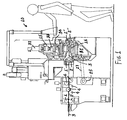
- the cutting and nibbling apparatus which has been generally indicated by the reference number 10, is designed for processing strip sheet metal elements 3, as supplied by coils.
- Said sheet metal elements in particular, which are delivered by a bobbin or coil, are driven by pairs of overlapped rollers 1 and 2, 1' and 2', 1" and 2".
- the apparatus 10 comprises moreover a plurality of offset rollers 4 provided for performing a series of folding and counter-folding operations, to provide the sheet metal element 3 in a perfectly flat condition.
- the sheet metal element feeding movement is performed in a continuous manner, with intermittent feeding steps, stop steps and also backward movement steps.
- the device for unwinding the coil is synchronized with the feed, stop and back movements of the sheet metal element 3.
- the apparatus 10 comprises furthermore two beams 11 and 12, which are transversely arranged with respect to the sheet metal feeding direction, at the top and bottom respectively of said sheet metal element.
- the beams 11 and 12 support cross guides 13 and 14, parallel to the first, which support the movable operating heads 15 and 16.
- Said operating or machining heads in particular, can be driven parallel to the beams 11 and 12 and in a cross direction with respect to the sheet metal element driving direction.
- Said operating or machining heads 15 and 16 can turn about a vertical machining axis, which can be transversely displaced, and being provided with a plurality of punch elements, arranged with a circular arrangement, designed for cooperating with corresponding dies applied to the bottom head 16.
- the machining heads 15 and 16 are rotatively driven by brushless motors 17 and 18.
- the cutting and nibbling apparatus also comprises a geared motor unit 19, the shaft 19' of which supports a toothed pulley 20, entraining a toothed belt 21.
- the toothed belt 21 in particular, rotatively drives a second toothed pulley 22, keyed on the shaft 23.
- Said shaft 23 longitudinally drives the sheet metal element 3, by operating a pair of feeding rollers 1, 2, which are connected with other pairs of feeding and pulling rollers 1', 2' and 1", 2".
- the brushless motor assembly 25 comprises a further toothed pulley 26, entraining a toothed pulley 27 thereon, said toothed pulley 27 in turn rotatively driving a further pulley 28.
- the pulley 28, as shown, is keyed on a screw element 29 engaging with a scroll element 30, which operatively drives a top punch bearing head 15, by causing said head 15 to translate along guide elements 13.
- the screw 29 cooperates with a second scroll element 31, which operatively drives the bottom die bearing head 16.
- the subject apparatus comprises furthermore a hydraulic cylinder 32, which vertically drives a wing element 33 having, at the bottom thereof, an eccentric lug 34.
- Said wing 33 selectively presses a punch element 36, which is radially arranged against the corresponding die therefor.
- the wing 33 in particular, is adapted to freely rotate, as entrained by the rotary head 15.
- the wing 33 in its lowering movement, will engage the eccentric lug 34 in a cavity corresponding to the punch element 36 to be driven.
- the wing 33 and its eccentric lug 34, engaging with a said punch element 36 are rotatively driven by the rotary movement of the head 15.
- the feeding movements of the sheet metal element, as well as the cross translating movements of the heads 15 and 16 and their rotary movements are controlled and timed or synchronized by a digital control central unit.
- the apparatus according to the invention has been specifically designed for machining or processing a sheet metal element which is continuously supplied to said apparatus and which is provided in coil form.
- inventive apparatus in addition to machining sheet metal elements, can also be used for performing a plurality of different mechanical operations on different material coils or sheets, such as wood, plywood and multi-layer wood material, plastics material, aggregated materials or any materials in strip or sheet form.
Claims (17)
- , Vorrichtung zum Schneiden und Nibbeln von Blechelementen in Spulenform, wobei die Vorrichtung Ziehvorrichtungen zum Ziehen der Blechelemente, die von einer Spule oder Walze geliefert und von einem Paar überlappender Walzen (1) und (1), (1') und (2') und (1") und (2") angetrieben sind, umfasst, wobei das Blechelement intermittierend gestoppt und rückwärts bewegt werden kann, wobei das Blechelement von einem Bearbeitungskopf (15) und einem Bearbeitungskopf (16) bearbeitet wird, die über und unter dem Blechelement eingerichtet sind und quer zu der 2uführrichtung des Blechelements angetrieben werden können, dadurch gekennzeichnet, dass die Vorrichtung (10) ferner eine Vielzahl von Offsetwalzen umfasst, die eine Reihe von Falt- und Gegenfaltvorgängen durchführen, um das Blechelement in einem perfekt flachen Zustand zu liefern, und dass die Bearbeitungsköpfe parallel zu den Balken und quer zu der Blechzuführrichtung angetrieben sind.
- Vorrichtung nach Anspruch 1, dadurch gekennzeichnet, dass das Blechelement ununterbrochen mit intermittierenden Zuführ-, Stopp- und Rückwärtsbewegungsschritten zugeführt wird.
- Vorrichtung nach Anspruch 1 und 2, dadurch gekennzeichnet, dass die Vorrichtung ferner Balken (11) und (12) umfasst, die Querführungselemente (13) und (14) parallel zu den Balken stützen, die wiederum die beweglichen Bearbeitungsköpfe (15) und (16) stützen.
- Vorrichtung nach einem oder mehreren der vorhergehenden Ansprüche, dadurch gekennzeichnet, dass die Bearbeitungsköpfe (15) und (16) um eine Bearbeitungsachse drehen können, die wiederum quer angetrieben werden kann.
- Vorrichtung nach einem oder mehreren der vorhergehenden Ansprüche, dadurch gekennzeichnet, dass die Bearbeitungsköpfe (15) und (16) eine Vielzahl von kreisförmig angeordneten Stanzelementen (36) umfassen, die mit entsprechenden Gesenkelementen zusammen arbeiten, die an den unteren Bearbeitungskopf (16) angelegt werden.
- Vorrichtung nach einem oder mehreren der vorhergehenden Ansprüche, dadurch gekennzeichnet, dass die Bearbeitungsköpfe (15) und (16) in Drehung von bürstenlosen Motoren (17) und (18) angetrieben werden.
- Vorrichtung nach einem oder mehreren der vorhergehenden Ansprüche, dadurch gekennzeichnet, dass die Vorrichtung ferner einen Getriebemotor (19) umfasst, wobei der Getriebemotor (19) eine Welle (19') hat, die eine Zahnscheibe (20) stützt, die einen Zahnriemen (21) antreibt.
- Vorrichtung nach einem oder mehreren der vorhergehenden Ansprüche, dadurch gekennzeichnet, dass der Zahnriemen eine zweite Scheibe (22) in Drehung antreibt, die in eine Stützwelle (23) eingreift.
- Vorrichtung nach einem oder mehreren der vorhergehenden Ansprüche, dadurch gekennzeichnet, dass die Welle (23) längs das Blechelement antreibt, indem sie das Paar Antriebswalzen (1), (2) antreibt, dessen Walzen mit den anderen Paaren von Zuführ- und Antriebswalzen (1') , (2') und (1"), (2") gekoppelt sind.
- Vorrichtung nach einem oder mehreren der vorhergehenden Ansprüche, dadurch gekennzeichnet, dass die Vorrichtung einen bürstenlosen Motorblock (25) mit einer Zahnscheibe (26) umfasst, die einen Zahnriemen (27) antreibt, welcher wiederum eine Zahnscheibe (28) in Drehung antreibt, die in eine Schnecke (29) eingreift.
- Vorrichtung nach einem oder mehreren der vorhergehenden Ansprüche, dadurch gekennzeichnet, dass die Schnecke (29) in ein Spiralelement (30) eingreift, das einen oberen Stanzentragkopf (15) wirkend antreibt, so dass der Kopf (15) entlang seiner Führungselemente (13) verschoben wird.
- vorrichtung nach einem oder mehreren der vorhergehenden Ansprüche, dadurch gekennzeichnet, dass die Schnecke (29) mit einem zweiten Spiralelement (31) zusammen arbeitet, das den unteren Gesenktragkopf (16) wirkend antreibt.
- Vorrichtung nach einem oder mehreren der vorhergehenden Ansprüche, dadurch gekennzeichnet, dass die Vorrichtung ferner einen Hydraulikzylinder (32) umfasst, der senkrecht einen Flügel (33) antreibt, an dessen Bodenabschnitt sich ein exzentrierter Bügel (34) befindet, und der selektiv eine radial angeordnete Stanze gegen ein entsprechendes Gesenkelement drückt.
- Vorrichtung nach einem oder mehreren der vorhergehenden Ansprüche, dadurch gekennzeichnet, dass der Flügel (33) durch den Bearbeitungskopf (15) angetrieben frei drehen kann.
- Vorrichtung nach einem oder mehreren der vorhergehenden Ansprüche, dadurch gekennzeichnet, dass der Flügel (33), wenn er gesenkt wird, den exzentrierten Bügel (34) in einen Hohlraum einfügt, der einem zu betätigenden Stanzelement (36) entspricht.
- vorrichtung nach einem oder mehreren der vorhergehenden Ansprüche, dadurch gekennzeichnet, dass der Flügel (33) und der exzentrische Bügel (34), die in ein Stanzelement (36) eingreifen, in Drehung von einer Drehbewegung des Bearbeitungskopfs angetrieben werden.
- Vorrichtung nach einem oder mehreren der vorhergehenden Ansprüche, dadurch gekennzeichnet, dass die Bewegungen des Blechelements und die Bearbeitungsköpfe von einer numerischen Steuerzentraleinheit gesteuert und getaktet werden.
Applications Claiming Priority (3)
| Application Number | Priority Date | Filing Date | Title |
|---|---|---|---|
| ITMI20021096 | 2002-05-21 | ||
| IT2002MI001096 ITMI20021096A1 (it) | 2002-05-21 | 2002-05-21 | Macchina atta ad eseguire il taglio e la roditura di una lamiera in coils |
| PCT/IT2003/000236 WO2003097271A1 (en) | 2002-05-21 | 2003-04-15 | Apparatus for cutting and nibbling a sheet metal in coil form |
Publications (2)
| Publication Number | Publication Date |
|---|---|
| EP1507609A1 EP1507609A1 (de) | 2005-02-23 |
| EP1507609B1 true EP1507609B1 (de) | 2005-11-02 |
Family
ID=11449949
Family Applications (1)
| Application Number | Title | Priority Date | Filing Date |
|---|---|---|---|
| EP03720878A Expired - Lifetime EP1507609B1 (de) | 2002-05-21 | 2003-04-15 | Vorrichtung zum schneiden und nibbeln eines bleches in spulenform |
Country Status (9)
| Country | Link |
|---|---|
| US (1) | US7065997B2 (de) |
| EP (1) | EP1507609B1 (de) |
| AT (1) | ATE308394T1 (de) |
| AU (1) | AU2003224452A1 (de) |
| CA (1) | CA2475250C (de) |
| DE (1) | DE60302153T2 (de) |
| ES (1) | ES2248741T3 (de) |
| IT (1) | ITMI20021096A1 (de) |
| WO (1) | WO2003097271A1 (de) |
Cited By (1)
| Publication number | Priority date | Publication date | Assignee | Title |
|---|---|---|---|---|
| CN110076235A (zh) * | 2019-05-23 | 2019-08-02 | 张潇 | 一种防止冲压模具中料带上拱的拉料设备 |
Families Citing this family (7)
| Publication number | Priority date | Publication date | Assignee | Title |
|---|---|---|---|---|
| WO2004105978A1 (de) * | 2003-05-30 | 2004-12-09 | Emitec Gesellschaft Für Emissionstechnologie Mbh | Herstellung eines strukturierten bleches für abgasbehandlungseinrichtungen |
| DE102004001419A1 (de) * | 2003-05-30 | 2004-12-16 | Emitec Gesellschaft Für Emissionstechnologie Mbh | Herstellung eines strukturierten Bleches für Abgasbehandlungseinrichtungen |
| DE102004017343A1 (de) | 2004-04-06 | 2005-11-03 | Muhr Und Bender Kg | Verfahren zur Herstellung von Profilen mit in Längsrichtung veränderlichem Querschnitt |
| IT1391092B1 (it) * | 2008-08-01 | 2011-11-18 | Produtech S R L | Macchina perfezionata atta ad eseguire il taglio, la punzonatura e la roditura di lamiere. |
| ES2398175B1 (es) * | 2010-01-29 | 2014-01-17 | Vicente Escolano S.L. | Máquina troqueladora de láminas metálicas. |
| US9279283B2 (en) * | 2010-07-16 | 2016-03-08 | Ged Integrated Solutions, Inc. | Automated spacer frame fabrication |
| CN106984689B (zh) * | 2017-04-21 | 2019-01-04 | 漳州利阳机械设备有限公司 | 片状钢材起吊裁切一体化装置及其方法 |
Family Cites Families (10)
| Publication number | Priority date | Publication date | Assignee | Title |
|---|---|---|---|---|
| US3124290A (en) * | 1960-10-27 | 1964-03-10 | figure | |
| US3880020A (en) * | 1973-06-06 | 1975-04-29 | Goodyear Tire & Rubber | Making blades for tire curing molds |
| US4138913A (en) * | 1977-09-26 | 1979-02-13 | Vamco Machine And Tool, Inc. | Punch press feeding apparatus |
| FR2471231A1 (fr) | 1979-12-12 | 1981-06-19 | Weingarten Ag Maschf | Dispositif de decoupage pour une presse pour le decoupage de flans ou de segments dans un materiau en bande ou ruban, tel que feuillard ou similaire, qui passe par intermittence a travers l'outil |
| JPS60141342A (ja) | 1983-12-28 | 1985-07-26 | Orii Jidoki Seisakusho:Kk | コイル材2次元送り装置 |
| GB8420343D0 (en) | 1984-08-10 | 1984-09-12 | Workman J | Metal pressing and stamping |
| EP0196466B1 (de) * | 1985-03-01 | 1991-04-24 | Sumitomo Metal Industries, Ltd. | Verfahren und Vorrichtung zum Zuführen von Material zu einer Warmschmiedemaschine |
| US4887502A (en) * | 1986-12-08 | 1989-12-19 | Red Bud Industries, Inc. | Machine for slitting metal sheet |
| US5088181A (en) * | 1990-10-09 | 1992-02-18 | The Boeing Company | Sheet metal part machining system |
| US6857350B1 (en) * | 1999-07-22 | 2005-02-22 | Red Bud Industries, Inc. | Appliance and process for reducing distortion of slit metal sheet |
-
2002
- 2002-05-21 IT IT2002MI001096 patent/ITMI20021096A1/it unknown
-
2003
- 2003-04-15 EP EP03720878A patent/EP1507609B1/de not_active Expired - Lifetime
- 2003-04-15 AT AT03720878T patent/ATE308394T1/de not_active IP Right Cessation
- 2003-04-15 US US10/500,743 patent/US7065997B2/en not_active Expired - Lifetime
- 2003-04-15 DE DE2003602153 patent/DE60302153T2/de not_active Expired - Lifetime
- 2003-04-15 WO PCT/IT2003/000236 patent/WO2003097271A1/en not_active Application Discontinuation
- 2003-04-15 AU AU2003224452A patent/AU2003224452A1/en not_active Abandoned
- 2003-04-15 ES ES03720878T patent/ES2248741T3/es not_active Expired - Lifetime
- 2003-04-15 CA CA2475250A patent/CA2475250C/en not_active Expired - Fee Related
Cited By (1)
| Publication number | Priority date | Publication date | Assignee | Title |
|---|---|---|---|---|
| CN110076235A (zh) * | 2019-05-23 | 2019-08-02 | 张潇 | 一种防止冲压模具中料带上拱的拉料设备 |
Also Published As
| Publication number | Publication date |
|---|---|
| EP1507609A1 (de) | 2005-02-23 |
| ITMI20021096A1 (it) | 2003-11-21 |
| ES2248741T3 (es) | 2006-03-16 |
| US20050028573A1 (en) | 2005-02-10 |
| US7065997B2 (en) | 2006-06-27 |
| CA2475250C (en) | 2011-01-11 |
| AU2003224452A1 (en) | 2003-12-02 |
| ATE308394T1 (de) | 2005-11-15 |
| CA2475250A1 (en) | 2003-11-27 |
| ITMI20021096A0 (it) | 2002-05-21 |
| WO2003097271A1 (en) | 2003-11-27 |
| DE60302153T2 (de) | 2006-08-10 |
| DE60302153D1 (de) | 2005-12-08 |
Similar Documents
| Publication | Publication Date | Title |
|---|---|---|
| KR101621064B1 (ko) | 프로파일의 펀칭 및 노칭 자동가공장치 | |
| JP6101546B2 (ja) | 裁断装置 | |
| KR101621065B1 (ko) | 프로파일의 펀칭 및 노칭 자동가공장치 | |
| EP1507609B1 (de) | Vorrichtung zum schneiden und nibbeln eines bleches in spulenform | |
| US5246533A (en) | Apparatus for press-bonding tape onto edges of workpiece | |
| US20060027066A1 (en) | Web forming machine | |
| WO1993003893A1 (en) | Linear punch press | |
| CN104290134A (zh) | 模切加工设备及模切加工方法 | |
| WO2005009697A1 (en) | Machine for manufacturing cardboard blanks | |
| CN212859771U (zh) | 橡胶垫冲切一体机 | |
| CN207495648U (zh) | 一种商标裁切装置 | |
| CN210237976U (zh) | 一种手套生产设备 | |
| CN210795205U (zh) | 一种基站天线绝缘片生产线 | |
| CN210061294U (zh) | 一种用于半切裁断的冲头、及一种移动式半切裁断机 | |
| JPH07314242A (ja) | 鋼材の自動搬送加工装置 | |
| CN110695488A (zh) | 一种仿形切割机用工作台 | |
| CN219325328U (zh) | 一种双端分切开槽机 | |
| US10369615B2 (en) | Method of joining strip-shaped sheets | |
| CN215280112U (zh) | 一种液压摆式剪切机用精密进给的齿轮式匀速走料机构 | |
| CN211053837U (zh) | 一种推纸机构、输送装置和卷筒纸切纸机 | |
| CN214641090U (zh) | 一种双头自动送料切割机 | |
| KR100394789B1 (ko) | 철판용 가공장치 | |
| CN216139048U (zh) | 一种超声波冲孔剪切机 | |
| CN218079910U (zh) | 用于金属杆材的冲孔装置 | |
| JP3762192B2 (ja) | プレス機械のワーク搬送装置 |
Legal Events
| Date | Code | Title | Description |
|---|---|---|---|
| PUAI | Public reference made under article 153(3) epc to a published international application that has entered the european phase |
Free format text: ORIGINAL CODE: 0009012 |
|
| 17P | Request for examination filed |
Effective date: 20040701 |
|
| AK | Designated contracting states |
Kind code of ref document: A1 Designated state(s): AT BE BG CH CY CZ DE DK EE ES FI FR GB GR HU IE IT LI LU MC NL PT RO SE SI SK TR |
|
| AX | Request for extension of the european patent |
Extension state: AL LT LV MK |
|
| GRAP | Despatch of communication of intention to grant a patent |
Free format text: ORIGINAL CODE: EPIDOSNIGR1 |
|
| GRAS | Grant fee paid |
Free format text: ORIGINAL CODE: EPIDOSNIGR3 |
|
| GRAA | (expected) grant |
Free format text: ORIGINAL CODE: 0009210 |
|
| AK | Designated contracting states |
Kind code of ref document: B1 Designated state(s): AT BE BG CH CY CZ DE DK EE ES FI FR GB GR HU IE IT LI LU MC NL PT RO SE SI SK TR |
|
| PG25 | Lapsed in a contracting state [announced via postgrant information from national office to epo] |
Ref country code: RO Free format text: LAPSE BECAUSE OF FAILURE TO SUBMIT A TRANSLATION OF THE DESCRIPTION OR TO PAY THE FEE WITHIN THE PRESCRIBED TIME-LIMIT Effective date: 20051102 Ref country code: LI Free format text: LAPSE BECAUSE OF FAILURE TO SUBMIT A TRANSLATION OF THE DESCRIPTION OR TO PAY THE FEE WITHIN THE PRESCRIBED TIME-LIMIT Effective date: 20051102 Ref country code: IT Free format text: LAPSE BECAUSE OF FAILURE TO SUBMIT A TRANSLATION OF THE DESCRIPTION OR TO PAY THE FEE WITHIN THE PRESCRIBED TIME-LIMIT;WARNING: LAPSES OF ITALIAN PATENTS WITH EFFECTIVE DATE BEFORE 2007 MAY HAVE OCCURRED AT ANY TIME BEFORE 2007. THE CORRECT EFFECTIVE DATE MAY BE DIFFERENT FROM THE ONE RECORDED. Effective date: 20051102 Ref country code: NL Free format text: LAPSE BECAUSE OF FAILURE TO SUBMIT A TRANSLATION OF THE DESCRIPTION OR TO PAY THE FEE WITHIN THE PRESCRIBED TIME-LIMIT Effective date: 20051102 Ref country code: CH Free format text: LAPSE BECAUSE OF FAILURE TO SUBMIT A TRANSLATION OF THE DESCRIPTION OR TO PAY THE FEE WITHIN THE PRESCRIBED TIME-LIMIT Effective date: 20051102 Ref country code: AT Free format text: LAPSE BECAUSE OF FAILURE TO SUBMIT A TRANSLATION OF THE DESCRIPTION OR TO PAY THE FEE WITHIN THE PRESCRIBED TIME-LIMIT Effective date: 20051102 Ref country code: CZ Free format text: LAPSE BECAUSE OF FAILURE TO SUBMIT A TRANSLATION OF THE DESCRIPTION OR TO PAY THE FEE WITHIN THE PRESCRIBED TIME-LIMIT Effective date: 20051102 Ref country code: FI Free format text: LAPSE BECAUSE OF FAILURE TO SUBMIT A TRANSLATION OF THE DESCRIPTION OR TO PAY THE FEE WITHIN THE PRESCRIBED TIME-LIMIT Effective date: 20051102 Ref country code: BE Free format text: LAPSE BECAUSE OF FAILURE TO SUBMIT A TRANSLATION OF THE DESCRIPTION OR TO PAY THE FEE WITHIN THE PRESCRIBED TIME-LIMIT Effective date: 20051102 Ref country code: SI Free format text: LAPSE BECAUSE OF FAILURE TO SUBMIT A TRANSLATION OF THE DESCRIPTION OR TO PAY THE FEE WITHIN THE PRESCRIBED TIME-LIMIT Effective date: 20051102 Ref country code: SK Free format text: LAPSE BECAUSE OF FAILURE TO SUBMIT A TRANSLATION OF THE DESCRIPTION OR TO PAY THE FEE WITHIN THE PRESCRIBED TIME-LIMIT Effective date: 20051102 |
|
| REG | Reference to a national code |
Ref country code: GB Ref legal event code: FG4D |
|
| REG | Reference to a national code |
Ref country code: CH Ref legal event code: EP |
|
| REF | Corresponds to: |
Ref document number: 60302153 Country of ref document: DE Date of ref document: 20051208 Kind code of ref document: P |
|
| PG25 | Lapsed in a contracting state [announced via postgrant information from national office to epo] |
Ref country code: SE Free format text: LAPSE BECAUSE OF FAILURE TO SUBMIT A TRANSLATION OF THE DESCRIPTION OR TO PAY THE FEE WITHIN THE PRESCRIBED TIME-LIMIT Effective date: 20060202 Ref country code: GR Free format text: LAPSE BECAUSE OF FAILURE TO SUBMIT A TRANSLATION OF THE DESCRIPTION OR TO PAY THE FEE WITHIN THE PRESCRIBED TIME-LIMIT Effective date: 20060202 Ref country code: BG Free format text: LAPSE BECAUSE OF FAILURE TO SUBMIT A TRANSLATION OF THE DESCRIPTION OR TO PAY THE FEE WITHIN THE PRESCRIBED TIME-LIMIT Effective date: 20060202 Ref country code: DK Free format text: LAPSE BECAUSE OF FAILURE TO SUBMIT A TRANSLATION OF THE DESCRIPTION OR TO PAY THE FEE WITHIN THE PRESCRIBED TIME-LIMIT Effective date: 20060202 |
|
| REG | Reference to a national code |
Ref country code: ES Ref legal event code: FG2A Ref document number: 2248741 Country of ref document: ES Kind code of ref document: T3 |
|
| PG25 | Lapsed in a contracting state [announced via postgrant information from national office to epo] |
Ref country code: PT Free format text: LAPSE BECAUSE OF FAILURE TO SUBMIT A TRANSLATION OF THE DESCRIPTION OR TO PAY THE FEE WITHIN THE PRESCRIBED TIME-LIMIT Effective date: 20060403 |
|
| PG25 | Lapsed in a contracting state [announced via postgrant information from national office to epo] |
Ref country code: IE Free format text: LAPSE BECAUSE OF NON-PAYMENT OF DUE FEES Effective date: 20060417 |
|
| PG25 | Lapsed in a contracting state [announced via postgrant information from national office to epo] |
Ref country code: MC Free format text: LAPSE BECAUSE OF NON-PAYMENT OF DUE FEES Effective date: 20060430 |
|
| NLV1 | Nl: lapsed or annulled due to failure to fulfill the requirements of art. 29p and 29m of the patents act | ||
| PG25 | Lapsed in a contracting state [announced via postgrant information from national office to epo] |
Ref country code: HU Free format text: LAPSE BECAUSE OF FAILURE TO SUBMIT A TRANSLATION OF THE DESCRIPTION OR TO PAY THE FEE WITHIN THE PRESCRIBED TIME-LIMIT Effective date: 20060503 |
|
| REG | Reference to a national code |
Ref country code: CH Ref legal event code: PL |
|
| ET | Fr: translation filed | ||
| PLBE | No opposition filed within time limit |
Free format text: ORIGINAL CODE: 0009261 |
|
| STAA | Information on the status of an ep patent application or granted ep patent |
Free format text: STATUS: NO OPPOSITION FILED WITHIN TIME LIMIT |
|
| 26N | No opposition filed |
Effective date: 20060803 |
|
| REG | Reference to a national code |
Ref country code: IE Ref legal event code: MM4A |
|
| PG25 | Lapsed in a contracting state [announced via postgrant information from national office to epo] |
Ref country code: EE Free format text: LAPSE BECAUSE OF FAILURE TO SUBMIT A TRANSLATION OF THE DESCRIPTION OR TO PAY THE FEE WITHIN THE PRESCRIBED TIME-LIMIT Effective date: 20051102 |
|
| PG25 | Lapsed in a contracting state [announced via postgrant information from national office to epo] |
Ref country code: TR Free format text: LAPSE BECAUSE OF FAILURE TO SUBMIT A TRANSLATION OF THE DESCRIPTION OR TO PAY THE FEE WITHIN THE PRESCRIBED TIME-LIMIT Effective date: 20051102 Ref country code: LU Free format text: LAPSE BECAUSE OF NON-PAYMENT OF DUE FEES Effective date: 20060415 |
|
| PG25 | Lapsed in a contracting state [announced via postgrant information from national office to epo] |
Ref country code: CY Free format text: LAPSE BECAUSE OF FAILURE TO SUBMIT A TRANSLATION OF THE DESCRIPTION OR TO PAY THE FEE WITHIN THE PRESCRIBED TIME-LIMIT Effective date: 20051102 |
|
| REG | Reference to a national code |
Ref country code: FR Ref legal event code: PLFP Year of fee payment: 14 |
|
| REG | Reference to a national code |
Ref country code: FR Ref legal event code: PLFP Year of fee payment: 15 |
|
| REG | Reference to a national code |
Ref country code: FR Ref legal event code: PLFP Year of fee payment: 16 |
|
| PGFP | Annual fee paid to national office [announced via postgrant information from national office to epo] |
Ref country code: FR Payment date: 20200427 Year of fee payment: 18 |
|
| PGFP | Annual fee paid to national office [announced via postgrant information from national office to epo] |
Ref country code: GB Payment date: 20200417 Year of fee payment: 18 |
|
| PGFP | Annual fee paid to national office [announced via postgrant information from national office to epo] |
Ref country code: DE Payment date: 20200630 Year of fee payment: 18 Ref country code: ES Payment date: 20200703 Year of fee payment: 18 |
|
| REG | Reference to a national code |
Ref country code: DE Ref legal event code: R119 Ref document number: 60302153 Country of ref document: DE |
|
| GBPC | Gb: european patent ceased through non-payment of renewal fee |
Effective date: 20210415 |
|
| PG25 | Lapsed in a contracting state [announced via postgrant information from national office to epo] |
Ref country code: DE Free format text: LAPSE BECAUSE OF NON-PAYMENT OF DUE FEES Effective date: 20211103 Ref country code: FR Free format text: LAPSE BECAUSE OF NON-PAYMENT OF DUE FEES Effective date: 20210430 Ref country code: GB Free format text: LAPSE BECAUSE OF NON-PAYMENT OF DUE FEES Effective date: 20210415 |
|
| REG | Reference to a national code |
Ref country code: ES Ref legal event code: FD2A Effective date: 20220701 |
|
| PG25 | Lapsed in a contracting state [announced via postgrant information from national office to epo] |
Ref country code: ES Free format text: LAPSE BECAUSE OF NON-PAYMENT OF DUE FEES Effective date: 20210416 |