EP1506116B1 - Absenkbares gepäckfach mit rückseitiger kraftunterstützungseinrichtung - Google Patents
Absenkbares gepäckfach mit rückseitiger kraftunterstützungseinrichtung Download PDFInfo
- Publication number
- EP1506116B1 EP1506116B1 EP03752767A EP03752767A EP1506116B1 EP 1506116 B1 EP1506116 B1 EP 1506116B1 EP 03752767 A EP03752767 A EP 03752767A EP 03752767 A EP03752767 A EP 03752767A EP 1506116 B1 EP1506116 B1 EP 1506116B1
- Authority
- EP
- European Patent Office
- Prior art keywords
- luggage compartment
- force
- assistance
- transmitting device
- flexible
- Prior art date
- Legal status (The legal status is an assumption and is not a legal conclusion. Google has not performed a legal analysis and makes no representation as to the accuracy of the status listed.)
- Expired - Lifetime
Links
- 230000005540 biological transmission Effects 0.000 description 13
- 230000010354 integration Effects 0.000 description 2
- 230000000903 blocking effect Effects 0.000 description 1
- 230000000694 effects Effects 0.000 description 1
- 230000002349 favourable effect Effects 0.000 description 1
- 238000009434 installation Methods 0.000 description 1
- 239000000463 material Substances 0.000 description 1
- 229910001220 stainless steel Inorganic materials 0.000 description 1
- 239000010935 stainless steel Substances 0.000 description 1
Images



Classifications
-
- B—PERFORMING OPERATIONS; TRANSPORTING
- B64—AIRCRAFT; AVIATION; COSMONAUTICS
- B64D—EQUIPMENT FOR FITTING IN OR TO AIRCRAFT; FLIGHT SUITS; PARACHUTES; ARRANGEMENT OR MOUNTING OF POWER PLANTS OR PROPULSION TRANSMISSIONS IN AIRCRAFT
- B64D11/00—Passenger or crew accommodation; Flight-deck installations not otherwise provided for
- B64D11/003—Stowage devices for passengers' personal luggage
-
- Y—GENERAL TAGGING OF NEW TECHNOLOGICAL DEVELOPMENTS; GENERAL TAGGING OF CROSS-SECTIONAL TECHNOLOGIES SPANNING OVER SEVERAL SECTIONS OF THE IPC; TECHNICAL SUBJECTS COVERED BY FORMER USPC CROSS-REFERENCE ART COLLECTIONS [XRACs] AND DIGESTS
- Y02—TECHNOLOGIES OR APPLICATIONS FOR MITIGATION OR ADAPTATION AGAINST CLIMATE CHANGE
- Y02T—CLIMATE CHANGE MITIGATION TECHNOLOGIES RELATED TO TRANSPORTATION
- Y02T50/00—Aeronautics or air transport
- Y02T50/40—Weight reduction
Definitions
- the present invention relates to a lowerable luggage compartment, in particular for a passenger aircraft, with a power assistance device for providing an assisting force when opening and / or closing the luggage compartment.
- Lowerable overhead luggage compartments in aircraft are known, see DE 196 17 657 A1.
- DE 41 30 644 C2 a lowerable overhead luggage compartment of a passenger aircraft with guide systems in the form of four-bar linkages on each side wall of the luggage compartment and a gas spring for each guide system, which provides a support force for pivoting the luggage compartment according to the weight of the luggage compartment.
- An adjusting detects during loading the weight of the luggage compartment and acts via an adjustment connection to the force application point of the gas spring, in order to achieve a respective loading weight of the luggage compartment corresponding adjustment.
- a lowerable overhead luggage compartment which also has on its two side walls each have a guide system with an associated gas spring.
- the gas spring is in operative connection with a support device which provides a support force adapted to the weight of the luggage compartment for pivoting up the luggage compartment.
- a blocking device allows a locking of the support device.
- DE 44 46 772 C1 finally describes a device for guiding a lowerable overhead luggage compartment with two arranged on both sides of the side walls of the luggage compartment four-bar linkages and a spring system per four-bar linkage to support the Hochschwenkamba the luggage compartment.
- a arranged within the luggage compartment scale plate acts on below the scale plate arranged pressure transducer, which in turn are connected via at least one Verstelltell with an adjusting cylinder, which acts on an adjusting device for moving the force application point of the spring system to move it depending on the weight of the luggage compartment, so a counteracting torque adapted to the load moment resulting from the weight of the luggage compartment is provided.
- the invention has for its object to improve a lowerable luggage compartment with a force support device to the effect that the usable volume of the luggage compartment is increased and that the unit of luggage compartment and power assistance device with improved maintainability is easier than before.
- the inventive solution is characterized in that only a single, decoupled from the leadership of the luggage compartment power assistance device is arranged on the back of the luggage compartment and that the force support module running as a separate housing force support device can be used in conjunction with various types of luggage compartments and above Moreover, in the case of failure as a unit, it is easily interchangeable and thus very easy to maintain.
- the gap between laterally adjacent storage compartments can be made narrower.
- the inner volume of a luggage compartment can therefore be increased without increasing its external dimensions.
- the solution according to the invention is also significantly less susceptible to asymmetric loading of the luggage compartment. Furthermore, the solution according to the invention is weight-saving and less expensive because all components of the power assistance device are needed only once and not twice.
- a gas spring preferably generates the required assist force.
- the force provided by the power assistance device is transmitted to the luggage compartment by means of a single flexible power transmission device.
- the flexible power transmission device acts on or near the top of the luggage compartment.
- the flexible power transmission device can attack at only one point of the luggage compartment or at several points.
- the flexible power transmission device is designed such that it has at least one force application point on the luggage compartment has, with respect to the width extension of the luggage compartment at least near the center.
- the point of force application or the points of application of force are chosen so that they are arranged at or near a front edge of the top of the luggage compartment.
- each at least in one plane flexible power transmission means is suitable.
- the flexible power transmission device is a guided over at least one pulley rope.
- the rope may be a rope made, for example, of stainless steel, but it may also, in particular for further weight spatter, be a suitable plastic rope or a rope made of another material suitable for the purpose mentioned.
- the flexible power transmission device is an at least once deflected chain.
- the flexible power transmission device is a Bowden cable. Due to the shell in which a Bowden cable is guided, no separate deflection is required in the latter embodiment, but the Bowden cable can be installed directly from the power assistance device to the desired point of force application on the luggage compartment.
- the power assistance device can in principle be attached at any location behind the back of the luggage compartment.
- the power assist device is attached to a housing in which the luggage compartment is guided. In a passenger aircraft, this housing is connected to the supporting structure of the aircraft.
- the power assist device is designed so that the Support force depending on the loading weight of the luggage compartment changes. A user of the luggage compartment must then always spend a substantially equal force regardless of the loading condition of the luggage compartment to close the luggage compartment.
- FIG. 1 a generally designated 10 lowerable overhead luggage compartment of an aircraft not shown is shown. Behind the back of the luggage compartment 10 is mounted as a power assist module 12 power assist device which transmits an assisting force to the luggage compartment 10 by means of a flexible power transmission cable 14 to keep the opening and closing of the luggage compartment 10 necessary force at a low level, regardless of whether the luggage compartment 12 is empty or fully loaded.
- the cable 14 is attached at its one end in the power assist module 12 and at the other end to the luggage compartment 10 and guided over two here only hinted deflection rollers 16, 16 '.
- the luggage compartment 10 is received in a housing 18, which in a manner not shown on the supporting structure of the aircraft is attached.
- the luggage compartment 10 is in the housing 18 by means of two guide means 20 and 20 ', which are arranged on one or the other side of the luggage compartment 10 and in each case two levers 21, 22 and 21', 22 ', guided such that it swings out when opening out of the housing 18 down and at the same time lowers.
- the power assisting module 12 is completely embedded in a rear wall of the housing 18.
- the power assist module 12 is arranged approximately in the middle of the rear wall of the housing 18.
- the power assist module 12 is formed as a separate unit to handle and even has a housing 24 in which all necessary to provide the desired support force components are housed.
- the power assistance module 12 is capable of adjusting the provided assistance force to the loading condition of the luggage compartment 10 so that a user must apply an at least substantially equal, load-independent closing force to push and close the overhead compartment 10.
- the cable 14 is suitably attached.
- the force application point P is located in the middle between the two sides of the luggage compartment 10 and near a front edge 28 of the top 26 of the luggage compartment 10.
- the force application point P can also be arranged away from the front edge 28, for example approximately in the middle of the upper side 26 of the luggage compartment 10 as shown in FIG.
- Embodiments not shown may have multiple force application points, and instead of the cable 14 other flexible power transmission devices may be used, for example, chains or Bowden cables.
Landscapes
- Engineering & Computer Science (AREA)
- Aviation & Aerospace Engineering (AREA)
- Vehicle Step Arrangements And Article Storage (AREA)
- Packages (AREA)
- Installation Of Indoor Wiring (AREA)
- Superstructure Of Vehicle (AREA)
- Fittings On The Vehicle Exterior For Carrying Loads, And Devices For Holding Or Mounting Articles (AREA)
Description
- Die vorliegende Erfindung betrifft ein absenkbares Gepäckfach, insbesondere für ein Passagierflugzeug, mit einer Kraftunterstützungseinrichtung zur Bereitstellung einer Unterstützungskraft beim Öffnen und/oder Schließen des Gepäckfaches.
- Absenkbare Überkopf-Gepäckfächer in Flugzeugen sind bekannt, siehe DE 196 17 657 A1. So beschreibt z.B. die DE 41 30 644 C2 ein absenkbares Überkopf-Gepäckfach eines Passagierflugzeuges mit Führungssystemen in Form von Gelenkvierecken an jeder Seitenwand des Gepäckfaches und einer Gasdruckfeder für jedes Führungssystem, die entsprechend dem Gewicht des Gepäckfaches eine Unterstützungskraft zum Hochschwenken des Gepäckfachs liefert. Eine Verstelleinrichtung erfasst während des Beladens das Gewicht des Gepäckfachs und wirkt über eine Verstellverbindung auf den Kraftangriffspunkt der Gasdruckfeder ein, um eine dem jeweiligen Beladegewicht des Gepäckfaches entsprechende Einstellung zu erzielen.
- Aus der DE 43 35 151 C2 ist ein absenkbares Überkopf-Gepäckfach bekannt, welches ebenfalls an seinen beiden Seitenwänden je ein Führungssystem mit einer zugeordneten Gasfeder aufweist. Die Gasfeder steht mit einer Unterstützungseinrichtung in Wirkverbindung, die eine dem Gewicht des Gepäckfaches angepasste Unterstützungskraft für das Hochschwenken des Gepäckfachs bereitstellt. Eine Blockiereinrichtung ermöglicht eine Verriegelung der Unterstützungseinrichtung.
- Die DE 44 46 772 C1 schließlich beschreibt eine Vorrichtung zum Führen eines absenkbaren Überkopf-Gepäckfaches mit zwei beidseitig an den Seitenwänden des Gepäckfaches angeordneten Gelenkvierecken und einem Federsystem je Gelenkviereck zur Unterstützung der Hochschwenkbewegung des Gepäckfaches. Eine innerhalb des Gepäckfaches angeordnete Waageplatte wirkt auf unterhalb der Waageplatte angeordnete Druckgeber, die ihrerseits über mindestens eine Verstellverbindung mit einem Verstellzylinder verbunden sind, der auf eine Verstelleinrichtung zum Verschieben des Kraftangriffspunktes des Federsystems einwirkt, um ihn in Abhängigkeit vom Gewicht des Gepäckfachs zu verschieben, so dass ein dem Lastmoment, das aus dem Gewicht des Gepäckfachs resultiert, angepasstes entgegenwirkendes Drehmoment bereitgestellt wird.
- Der Erfindung liegt die Aufgabe zugrunde, ein absenkbares Gepäckfach mit einer Kraftunterstützungseinrichtung dahingehend zu verbessern, dass das nutzbare Volumen des Gepäckfaches vergrößert ist und dass die Einheit aus Gepäckfach und Kraftunterstützungseinrichtung bei verbesserter Wartbarkeit leichter als bisher ist.
- Diese Aufgabe wird erfindungsgemäβ durch die Merkmale des Anspruchs 1 gelöst. Die Unteransprüche definieren weiter Ausführungsformen des Gegenstandes der Erfindung.
- Die erfindungsgemäße Lösung zeichnet sich dadurch aus, dass nur eine einzige, von der Führung des Gepäckfaches entkoppelte Kraftunterstützungseinrichtung auf der Rückseite des Gepäckfaches angeordnet ist und dass die als Kraftunterstützungsmodul mit einem eigenen Gehäuse ausgeführte Kraftunterstützungseinrichtung sich in Verbindung mit verschiedenen Typen von Gepäckfächem verwenden lässt und darüber hinaus im Fall eines Versagens als Einheit einfach austauschbar und somit sehr wartungsfreundlich ist. Durch die nur eine flexible Kraftübertragungseinrichtung kann der Spalt zwischen seitlich aneinander angrenzenden Gepäckfächern schmaler ausgeführt werden. Das innere Volumen eines Gepäckfaches kann deshalb ohne Vergrößerung seiner äußeren Abmessungen erhöht werden. Die erfindungsgemäße Lösung ist darüber hinaus deutlich weniger anfällig gegenüber einer asymmetrischen Belastung des Gepäckfaches. Ferner ist die erfindungsgemäße Lösung gewichtssparend und kostengünstiger, weil alle Bauteile der Kraftunterstützungseinrichtung nur einmal und nicht doppelt benötigt werden.
- In dem Kraftunterstützungsmodul erzeugt vorzugsweise eine Gasdruckfeder die geforderte Unterstützungskraft.
- Bei dem erfindungsgemäßen Gepäckfach wird die von der Kraftunterstützungseinrichtung bereitgestellte Kraft mittels einer einzigen flexiblen Kraftübertragungseinrichtung auf das Gepäckfach übertragen. Vorteilhaft greift die flexible Kraftübertragungseinrichtung an oder nahe der Oberseite des Gepäckfaches an. Die flexible Kraftübertragungseinrichtung kann an nur einer Stelle des Gepäckfaches oder auch an mehreren Stellen angreifen. Vorzugsweise ist die flexible Kraftübertragungseinrichtung so ausgeführt, dass sie zumindest einen Kraftangriffspunkt am Gepäckfach aufweist, der bezüglich der Breitenerstreckung des Gepäckfaches zumindest in der Nähe der Mitte liegt. Vorzugsweise sind darüber hinaus der Kraftangriffspunkt oder die Kraftangriffspunkte so gewählt, dass sie an oder nahe einem vorderen Rand der Oberseite des Gepäckfaches angeordnet sind. Dies ist insbesondere dann vorteilhaft, wenn nur ein Kraftangriffspunkt am Gepäckfach vorhanden ist, weil sich aus einer Anordnung an oder nahe dem vorderen Rand des Gepäckfaches günstige Hebelverhältnisse ergeben. Alternativ können bei Vorhandensein mehrerer Kraftangriffspunkte diese so gelegt werden, dass einer von ihnen, vorzugsweise der mittlere Kraftangriffspunkt, sich an oder nahe dem vorderen Rand der Oberseite des Gepäckfaches befindet, während beispielsweise ein linker und ein rechter zusätzlicher Kraftangriffspunkt sich nahe oder an den zugehörigen Seitenrändem des Gepäckfaches befinden.
- Als flexible Kraftübertragungseinrichtung ist jedes zumindest in einer Ebene flexibles Kraftübertragungsmittel geeignet. In einer Ausführungsform des erfindungsgemäßen Gepäckfaches ist die flexible Kraftübertragungseinrichtung ein über zumindest eine Umlenkrolle geführtes Seil. Das Seil kann ein beispielsweise aus rostfreiem Stahl gefertigtes Seil sein, es kann jedoch auch, insbesondere zur weiteren Gewichtserspamis, ein geeignetes Kunststoffseil oder ein aus einem anderen für den genannten Einsatzzweck geeigneten Material bestehendes Seil sein.
- Bei einer anderen Ausführungsform ist die flexible Kraftübertragungseinrichtung eine zumindest einmal umgelenkte Kette. Bei einer noch anderen Ausführungsform ist die flexible Kraftübertragungseinrichtung ein Bowdenzug. Aufgrund der Hülle, in der ein Bowdenzug geführt ist, ist bei der letztgenannten Ausführungsform keine separate Umlenkung erforderlich, sondern der Bowdenzug kann direkt von der Kraftunterstützungseinrichtung zum gewünschten Kraftangriffspunkt am Gepäckfach verlegt werden.
- Die Kraftunterstützungseinrichtung kann prinzipiell an jedem beliebigen Ort hinter der Rückseite des Gepäckfaches befestigt sein. Bei bevorzugten Ausführungsformen des erfindungsgemäßen absenkbaren Gepäckfaches ist die Kraftunterstützungseinrichtung an einem Gehäuse befestigt, in dem das Gepäckfach geführt ist. Bei einem Passagierflugzeug ist dieses Gehäuse mit der tragenden Struktur des Flugzeuges verbunden.
- Bei besonders bevorzugten Ausgestaltungen des erfindungsgemäßen absenkbaren Gepäckfaches ist die Kraftunterstützungseinrichtung so gestaltet, dass sich die Unterstützungskraft in Abhängigkeit des Beladungsgewichtes des Gepäckfaches ändert. Ein Benutzer des Gepäckfaches muss dann unabhängig vom Beladungszustand des Gepäckfaches eine immer im wesentlichen gleiche Kraft aufwenden, um das Gepäckfach zu schließen.
- Ein bevorzugtes Ausführungsbeispiel eines erfindungsgemäßen absenkbaren Gepäckfaches wird im folgenden anhand der beigefügten schematischen Figuren näher erläutert. Es zeigt:
- Fig. 1
- ein erfindungsgemäßes absenkbares Überkopf-Gepäckfach eines Flugzeuges, das mit einer hinter der Rückseite des Gepäckfaches montierten Kraftunterstützungseinrichtung versehen ist, deren Unterstützungskraft mittels eines Seils auf das Gepäckfach übertragen wird,
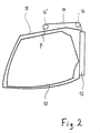
- Fig. 2
- eine aufgebrochene, schematische Seitenansicht des Gepäckfaches aus Fig. 1,
- Fig. 3
- eine auseinandergezogene, räumliche Darstellung des Gepäckfaches aus Fig. 1 ohne die Kraftübertragungseinrichtung in Gestalt des Seiles, und
- Fig. 4
- eine räumliche Ansicht des Gepäckfaches aus Fig. 1 von hinten, die die Integration der Kraftunterstützungseinrichtung in ein Gehäuse des Gepäckfaches zeigt.
- In Figur 1 ist ein allgemein mit 10 bezeichnetes absenkbares Überkopf-Gepäckfach eines nicht weiter dargestellten Flugzeuges gezeigt. Hinter der Rückseite des Gepäckfaches 10 ist eine als Kraftunterstützungsmodul 12 ausgeführte Kraftunterstützungseinrichtung montiert, die mittels eines als flexible Kraftübertragungseinrichtung dienenden Seils 14 eine Unterstützungskraft auf das Gepäckfach 10 überträgt, um die zum Öffnen und Schließen des Gepäckfaches 10 notwendige Kraft auf einem niedrigen Niveau zu halten, unabhängig davon, ob das Gepäckfach 12 leer oder voll beladen ist. Das Seil 14 ist mit seinem einen Ende im Kraftunterstützungsmodul 12 und mit seinem anderen Ende am Gepäckfach 10 befestigt und über zwei hier nur angedeutete Umlenkrollen 16, 16' geführt.
- Wie aus den Fig. 2 und 3 besser zu erkennen, ist das Gepäckfach 10 in einem Gehäuse 18 aufgenommen, welches auf nicht weiter dargestellte Weise an der tragenden Struktur des Flugzeuges befestigt ist. Das Gepäckfach 10 ist in dem Gehäuse 18 mittels zweier Führungseinrichtungen 20 und 20', die auf der einen bzw. der anderen Seite des Gepäckfaches 10 angeordnet sind und jeweils zwei Hebel 21, 22 bzw. 21', 22' aufweisen, derart geführt, dass es beim Öffnen aus dem Gehäuse 18 nach unten herausschwenkt und sich dabei gleichzeitig absenkt.
- Das Kraftunterstützungsmodul 12 ist, wie besonders aus den Fig. 3 und 4 zu erkennen, vollständig in eine Rückwand des Gehäuses 18 eingelassen. Im gezeigten Ausführungsbeispiel ist das Kraftunterstützungsmodul 12 etwa in der Mitte der Rückwand des Gehäuses 18 angeordnet.
- Das Kraftunterstützungsmodul 12 ist als separat handhabbare Einheit ausgebildet und weist selbst ein Gehäuse 24 auf, in dem alle zur Bereitstellung der gewünschten Unterstützungskraft notwendigen Bauteile untergebracht sind. Das Kraftunterstützungsmodul 12 ist dazu in der Lage, die bereitgestellte Unterstützungskraft dem Beladungszustand des Gepäckfaches 10 anzupassen, so dass ein Benutzer eine zumindest im wesentlichen immer gleiche, vom Beladungszustand unabhängige Schließkraft aufbringen muss, um das Gepäckfach 10 nach oben zu drücken und zu schließen.
- Bei dem dargestellten Ausführungsbeispiel tritt das die Unterstützungskraft auf das Gepäckfach 10 übertragende Seil 14 oben aus dem Kraftunterstützungsmodul 12 aus, wird dann mittels der ersten Umlenkrolle 16 so umgelenkt, dass es im wesentlichen parallel zur Oberseite des Gehäuses 18 verläuft, und wird dann von der zweiten Umlenkrolle 16' nach unten in Richtung auf die Oberseite 26 des Gepäckfaches 10 umgelenkt. An einem Kraftangriffspunkt P auf der Oberseite 26 des Gepäckfaches 10 ist das Seil 14 geeignet befestigt. In dem in Fig. 1 gezeigten Ausführungsbeispiel ist der Kraftangriffspunkt P in der Mitte zwischen den beiden Seiten des Gepäckfaches 10 und nahe einem vorderen Rand 28 der Oberseite 26 des Gepäckfaches 10 angeordnet. Abhängig von den Einbaubedingungen des Gepäckfaches 10 kann der Kraftangriffspunkt P jedoch auch vom vorderen Rand 28 entfernt angeordnet sein, beispielsweise etwa in der Mitte der Oberseite 26 des Gepäckfaches 10 wie in Fig. 2 dargestellt.
- Nicht gezeigte Ausführungsformen können mehrere Kraftangriffspunkte aufweisen und statt des Seils 14 können andere flexible Kraftübertragungseinrichtungen zum Einsatz kommen, beispielsweise Ketten oder Bowdenzüge.
Claims (9)
- Absenkbares Gepäckfach (10), insbesondere für ein Passagierflugzeug, mit einer Kraftunterstützungseinrichtung zur Bereitstellung einer Unterstützungskraft beim Öffnen und/oder Schließen des Gepäckfaches (10), wobei die von der Kraftunterstützungseinrichtung bereitgestellte Kraft mittels einer flexiblen Kraftübertragungseinrichtung auf das Gepäckfach (10) übertragen wird und die Kraftunterstützungseinrichtung die einzige auf das Gepäckfach (10) wirkende Kraftunterstützungseinrichtung ist, und wobei die von der Kraftunterstützungseinrichtung bereitgestellte Kraft mittels einer einzigen flexiblen Kraftübertragungseinrichtung auf das Gepäckfach (10) übertragen wird, dadurch gekennzeichnet, dass- die Kraftunterstützungseinrichtung hinter der Rückseite des Gepäckfaches angeordnet ist,- die Kraftunterstützungseinrichtung als Kraftunterstützungsmodul (12) mit einem eigenen Gehäuse (24) ausgeführt ist,- in dem Gehäuse (24) des Kraftunterstützungsmoduls (12) ein Federsystem die Unterstützungskraft erzeugt.
- Gepäckfach nach Anspruch 1,
dadurch gekennzeichnet, dass die Kraftunterstützungseinrichtung an einem Gehäuse (18) befestigt ist, in dem das Gepäckfach (10) geführt ist. - Gepäckfach nach Anspruch 1 oder 2,
dadurch gekennzeichnet, dass die flexible Kraftübertragungseinrichtung an oder nahe einer Oberseite (26) des Gepäckfaches (10) angreift. - Gepäckfach nach Anspruch 3,
dadurch gekennzeichnet, dass die flexible Kraftübertragungseinrichtung bezüglich der Breitenerstreckung des Gepäckfaches (10) zumindest näherungsweise in der Mitte angreift. - Gepäckfach nach Anspruch 4,
dadurch gekennzeichnet, dass die flexible Kraftübertragungseinrichtung an oder nahe einem vorderen Rand (28) der Oberseite (26) des Gepäckfaches (10) angreift. - Gepäckfach nach einem der vorhergehenden Ansprüche,
dadurch gekennzeichnet, dass die flexible Kraftübertragungseinrichtung ein über zumindest eine Umlenkrolle (16) geführtes Seil (14) ist. - Gepäckfach nach einem der Ansprüche 1 bis 5,
dadurch gekennzeichnet, dass die flexible Kraftübertragungseinrichtung eine wenigstens einmal umgelenkte Kette ist. - Gepäckfach nach einem der Ansprüche 1 bis 5,
dadurch gekennzeichnet, dass die flexible Kraftübertragungseinrichtung ein Bowdenzug ist. - Gepäckfach nach einem der vorhergehenden Ansprüche,
dadurch gekennzeichnet, dass die Unterstützungskraft sich in Abhängigkeit des Beladungsgewichtes des Gepäckfaches (10) ändert.
Applications Claiming Priority (3)
| Application Number | Priority Date | Filing Date | Title |
|---|---|---|---|
| DE10222124A DE10222124B4 (de) | 2002-05-17 | 2002-05-17 | Absenkbares Gepäckfach mit rückseitiger Kraftunterstützungseinrichtung |
| DE10222124 | 2002-05-17 | ||
| PCT/EP2003/005249 WO2003097455A1 (de) | 2002-05-17 | 2003-05-19 | Absenkbares gepäckfach mit rückseitiger kraftunterstützungseinrichtung |
Publications (2)
| Publication Number | Publication Date |
|---|---|
| EP1506116A1 EP1506116A1 (de) | 2005-02-16 |
| EP1506116B1 true EP1506116B1 (de) | 2006-06-28 |
Family
ID=29285544
Family Applications (1)
| Application Number | Title | Priority Date | Filing Date |
|---|---|---|---|
| EP03752767A Expired - Lifetime EP1506116B1 (de) | 2002-05-17 | 2003-05-19 | Absenkbares gepäckfach mit rückseitiger kraftunterstützungseinrichtung |
Country Status (8)
| Country | Link |
|---|---|
| US (1) | US7118068B2 (de) |
| EP (1) | EP1506116B1 (de) |
| AT (1) | ATE331661T1 (de) |
| CA (1) | CA2486155C (de) |
| DE (2) | DE10222124B4 (de) |
| ES (1) | ES2268410T3 (de) |
| RU (1) | RU2300485C2 (de) |
| WO (1) | WO2003097455A1 (de) |
Families Citing this family (22)
| Publication number | Priority date | Publication date | Assignee | Title |
|---|---|---|---|---|
| DE60200735T2 (de) * | 2001-05-24 | 2005-01-05 | Heath Tecna Inc., Bellingham | Entlastungsvorrichtung für eine obere Gepäckablage |
| AT413812B (de) * | 2001-10-17 | 2006-06-15 | Fischer Adv Components Gmbh | Aufhängevorrichtung für absenkbare gebäckablagebehälter |
| DE10222123A1 (de) * | 2002-05-17 | 2003-11-27 | Aircabin Gmbh | Absenkbares Gepäckfach mit Gasdruckfederverriegelung |
| USD562756S1 (en) * | 2002-07-26 | 2008-02-26 | The Boeing Company | Aircraft luggage bin |
| US8047468B2 (en) * | 2005-10-14 | 2011-11-01 | The Boeing Company | Stowage bin with shear fittings |
| US20070084966A1 (en) * | 2005-10-14 | 2007-04-19 | Haynes Michael S | Stowage bin with shear fittings |
| CA2658623C (en) * | 2006-07-24 | 2015-02-03 | Airbus | Baggage bin and associated door intended in particular for an aircraft |
| DE102006045189B4 (de) * | 2006-09-25 | 2008-11-27 | Airbus Deutschland Gmbh | Kraftunterstützungssystem |
| USD609160S1 (en) * | 2007-03-27 | 2010-02-02 | The Boeing Company | Bin storage compartment |
| USD608721S1 (en) * | 2007-03-27 | 2010-01-26 | The Boeing Company | Overhead stowage compartment |
| DE102009057014B4 (de) * | 2009-12-04 | 2012-05-03 | Diehl Aircabin Gmbh | Vorrichtung zum Schließen einer absenkbaren Schütte eines Gepäckfachs |
| WO2011139918A2 (en) * | 2010-05-03 | 2011-11-10 | Jonathan Roberts | System and method for an automatically adjusting force engine and assisted storage |
| US8770515B1 (en) | 2010-06-02 | 2014-07-08 | The Boeing Company | Movement assistance system for a storage bin |
| DE102011006461A1 (de) | 2011-03-30 | 2012-10-04 | Bombardier Transportation Gmbh | Klappe mit Fangsicherung |
| DE102011108895A1 (de) * | 2011-07-29 | 2013-01-31 | Airbus Operations Gmbh | Tragende Struktur für bewegliches Staufach |
| DE102011118553B4 (de) * | 2011-11-16 | 2019-07-11 | Diehl Aviation Laupheim Gmbh | Gepäckablagefach für ein Flugzeug und Flugzeug mit dem Gepäckablagefach |
| US8657231B2 (en) | 2012-03-07 | 2014-02-25 | Heath Tecna Inc. | Aircraft cabin bin retrofit |
| DE102012005918B4 (de) * | 2012-03-26 | 2019-03-21 | Diehl Aerospace Gmbh | Gepäckablagefach für ein Flugzeug sowie Flugzeug mit dem Gepäckablagefach |
| US20140260735A1 (en) * | 2013-03-15 | 2014-09-18 | Jonathan Roberts | Counterbalance system for assisting a user |
| US9980564B2 (en) * | 2013-03-15 | 2018-05-29 | Jonathan Roberts | System and method for assembling and using assisted storage |
| US9738386B2 (en) | 2015-04-09 | 2017-08-22 | The Boeing Company | Overhead stowage bin assembly for a vehicle |
| US9745064B2 (en) * | 2015-11-26 | 2017-08-29 | Goodrich Corporation | Aircraft overhead bin monitoring and alert system |
Family Cites Families (12)
| Publication number | Priority date | Publication date | Assignee | Title |
|---|---|---|---|---|
| US4076351A (en) * | 1976-04-19 | 1978-02-28 | Hobart Dale Wyant | Up-down cabinet |
| US5058846A (en) * | 1990-02-23 | 1991-10-22 | Hoyt-Close Products, Inc. | Pull down display and storage apparatus |
| DE4130644A1 (de) * | 1991-09-14 | 1993-03-18 | Airbus Gmbh | Ueberkopf-gepaeckablage mit einer absenkbaren schale, insbesondere fuer ein passagierflugzeug |
| DE4335151C2 (de) * | 1993-10-15 | 1996-09-26 | Daimler Benz Aerospace Airbus | Überkopf-Gepäckablage, insbesondere für ein Passagierflugzeug |
| US5456529A (en) * | 1993-12-30 | 1995-10-10 | The Boeing Company | Powered overhead stowage bin |
| DE4446772C1 (de) * | 1994-12-24 | 1996-05-15 | Daimler Benz Aerospace Airbus | Vorrichtung zum Führen einer absenkbaren Schale für eine Überkopf-Gepäckablage, insbesondere in einem Passagierflugzeug |
| DE19617657C2 (de) | 1996-05-03 | 2001-04-26 | Eads Airbus Gmbh | Vorrichtung zum Führen einer absenkbaren Schale für eine Überkopf-Gepäckablage, insbesondere in einem Passagierflugzeug |
| US5934615A (en) * | 1997-08-25 | 1999-08-10 | Hexcel Corporation | Luggage bins with articulating mechanism |
| DE19800588C2 (de) * | 1998-01-09 | 2002-04-11 | Airbus Gmbh | Vorrichtung zum Führen einer absenkbaren Schale für eine Gepäckablage, insbesondere in einem Passagierflugzeug |
| US6357842B1 (en) * | 1999-01-25 | 2002-03-19 | Bruce E. Nott | Overhead storage device |
| DE10001038B4 (de) * | 2000-01-13 | 2004-01-29 | Airbus Deutschland Gmbh | Gepäckablage mit einem absenkbaren Gepäckfach, insbesondere für eine Flugzeugpassagierkabine |
| US6691951B2 (en) * | 2001-10-26 | 2004-02-17 | Britax Heath Tecna Inc. | Variable load assist mechanism for an overhead bin |
-
2002
- 2002-05-17 DE DE10222124A patent/DE10222124B4/de not_active Expired - Fee Related
-
2003
- 2003-05-19 AT AT03752767T patent/ATE331661T1/de not_active IP Right Cessation
- 2003-05-19 US US10/514,405 patent/US7118068B2/en not_active Expired - Fee Related
- 2003-05-19 RU RU2004137106/11A patent/RU2300485C2/ru not_active IP Right Cessation
- 2003-05-19 DE DE50304064T patent/DE50304064D1/de not_active Expired - Lifetime
- 2003-05-19 WO PCT/EP2003/005249 patent/WO2003097455A1/de not_active Ceased
- 2003-05-19 EP EP03752767A patent/EP1506116B1/de not_active Expired - Lifetime
- 2003-05-19 CA CA002486155A patent/CA2486155C/en not_active Expired - Fee Related
- 2003-05-19 ES ES03752767T patent/ES2268410T3/es not_active Expired - Lifetime
Also Published As
| Publication number | Publication date |
|---|---|
| WO2003097455A1 (de) | 2003-11-27 |
| US20050224643A1 (en) | 2005-10-13 |
| DE10222124B4 (de) | 2005-02-10 |
| DE50304064D1 (de) | 2006-08-10 |
| RU2300485C2 (ru) | 2007-06-10 |
| DE10222124A1 (de) | 2003-11-27 |
| US7118068B2 (en) | 2006-10-10 |
| RU2004137106A (ru) | 2006-04-27 |
| ES2268410T3 (es) | 2007-03-16 |
| CA2486155C (en) | 2008-08-19 |
| EP1506116A1 (de) | 2005-02-16 |
| CA2486155A1 (en) | 2003-11-27 |
| ATE331661T1 (de) | 2006-07-15 |
Similar Documents
| Publication | Publication Date | Title |
|---|---|---|
| DE10222124B4 (de) | Absenkbares Gepäckfach mit rückseitiger Kraftunterstützungseinrichtung | |
| EP3482024B1 (de) | Griffvorrichtung mit einem flächenbündigen griff | |
| DE102020209607B4 (de) | Verschlussanordnung zum Verschließen einer Tankmulde einer Karosserie eines Kraftfahrzeugs | |
| DE2602092A1 (de) | Rollenblock mit seilklemmvorrichtung fuer grosschotbeschlaege auf segeljollen | |
| EP0259568A2 (de) | Schwenkschiebetür für Fahrzeuge | |
| EP1506115A1 (de) | Kraftunterstützungsmodul zur bereitstellung einer lastabhängigen unterstützungskraft | |
| DE102017109113A1 (de) | Fahrzeugtürgriff | |
| DE102008045178A1 (de) | Pedalanordnung mit einem um eine horizontale Achse schwenkbaren stehenden Pedal | |
| EP2094923A2 (de) | Verriegelungsvorrichtung für schiebetüren von luftfahrzeugen, insbesondere von hubschraubern | |
| DE2318774A1 (de) | Antrieb fuer eine fahrzeugtuer | |
| DE19617657A1 (de) | Vorrichtung zum Führen einer absenkbaren Schale für eine Überkopf-Gepäckablage, insbesondere in einem Passagierflugzeug | |
| DE1505721A1 (de) | Vorrichtung zur Verriegelung eines Kraftfahrzeug-Klappverdecks | |
| DE102017206309B4 (de) | Kraftfahrzeug mit einer Laderaumabdeckung | |
| DE102005061127B4 (de) | Luftfahrzeugtür-Anordnung sowie Luftfahrzeugrumpf mit einer derartigen Luftfahrzeugtür-Anordnung | |
| DE3048652C2 (de) | Handbetätigungsanordnung für Frachtladesysteme | |
| DE102021104519B4 (de) | Vorrichtung zum Öffnen und Verschließen einer Zugriffsöffnung in einer Fahrzeugkarosserie | |
| DE2632890C2 (de) | Ortsfeste Kupplungsvorrichtung einer Unterflurschleppkettenföderanlage | |
| EP3266964B1 (de) | Anordnung zur verhinderung eines selbsttätigen öffnens einer fahrzeugtür oder-klappe sowie fahrzeug mit einer derartigen anordnung | |
| DE10164345B4 (de) | Sicherheitsvorrichtung für Schiebetüren von Kraftfahrzeugen | |
| DE4446904C1 (de) | Kraftfahrzeug-Türgriff | |
| DE69605517T2 (de) | Trägerbalken für Anhänger | |
| WO2020003061A1 (de) | Kraftfahrzeugschliessmodul mit klappbarer lagerung | |
| DE3301973C2 (de) | Mastfußanordnung für ein Segelbrett | |
| DE8623831U1 (de) | Schwenkschiebetür für Fahrzeuge, insbesondere für Personenbeförderungswagen | |
| DE102016219300B4 (de) | Türantrieb für eine Kraftwagentür |
Legal Events
| Date | Code | Title | Description |
|---|---|---|---|
| PUAI | Public reference made under article 153(3) epc to a published international application that has entered the european phase |
Free format text: ORIGINAL CODE: 0009012 |
|
| 17P | Request for examination filed |
Effective date: 20040930 |
|
| AK | Designated contracting states |
Kind code of ref document: A1 Designated state(s): AT BE BG CH CY CZ DE DK EE ES FI FR GB GR HU IE IT LI LU MC NL PT RO SE SI SK TR |
|
| GRAP | Despatch of communication of intention to grant a patent |
Free format text: ORIGINAL CODE: EPIDOSNIGR1 |
|
| RAP1 | Party data changed (applicant data changed or rights of an application transferred) |
Owner name: AIRBUS DEUTSCHLAND GMBH |
|
| GRAS | Grant fee paid |
Free format text: ORIGINAL CODE: EPIDOSNIGR3 |
|
| GRAA | (expected) grant |
Free format text: ORIGINAL CODE: 0009210 |
|
| AK | Designated contracting states |
Kind code of ref document: B1 Designated state(s): AT BE BG CH CY CZ DE DK EE ES FI FR GB GR HU IE IT LI LU MC NL PT RO SE SI SK TR |
|
| PG25 | Lapsed in a contracting state [announced via postgrant information from national office to epo] |
Ref country code: IT Free format text: LAPSE BECAUSE OF FAILURE TO SUBMIT A TRANSLATION OF THE DESCRIPTION OR TO PAY THE FEE WITHIN THE PRESCRIBED TIME-LIMIT;WARNING: LAPSES OF ITALIAN PATENTS WITH EFFECTIVE DATE BEFORE 2007 MAY HAVE OCCURRED AT ANY TIME BEFORE 2007. THE CORRECT EFFECTIVE DATE MAY BE DIFFERENT FROM THE ONE RECORDED. Effective date: 20060628 Ref country code: FI Free format text: LAPSE BECAUSE OF FAILURE TO SUBMIT A TRANSLATION OF THE DESCRIPTION OR TO PAY THE FEE WITHIN THE PRESCRIBED TIME-LIMIT Effective date: 20060628 Ref country code: RO Free format text: LAPSE BECAUSE OF FAILURE TO SUBMIT A TRANSLATION OF THE DESCRIPTION OR TO PAY THE FEE WITHIN THE PRESCRIBED TIME-LIMIT Effective date: 20060628 Ref country code: IE Free format text: LAPSE BECAUSE OF FAILURE TO SUBMIT A TRANSLATION OF THE DESCRIPTION OR TO PAY THE FEE WITHIN THE PRESCRIBED TIME-LIMIT Effective date: 20060628 Ref country code: NL Free format text: LAPSE BECAUSE OF FAILURE TO SUBMIT A TRANSLATION OF THE DESCRIPTION OR TO PAY THE FEE WITHIN THE PRESCRIBED TIME-LIMIT Effective date: 20060628 Ref country code: SI Free format text: LAPSE BECAUSE OF FAILURE TO SUBMIT A TRANSLATION OF THE DESCRIPTION OR TO PAY THE FEE WITHIN THE PRESCRIBED TIME-LIMIT Effective date: 20060628 Ref country code: CZ Free format text: LAPSE BECAUSE OF FAILURE TO SUBMIT A TRANSLATION OF THE DESCRIPTION OR TO PAY THE FEE WITHIN THE PRESCRIBED TIME-LIMIT Effective date: 20060628 Ref country code: SK Free format text: LAPSE BECAUSE OF FAILURE TO SUBMIT A TRANSLATION OF THE DESCRIPTION OR TO PAY THE FEE WITHIN THE PRESCRIBED TIME-LIMIT Effective date: 20060628 |
|
| REG | Reference to a national code |
Ref country code: GB Ref legal event code: FG4D Free format text: NOT ENGLISH |
|
| REG | Reference to a national code |
Ref country code: CH Ref legal event code: EP |
|
| REG | Reference to a national code |
Ref country code: IE Ref legal event code: FG4D Free format text: LANGUAGE OF EP DOCUMENT: GERMAN |
|
| REF | Corresponds to: |
Ref document number: 50304064 Country of ref document: DE Date of ref document: 20060810 Kind code of ref document: P |
|
| GBT | Gb: translation of ep patent filed (gb section 77(6)(a)/1977) |
Effective date: 20060904 |
|
| PG25 | Lapsed in a contracting state [announced via postgrant information from national office to epo] |
Ref country code: DK Free format text: LAPSE BECAUSE OF FAILURE TO SUBMIT A TRANSLATION OF THE DESCRIPTION OR TO PAY THE FEE WITHIN THE PRESCRIBED TIME-LIMIT Effective date: 20060928 |
|
| REG | Reference to a national code |
Ref country code: SE Ref legal event code: TRGR |
|
| PG25 | Lapsed in a contracting state [announced via postgrant information from national office to epo] |
Ref country code: PT Free format text: LAPSE BECAUSE OF FAILURE TO SUBMIT A TRANSLATION OF THE DESCRIPTION OR TO PAY THE FEE WITHIN THE PRESCRIBED TIME-LIMIT Effective date: 20061128 |
|
| NLV1 | Nl: lapsed or annulled due to failure to fulfill the requirements of art. 29p and 29m of the patents act | ||
| ET | Fr: translation filed | ||
| REG | Reference to a national code |
Ref country code: IE Ref legal event code: FD4D |
|
| REG | Reference to a national code |
Ref country code: ES Ref legal event code: FG2A Ref document number: 2268410 Country of ref document: ES Kind code of ref document: T3 |
|
| PLBE | No opposition filed within time limit |
Free format text: ORIGINAL CODE: 0009261 |
|
| STAA | Information on the status of an ep patent application or granted ep patent |
Free format text: STATUS: NO OPPOSITION FILED WITHIN TIME LIMIT |
|
| 26N | No opposition filed |
Effective date: 20070329 |
|
| BERE | Be: lapsed |
Owner name: AIRBUS DEUTSCHLAND G.M.B.H. Effective date: 20070531 |
|
| REG | Reference to a national code |
Ref country code: CH Ref legal event code: PL |
|
| PG25 | Lapsed in a contracting state [announced via postgrant information from national office to epo] |
Ref country code: MC Free format text: LAPSE BECAUSE OF NON-PAYMENT OF DUE FEES Effective date: 20070531 |
|
| PG25 | Lapsed in a contracting state [announced via postgrant information from national office to epo] |
Ref country code: CH Free format text: LAPSE BECAUSE OF NON-PAYMENT OF DUE FEES Effective date: 20070531 Ref country code: LI Free format text: LAPSE BECAUSE OF NON-PAYMENT OF DUE FEES Effective date: 20070531 |
|
| PG25 | Lapsed in a contracting state [announced via postgrant information from national office to epo] |
Ref country code: BE Free format text: LAPSE BECAUSE OF NON-PAYMENT OF DUE FEES Effective date: 20070531 |
|
| PG25 | Lapsed in a contracting state [announced via postgrant information from national office to epo] |
Ref country code: GR Free format text: LAPSE BECAUSE OF FAILURE TO SUBMIT A TRANSLATION OF THE DESCRIPTION OR TO PAY THE FEE WITHIN THE PRESCRIBED TIME-LIMIT Effective date: 20060929 |
|
| PG25 | Lapsed in a contracting state [announced via postgrant information from national office to epo] |
Ref country code: BG Free format text: LAPSE BECAUSE OF FAILURE TO SUBMIT A TRANSLATION OF THE DESCRIPTION OR TO PAY THE FEE WITHIN THE PRESCRIBED TIME-LIMIT Effective date: 20060928 |
|
| PG25 | Lapsed in a contracting state [announced via postgrant information from national office to epo] |
Ref country code: EE Free format text: LAPSE BECAUSE OF FAILURE TO SUBMIT A TRANSLATION OF THE DESCRIPTION OR TO PAY THE FEE WITHIN THE PRESCRIBED TIME-LIMIT Effective date: 20060628 |
|
| PG25 | Lapsed in a contracting state [announced via postgrant information from national office to epo] |
Ref country code: AT Free format text: LAPSE BECAUSE OF NON-PAYMENT OF DUE FEES Effective date: 20070519 |
|
| PG25 | Lapsed in a contracting state [announced via postgrant information from national office to epo] |
Ref country code: LU Free format text: LAPSE BECAUSE OF NON-PAYMENT OF DUE FEES Effective date: 20070519 Ref country code: CY Free format text: LAPSE BECAUSE OF FAILURE TO SUBMIT A TRANSLATION OF THE DESCRIPTION OR TO PAY THE FEE WITHIN THE PRESCRIBED TIME-LIMIT Effective date: 20060628 |
|
| PG25 | Lapsed in a contracting state [announced via postgrant information from national office to epo] |
Ref country code: TR Free format text: LAPSE BECAUSE OF FAILURE TO SUBMIT A TRANSLATION OF THE DESCRIPTION OR TO PAY THE FEE WITHIN THE PRESCRIBED TIME-LIMIT Effective date: 20060628 Ref country code: HU Free format text: LAPSE BECAUSE OF FAILURE TO SUBMIT A TRANSLATION OF THE DESCRIPTION OR TO PAY THE FEE WITHIN THE PRESCRIBED TIME-LIMIT Effective date: 20061229 |
|
| REG | Reference to a national code |
Ref country code: FR Ref legal event code: PLFP Year of fee payment: 14 |
|
| PGFP | Annual fee paid to national office [announced via postgrant information from national office to epo] |
Ref country code: GB Payment date: 20160520 Year of fee payment: 14 Ref country code: ES Payment date: 20160512 Year of fee payment: 14 Ref country code: DE Payment date: 20160520 Year of fee payment: 14 |
|
| PGFP | Annual fee paid to national office [announced via postgrant information from national office to epo] |
Ref country code: FR Payment date: 20160520 Year of fee payment: 14 Ref country code: SE Payment date: 20160519 Year of fee payment: 14 Ref country code: IT Payment date: 20160524 Year of fee payment: 14 |
|
| REG | Reference to a national code |
Ref country code: DE Ref legal event code: R119 Ref document number: 50304064 Country of ref document: DE |
|
| REG | Reference to a national code |
Ref country code: SE Ref legal event code: EUG |
|
| GBPC | Gb: european patent ceased through non-payment of renewal fee |
Effective date: 20170519 |
|
| PG25 | Lapsed in a contracting state [announced via postgrant information from national office to epo] |
Ref country code: SE Free format text: LAPSE BECAUSE OF NON-PAYMENT OF DUE FEES Effective date: 20170520 |
|
| REG | Reference to a national code |
Ref country code: FR Ref legal event code: ST Effective date: 20180131 |
|
| PG25 | Lapsed in a contracting state [announced via postgrant information from national office to epo] |
Ref country code: DE Free format text: LAPSE BECAUSE OF NON-PAYMENT OF DUE FEES Effective date: 20171201 Ref country code: GB Free format text: LAPSE BECAUSE OF NON-PAYMENT OF DUE FEES Effective date: 20170519 |
|
| PG25 | Lapsed in a contracting state [announced via postgrant information from national office to epo] |
Ref country code: IT Free format text: LAPSE BECAUSE OF NON-PAYMENT OF DUE FEES Effective date: 20170519 Ref country code: FR Free format text: LAPSE BECAUSE OF NON-PAYMENT OF DUE FEES Effective date: 20170531 |
|
| REG | Reference to a national code |
Ref country code: ES Ref legal event code: FD2A Effective date: 20180705 |
|
| PG25 | Lapsed in a contracting state [announced via postgrant information from national office to epo] |
Ref country code: ES Free format text: LAPSE BECAUSE OF NON-PAYMENT OF DUE FEES Effective date: 20170520 |