EP1501766B1 - Glasschneideverfahren ohne brechen - Google Patents
Glasschneideverfahren ohne brechen Download PDFInfo
- Publication number
- EP1501766B1 EP1501766B1 EP03749931A EP03749931A EP1501766B1 EP 1501766 B1 EP1501766 B1 EP 1501766B1 EP 03749931 A EP03749931 A EP 03749931A EP 03749931 A EP03749931 A EP 03749931A EP 1501766 B1 EP1501766 B1 EP 1501766B1
- Authority
- EP
- European Patent Office
- Prior art keywords
- glazing
- glazing unit
- glass
- thickness
- sub
- Prior art date
- Legal status (The legal status is an assumption and is not a legal conclusion. Google has not performed a legal analysis and makes no representation as to the accuracy of the status listed.)
- Expired - Lifetime
Links
- 239000011521 glass Substances 0.000 title claims abstract description 125
- 238000005520 cutting process Methods 0.000 title claims abstract description 57
- 238000000034 method Methods 0.000 title claims abstract description 40
- 238000011282 treatment Methods 0.000 claims abstract description 33
- 230000006835 compression Effects 0.000 claims abstract description 31
- 238000007906 compression Methods 0.000 claims abstract description 31
- 238000009826 distribution Methods 0.000 claims abstract description 8
- 239000000126 substance Substances 0.000 claims description 45
- 238000005452 bending Methods 0.000 claims description 13
- 229920000642 polymer Polymers 0.000 claims description 8
- 229910001414 potassium ion Inorganic materials 0.000 claims description 5
- 229910001415 sodium ion Inorganic materials 0.000 claims description 4
- 230000003247 decreasing effect Effects 0.000 claims description 3
- 230000008021 deposition Effects 0.000 claims description 3
- 239000011229 interlayer Substances 0.000 claims description 3
- 229910000272 alkali metal oxide Inorganic materials 0.000 claims description 2
- 229910001413 alkali metal ion Inorganic materials 0.000 claims 2
- 238000010791 quenching Methods 0.000 description 49
- 230000000171 quenching effect Effects 0.000 description 46
- 239000010410 layer Substances 0.000 description 34
- 239000007787 solid Substances 0.000 description 16
- 150000002500 ions Chemical class 0.000 description 14
- 241001639412 Verres Species 0.000 description 13
- XLYOFNOQVPJJNP-UHFFFAOYSA-N water Substances O XLYOFNOQVPJJNP-UHFFFAOYSA-N 0.000 description 10
- 229910003460 diamond Inorganic materials 0.000 description 6
- 239000010432 diamond Substances 0.000 description 6
- 239000000203 mixture Substances 0.000 description 6
- FGIUAXJPYTZDNR-UHFFFAOYSA-N potassium nitrate Chemical compound [K+].[O-][N+]([O-])=O FGIUAXJPYTZDNR-UHFFFAOYSA-N 0.000 description 6
- 238000005342 ion exchange Methods 0.000 description 5
- 238000004519 manufacturing process Methods 0.000 description 5
- 238000000605 extraction Methods 0.000 description 4
- 125000006850 spacer group Chemical group 0.000 description 4
- 238000005496 tempering Methods 0.000 description 4
- 229910018068 Li 2 O Inorganic materials 0.000 description 3
- XUIMIQQOPSSXEZ-UHFFFAOYSA-N Silicon Chemical compound [Si] XUIMIQQOPSSXEZ-UHFFFAOYSA-N 0.000 description 3
- RTAQQCXQSZGOHL-UHFFFAOYSA-N Titanium Chemical compound [Ti] RTAQQCXQSZGOHL-UHFFFAOYSA-N 0.000 description 3
- 230000015572 biosynthetic process Effects 0.000 description 3
- 210000004027 cell Anatomy 0.000 description 3
- 230000000694 effects Effects 0.000 description 3
- 230000000977 initiatory effect Effects 0.000 description 3
- 229920002037 poly(vinyl butyral) polymer Polymers 0.000 description 3
- 235000010333 potassium nitrate Nutrition 0.000 description 3
- 239000004323 potassium nitrate Substances 0.000 description 3
- 229910052710 silicon Inorganic materials 0.000 description 3
- 239000010703 silicon Substances 0.000 description 3
- 239000000758 substrate Substances 0.000 description 3
- 229910052719 titanium Inorganic materials 0.000 description 3
- 239000010936 titanium Substances 0.000 description 3
- 239000005341 toughened glass Substances 0.000 description 3
- NPYPAHLBTDXSSS-UHFFFAOYSA-N Potassium ion Chemical group [K+] NPYPAHLBTDXSSS-UHFFFAOYSA-N 0.000 description 2
- 229920000297 Rayon Polymers 0.000 description 2
- 229910052581 Si3N4 Inorganic materials 0.000 description 2
- 230000000052 comparative effect Effects 0.000 description 2
- 238000001816 cooling Methods 0.000 description 2
- 239000010730 cutting oil Substances 0.000 description 2
- 230000007423 decrease Effects 0.000 description 2
- 238000000151 deposition Methods 0.000 description 2
- 238000005304 joining Methods 0.000 description 2
- 239000004973 liquid crystal related substance Substances 0.000 description 2
- 239000002964 rayon Substances 0.000 description 2
- 238000009666 routine test Methods 0.000 description 2
- 150000003839 salts Chemical class 0.000 description 2
- KKNIUBFRGPFELP-UHFFFAOYSA-N secretolin Chemical compound N=1C=CNC=1CC(N)C(=O)NC(CO)C(=O)NC(CC(O)=O)C(=O)NCC(=O)NC(C(C)O)C(=O)NC(C(=O)NC(C(=O)NC(CO)C(=O)NC(CCC(O)=O)C(=O)NC(CC(C)C)C(=O)NC(CO)C(=O)NC(CCCNC(N)=N)C(=O)NC(CC(C)C)C(=O)NC(CCCNC(N)=N)C(=O)NC(CC(O)=O)C(=O)NC(CO)C(=O)NC(C)C(=O)NC(CCCNC(N)=N)C(=O)NC(CC(C)C)C(=O)NC(CCC(N)=O)C(=O)NC(CCCNC(N)=N)C(=O)NC(CC(C)C)C(=O)NC(CC(C)C)C(=O)NC(CCC(N)=O)C(=O)NCC(=O)NC(CC(C)C)C(=O)NC(C(C)C)C(O)=O)C(C)O)CC1=CC=CC=C1 KKNIUBFRGPFELP-UHFFFAOYSA-N 0.000 description 2
- HQVNEWCFYHHQES-UHFFFAOYSA-N silicon nitride Chemical group N12[Si]34N5[Si]62N3[Si]51N64 HQVNEWCFYHHQES-UHFFFAOYSA-N 0.000 description 2
- FUJCRWPEOMXPAD-UHFFFAOYSA-N Li2O Inorganic materials [Li+].[Li+].[O-2] FUJCRWPEOMXPAD-UHFFFAOYSA-N 0.000 description 1
- KKCBUQHMOMHUOY-UHFFFAOYSA-N Na2O Inorganic materials [O-2].[Na+].[Na+] KKCBUQHMOMHUOY-UHFFFAOYSA-N 0.000 description 1
- 241001080024 Telles Species 0.000 description 1
- GWEVSGVZZGPLCZ-UHFFFAOYSA-N Titan oxide Chemical compound O=[Ti]=O GWEVSGVZZGPLCZ-UHFFFAOYSA-N 0.000 description 1
- NRTOMJZYCJJWKI-UHFFFAOYSA-N Titanium nitride Chemical compound [Ti]#N NRTOMJZYCJJWKI-UHFFFAOYSA-N 0.000 description 1
- 240000008042 Zea mays Species 0.000 description 1
- 238000005299 abrasion Methods 0.000 description 1
- 239000003513 alkali Substances 0.000 description 1
- 230000003416 augmentation Effects 0.000 description 1
- 238000010924 continuous production Methods 0.000 description 1
- 210000002858 crystal cell Anatomy 0.000 description 1
- XUCJHNOBJLKZNU-UHFFFAOYSA-M dilithium;hydroxide Chemical compound [Li+].[Li+].[OH-] XUCJHNOBJLKZNU-UHFFFAOYSA-M 0.000 description 1
- 230000005669 field effect Effects 0.000 description 1
- 239000005357 flat glass Substances 0.000 description 1
- 239000005329 float glass Substances 0.000 description 1
- 230000014509 gene expression Effects 0.000 description 1
- 238000010438 heat treatment Methods 0.000 description 1
- 229910001416 lithium ion Inorganic materials 0.000 description 1
- 238000001755 magnetron sputter deposition Methods 0.000 description 1
- 239000011159 matrix material Substances 0.000 description 1
- 230000004048 modification Effects 0.000 description 1
- 238000012986 modification Methods 0.000 description 1
- 239000003921 oil Substances 0.000 description 1
- 230000000149 penetrating effect Effects 0.000 description 1
- 230000002093 peripheral effect Effects 0.000 description 1
- 238000005268 plasma chemical vapour deposition Methods 0.000 description 1
- 238000005498 polishing Methods 0.000 description 1
- 230000001681 protective effect Effects 0.000 description 1
- 238000007650 screen-printing Methods 0.000 description 1
- HBMJWWWQQXIZIP-UHFFFAOYSA-N silicon carbide Chemical compound [Si+]#[C-] HBMJWWWQQXIZIP-UHFFFAOYSA-N 0.000 description 1
- 229910010271 silicon carbide Inorganic materials 0.000 description 1
- 238000002791 soaking Methods 0.000 description 1
- 239000005361 soda-lime glass Substances 0.000 description 1
- HUAUNKAZQWMVFY-UHFFFAOYSA-M sodium;oxocalcium;hydroxide Chemical compound [OH-].[Na+].[Ca]=O HUAUNKAZQWMVFY-UHFFFAOYSA-M 0.000 description 1
- 238000009987 spinning Methods 0.000 description 1
- 238000004544 sputter deposition Methods 0.000 description 1
- 238000005728 strengthening Methods 0.000 description 1
- OGIDPMRJRNCKJF-UHFFFAOYSA-N titanium oxide Inorganic materials [Ti]=O OGIDPMRJRNCKJF-UHFFFAOYSA-N 0.000 description 1
- MTPVUVINMAGMJL-UHFFFAOYSA-N trimethyl(1,1,2,2,2-pentafluoroethyl)silane Chemical compound C[Si](C)(C)C(F)(F)C(F)(F)F MTPVUVINMAGMJL-UHFFFAOYSA-N 0.000 description 1
- 230000004584 weight gain Effects 0.000 description 1
- 235000019786 weight gain Nutrition 0.000 description 1
Images



Classifications
-
- C—CHEMISTRY; METALLURGY
- C03—GLASS; MINERAL OR SLAG WOOL
- C03B—MANUFACTURE, SHAPING, OR SUPPLEMENTARY PROCESSES
- C03B33/00—Severing cooled glass
- C03B33/02—Cutting or splitting sheet glass or ribbons; Apparatus or machines therefor
- C03B33/023—Cutting or splitting sheet glass or ribbons; Apparatus or machines therefor the sheet or ribbon being in a horizontal position
-
- C—CHEMISTRY; METALLURGY
- C03—GLASS; MINERAL OR SLAG WOOL
- C03B—MANUFACTURE, SHAPING, OR SUPPLEMENTARY PROCESSES
- C03B27/00—Tempering or quenching glass products
-
- C—CHEMISTRY; METALLURGY
- C03—GLASS; MINERAL OR SLAG WOOL
- C03B—MANUFACTURE, SHAPING, OR SUPPLEMENTARY PROCESSES
- C03B33/00—Severing cooled glass
- C03B33/02—Cutting or splitting sheet glass or ribbons; Apparatus or machines therefor
- C03B33/023—Cutting or splitting sheet glass or ribbons; Apparatus or machines therefor the sheet or ribbon being in a horizontal position
- C03B33/033—Apparatus for opening score lines in glass sheets
-
- C—CHEMISTRY; METALLURGY
- C03—GLASS; MINERAL OR SLAG WOOL
- C03C—CHEMICAL COMPOSITION OF GLASSES, GLAZES OR VITREOUS ENAMELS; SURFACE TREATMENT OF GLASS; SURFACE TREATMENT OF FIBRES OR FILAMENTS MADE FROM GLASS, MINERALS OR SLAGS; JOINING GLASS TO GLASS OR OTHER MATERIALS
- C03C21/00—Treatment of glass, not in the form of fibres or filaments, by diffusing ions or metals in the surface
- C03C21/001—Treatment of glass, not in the form of fibres or filaments, by diffusing ions or metals in the surface in liquid phase, e.g. molten salts, solutions
- C03C21/002—Treatment of glass, not in the form of fibres or filaments, by diffusing ions or metals in the surface in liquid phase, e.g. molten salts, solutions to perform ion-exchange between alkali ions
-
- Y—GENERAL TAGGING OF NEW TECHNOLOGICAL DEVELOPMENTS; GENERAL TAGGING OF CROSS-SECTIONAL TECHNOLOGIES SPANNING OVER SEVERAL SECTIONS OF THE IPC; TECHNICAL SUBJECTS COVERED BY FORMER USPC CROSS-REFERENCE ART COLLECTIONS [XRACs] AND DIGESTS
- Y10—TECHNICAL SUBJECTS COVERED BY FORMER USPC
- Y10T—TECHNICAL SUBJECTS COVERED BY FORMER US CLASSIFICATION
- Y10T428/00—Stock material or miscellaneous articles
- Y10T428/15—Sheet, web, or layer weakened to permit separation through thickness
-
- Y—GENERAL TAGGING OF NEW TECHNOLOGICAL DEVELOPMENTS; GENERAL TAGGING OF CROSS-SECTIONAL TECHNOLOGIES SPANNING OVER SEVERAL SECTIONS OF THE IPC; TECHNICAL SUBJECTS COVERED BY FORMER USPC CROSS-REFERENCE ART COLLECTIONS [XRACs] AND DIGESTS
- Y10—TECHNICAL SUBJECTS COVERED BY FORMER USPC
- Y10T—TECHNICAL SUBJECTS COVERED BY FORMER US CLASSIFICATION
- Y10T428/00—Stock material or miscellaneous articles
- Y10T428/24—Structurally defined web or sheet [e.g., overall dimension, etc.]
- Y10T428/24777—Edge feature
Definitions
- the invention relates to a method of cutting a glazing without the need to apply a breaking force.
- a chemical quenching can be performed on the cut glass, generally by immersing it in a bath of molten potassium nitrate.
- the chemically toughened glasses therefore have their definitive shape before the chemical quenching and they are not intended to be cut after completion of the quenching.
- the WO9846537 teaches particular compositions of glass obtained by chemical quenching (potassium ion exchange) for the production of glazing in the aeronautical field. No cutting is envisaged after chemical quenching.
- the EP793132 teaches cells consisting of a pair of glass slides having electrodes on their surface and at least one of which has undergone chemical quenching.
- the glass intended to be integrated in such a cell is chemically quenched and then cut and broken into as many individual elements that will be integrated into the cell.
- the chemical quenching is here carried out on a thickness of 20 ⁇ m at most.
- This document teaches that, after notching a glass, it is necessary to apply a pressure to break it, and that in the case of a chemically toughened glass, if the chemically treated layer is too thick, the break can be made extremely difficult.
- the object of EP793132 is to achieve a chemical quenching to break the glass in a conventional manner. To do this, glass having a maximum thickness of 2 mm is chemically treated to a maximum thickness of 20 microns.
- the EP875490 discloses a continuous process for preparing hardened glass by chemical quenching.
- the glass must have a maximum thickness of 1.2 mm and is quenched in less than two hours. Chemical quenching is carried out to a maximum thickness of 30 ⁇ m.
- the glass can be rolled up.
- the glass can be coated with layers, for example metallic and made by sputtering, and can find an application in LCD or DTR.
- the chemically treated glass can be cut into sheets or sheets. This document does not teach the particular conditions for cutting the glass without breaking.
- the EP982121 describes three-layer structures, at least one of which is made of glass and comprises notches.
- the notches may have zero width.
- the layer just below the nicked glass is flexible (p; e; it is a polymer).
- the notched glass may have been chemically hardened. If the notch has a non-zero width, it can be filled with a polymer having a refractive index identical to that of the notched glass.
- the applications envisaged are: security card, glazing of buildings, smart cards, photomasks.
- the cuts can be left visible to have a mirror effect.
- the EP964112 teaches a panel comprising a glass sheet having on one part of its thickness grooves horizontally arranged and parallel to each other. These cuts are preferably made by laser. This document does not envisage the chemical quenching of glass.
- the FR 1598242 , FR 2053664 and FR 2063482 teach thermal tempering in the presence of screens protecting certain areas of the quench. The cutting is then performed in these areas. This treatment necessarily generates an imbalance of the stresses in the thickness in comparison with a glass tempered glass without screen. Thus, these windows are not self-balancing in the thickness.
- a ribbon thus treated is not homogeneous and requires cutting in areas protected by screens.
- These documents do not teach how to make a glazing that can be cut without breaking after tracing at any location on its surface, while it is the case for glazing according to the invention because of their homogeneity .
- the screens recommended by these documents deteriorate the effect of thermal tempering at the edge, precisely where we expect usually strengthening by quenching.
- glazing has a very general meaning without limitation of form, encompassing all objects based on glass and generally comprising two generally parallel main faces, and in particular the frames of the figure 8 .
- the sub-crack propagates itself in a crack through the thickness of the glass, even in the absence of breaking force.
- the subcrack should reach the extended area of the glazing and be deeper than 10 ⁇ m.
- the invention makes it possible in particular to cut without breaking glass sheets of any thickness, in particular less than 500 ⁇ m, but also greater than 1.2 mm and even greater than 2.6 mm, thicknesses that are not usually known to be cut out. directly to the laser in the case of a glazing not in accordance with the invention.
- the cutting according to the invention leads more generally to a non-cutting slice for the hand, which is advantageous in terms of safety.
- the cut without breaking according to the invention is carried out on glass of thickness less than or equal to 5.2 mm.
- the first two treatments mentioned above intrinsically lead to a substantially isotropic biaxial stress distribution. These first two treatments also lead to constraints that are residual after cutting.
- the third treatment (submission to biaxial flexion) does not lead to residual stresses after cutting, since the bending forces disappear as soon as the glass breaks.
- the treatment imparts to the glass a substantially isotropic biaxial stress distribution, which means that the stresses are exerted in directions parallel to the glazing, and for a given depth, with substantially the same intensity in all directions parallel to the glazing.
- These biaxial stresses are generally isotropic in a plane parallel to the glazing.
- the invention allows the realization of a cutable glazing according to the invention anywhere.
- Such glazing may have a large surface area, especially greater than 10 cm, or even greater than 20 cm, or even greater than 50 cm, or even greater than 1 m, in all directions parallel to its main faces (in the case of flat glazing) .
- the glass Before said treatment, the glass may have no internal stress. It may in particular be a float glass, the glass may be of any composition, and in particular be of soda-lime type or may have one of the compositions described in the FR97 / 04508 or WO96 / 11887 .
- the glass must contain an alkaline oxide.
- This oxide may be Na 2 O or Li 2 O, and may be present in the glass for example from 1 to 20% by weight.
- the chemical quenching treatment consists of replacing alkaline ions initially in the glass with other larger alkaline ions. If the initial oxide is Na 2 O, chemical quenching is applied by KNO 3 treatment, so as to at least partially replace Na + ions with K + ions. If the initial oxide is Li 2 O, chemical quenching is applied by treatment with NaNO 3 or KNO 3 , so as to at least partially replace Li + ions as appropriate by Na + ions where K + .
- the cut glass according to the invention has improved edge mechanical strength.
- the quenching can therefore lead to a concentration gradient of K + or Na + ions perpendicular to at least one of the main faces and decreasing from said main face.
- the biasograph technique can be used. This technique is well known to those skilled in the art, and one can in particular refer to the work "Photoelasticity of glass", H. Aben, Guillemet C., Springer-Verlag 1993, page 150 .
- the biasograph technique gives a stress intensity profile such as the curve (1) represented on the figure 1 which represents the evolution of the sigma stress as a function of the depth in the glass (the x-axis is perpendicular to the glazing).
- the whole of the stresses ⁇ i corresponding to a thickness dz i is then measured for the whole curve (1), the value of dz i being, for example, 8 ⁇ m.
- the biasograph technique requires access to the edge of the glazing. To use this technique, it is preferable that the width of the glazing is equal to at least five times its thickness. Other methods of photoelasticity can also be used, such as the strayer refractometer.
- the chemical quenching is carried out by immersing the glazing to be treated in a hot bath of the chosen salt (generally NaNO 3 or KNO 3 ). This bath contains the concentrated salt.
- the chemical quenching is generally carried out between 380 ° C. and 520 ° C., and in any case at a temperature below the softening temperature of the glass to be treated.
- Chemical quenching produces an ion exchange on the surface of the treated glass to a depth of, for example, up to 50 ⁇ m.
- This ion exchange is at the origin of alkaline ion concentration gradients.
- this gradient is characterized by a decrease in the concentration of ions provided by the chemical quenching (usually K + or Na + ) from the main face and towards the core of the glazing.
- This gradient exists between the surface and for example a depth of at most 50 microns.
- This gradient is represented on the figure 2 by points whose density decreases the more one goes towards the interior of the glazing. The depth of the gradient is exaggerated in the figures to facilitate understanding.
- the glazing of the prior art chemically quenched, considering that they are not cut after chemical quenching, have the same composition over their entire surface, including the wafer.
- the figure 2 a) represents in section the edge of a chemically treated glazing after cutting. The cut gave birth to the slice (2).
- the trace of the sub-crack (3) is visible on the edge and is represented on the figure 2 a) by a bolder line (remember that a sub-crack is always visible on the cut edge of a glazing, to the naked eye if the glazing is of sufficient thickness, or under the microscope for glasses too thin, for example less than 500 ⁇ m thick).
- the chemical quenching of the glazing after cutting resulted in an exchange of alkaline ions between the glazing and the quenching medium.
- This exchange has created a gradient of concentration of alkali ions from the glazing surface towards the inside of the glazing, this gradient existing from the main parallel faces ((4) and (5) on the figure 2 ) of the glazing and at a sufficient distance from the slices (including that noted (2)), for example from the point (6) on the surface of a main face and perpendicular to this face towards the heart of the glazing.
- This point (6) can generally be at least 1 mm from the wafer.
- This gradient does not exist on the wafer in a direction perpendicular to the main faces but exists on the wafer in a direction parallel to the main faces of the glazing and at a sufficient distance from said main faces.
- the Figure 2 (b) represents a glazing unit according to the invention, for which the cutting has been performed after the chemical quenching treatment.
- the wafer (2) cut according to the invention has a variable composition according to which is close or remote from the main parallel faces of the glazing.
- the surface of the cut wafer according to the invention has a surface concentration gradient of alkaline ions between the main face having under-cracked and the core of the glazing. This is a fundamental difference with a cut glass before being treated by chemical quenching (case of the figure 2 a) ) for which this gradient on the slice does not exist.
- the slice cut according to the invention has this gradient and has the mark of the sub-crack, the latter may however subsequently be removed for example by abrasion or polishing.
- the invention also relates to a glazing comprising such a slice without apparent sub-crack.
- the potassium ion surface concentration is maximum on the wafer end wafer, that is to say on the wafer angle. the main face having under-cracked.
- This evolution of the surface ion C ion concentration on the wafer is schematized by the curve to the left of the Figure 2 (b) .
- this wafer has no concentration gradient in a direction parallel to the main faces of the glazing (the noted faces (4) and (5) of the figure 2a )).
- the slice comprising the sub-crack therefore does not comprise a gradient in alkaline ions in the direction perpendicular to said wafer.
- the treatment imparting to the glass the stresses may also be the application of at least one thin layer.
- the deposition of the layer must be performed so that it is in compression at the time of tracing. This can be achieved in particular by carrying out the hot deposition (generally between 400 and 700 ° C) of a layer whose expansion coefficient is less than that of the substrate. The layer is then in compression during cooling. The cutting is then performed after returning to the ambient temperature of the coated glass.
- the layer can be produced in particular by the sol-gel or screen printing or CVD processes.
- the layer can also be made at low temperature by the magnetron sputtering method where plasma CVD, and this particular when the layer is silicon nitride. It can be verified that the layer is in compression because it naturally tends to give convexity to the coated substrate, seen from the side of the layer.
- the layer has a thickness to obtain the desired stress intensity factor.
- the layer has a thickness ranging from 1 to 20 microns.
- the layer contains a stress ranging from 200 MPa to 5 GPa, for example about 300 MPa.
- This stress in the layer may in particular be measured from the modification of the curvature of the glass, or from the stress that it induced in the glass, the latter being evaluated usually by photoelasticity.
- the layer may in particular be silicon nitride, silicon carbonitride, silicon carbide, silicon oxycarbide, silicon oxycarbonitride, titanium oxide, titanium nitride, titanium carbonitride, titanium carbide, titanium oxycarbide, titanium oxycarbonitride .
- the treatment imparting the stress to the glass may also be the application of a substantially isotropic biaxial bending force.
- a suitable biaxial bending force can be applied by carrying the two main faces of the glazing unit at different temperatures and by applying a force to the glazing against the deformation that this temperature difference naturally tends to induce. Tracing and thus breaking is carried out as long as the difference in temperature and the force fighting the deformation exist.
- the bending forces are generated by the combination of the application of different temperatures on the main faces and of the deformation-resistant forces induced by the temperature difference.
- the figure 3 illustrates an embodiment according to this principle. In this figure, there is a glazing having two main faces (7) and (8) and a plate (9) comprising a plurality of orifices (10).
- the glazing can be pressed against the plate as soon as it is sucked against it by suction exerted through the orifices.
- the plate is raised to a temperature different from that of the glazing so that the face (8) has a temperature different from that of the face (7).
- the creation of this difference in temperature between the two faces of the glazing is at the origin of the creation of stress in the glazing as long as the glazing remains pressed against the plate. In fact, if the glazing was allowed to take its equilibrium form, it would contain no constraint. If the face (8) is hotter than the face (7), it is the face (8) which is in compression as long as the glazing remains plated. In this case, it is possible to trace the face (7), that is to say the face in extension.
- the sub-crack on this face therefore immediately reaches the extended zone and a sub-crack of very shallow depth, while remaining deeper than 10 microns, may be sufficient.
- the face (8) is colder than the face (7), it is the latter which is in compression as the glazing remains plated. In this case, it is possible to perform the tracing on the face (7), that is to say the face in compression, in which case, the sub-crack to be deeper than the thickness in compression to reach the zone in extension, it must be deeper than half the thickness of the glazing.
- the tracing In the case of the application of a bending force, the tracing must be performed during the exercise of said force.
- the forces applied to generate the stress in the glass are much lower than conventional breaking forces.
- these bending forces may be between 3 and 70 MPa, it being understood that the smaller the glazing, the greater the force must be important .
- these bending forces can be between 3 and 20 MPa.
- a tracing is carried out on the surface of the glass on a line corresponding to that of the desired cut.
- This tracing leads to a sub-crack (also called blind crack by the skilled person).
- the tracing can in particular be achieved by a wheel or a diamond or laser.
- the sub-crack is deep from 100 to 1000 microns.
- the sub-crack has a depth of between 10% and 20%, for example about 15% of the thickness of the glazing.
- the tracing is carried out under a load sufficient to obtain a sufficient depth of sub-crack, which must be able to propagate without the application of a breaking force.
- a wheel or a diamond it is preferably carried out in cutting oil (also called “oil” by the skilled person).
- cutting oil also called “oil” by the skilled person.
- a wheel with a high angle for example 145 °, is preferably used.
- the angle of the wheel is the angle alpha as shown on the figure 4 .
- a load suitable for tracing by routine tests. In fact, an insufficient load results in an absence of breakage, whereas a too strong load results in an uncontrolled rupture, that is to say not being always following the line of tracing.
- Tracing should lead to a sub-crack.
- the tracing can be performed on a main face of the glazing in compression, or, if it exists, on a main face of the glazing in extension.
- the sub-crack is deeper than the thickness in compression e c so as to reach the extended area.
- the sub-crack is 5 to 20 times deep the value of the thickness in compression e c .
- the thickness in compression is equal to the thickness of the layer, since the layer is in compression and no external force substantially deforms the glazing.
- the thickness in compression is equal to half the thickness of the glazing.
- the sub-crack may be shallow while remaining greater than 10 microns.
- the invention makes it possible, in particular, to cut without breaking a glass sheet whose thickness is at least 0.3 mm, or even at least 0.7 mm, or even at least 1.2 mm, or even greater than 1.5 mm, or even at least 2.6 mm.
- the glass sheet has a thickness of less than 20 mm, for example not more than 5.2 mm.
- the glazing may have a thickness ranging from 0.7 mm to 5.2 mm, for example 2.6 to 5.2 mm.
- the cutting according to the invention begins with the tracing of a sub-crack on the surface of a glass, and the propagation of a crack is observed throughout the thickness of the inorganic part of the glazing having undergone cutting. .
- a laminated glazing unit associating at least two sheets of glass placed on either side of a polymer spacer, one of the glass sheets being treated according to the invention and subjected to a tracing according to the invention, it is clear that the crack passes through only the scribed sheet and not the other sheet of glass on the other side of the polymer interlayer.
- the invention also relates to a glazing unit comprising a glass sheet comprising two main faces and at least one wafer, said glazing having a distribution of stresses in its thickness, said stresses being biaxial, substantially isotropic and self-balanced, and whose K factor is understood between 0.05 and 0.4 MPa.m 1/2 .
- the invention allows the production of cutting profiles that the prior art did not allow to achieve.
- the radius of curvature may be less than 40 mm, or even less than 30 mm, or even less than 20 mm, or even less than 10 mm, or even less than 5 mm. Generally, the radius of curvature is greater than 3 mm.
- Such cutting radius of curvature can be obtained for a glazing with a thickness even greater than 1 mm, or even greater than 2.6 mm.
- the glazing be less than 5.2 mm thick. In particular, it is thus possible to perform the cutting of magnetic recording discs, that is to say both their peripheral circular cut and their central circular hole.
- the figure 5 illustrates a cutting shape made on a glazing (11), said cut having a concavity change at the point (12).
- point (12) are chained two different concavity curves.
- the curve has the same radius of curvature in absolute value, which can be very weak as already explained.
- the glazing to be cut according to the invention has a substantially constant thickness.
- the cut glazing width can even be less than 1.5 times the thickness, and even less than 1.2 times the thickness, and even less than 1 times the thickness, and even less than or equal to at 0.7 times the thickness.
- the cut glazing width is greater than 0.1 times the thickness.
- the tracing is carried out by a machine, it is possible not to make a hole before the tracing since the tracing respects the minimum radius of curvature already given. With this type of machine, the tracing is generally done in a single step, that is to say that the tracing object lands once on the glass and does not leave it until the end of the tracing.
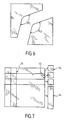
- the figure 6 represents two pieces of glazing after cutting according to the invention. It can be seen that the cutout comprises a rounded angle with a small radius of curvature producing in the two cut-out portions two angles perfectly fitting one into the other. This angle was achieved without hole formation prior to cutting. According to the prior art, it was known to make angles at 90 °, but by intersection of cutting lines intersecting, that is to say continuing after their meeting point.
- the figure 7 illustrates this way of carving a ordinary glass according to the prior art, from cutting lines (13) passing through the entire surface of the glazing, and leading to pieces (14) square or rectangular. All the parts thus cut have their convex angles, none of the cut pieces presents a concave angle.
- the tracing is carried out according to a line joining itself without coming into intersection with the outer edge of the glazing and leading to the cutting on the one hand of a solid shape and on the other hand a perforated shape , the outer contour of the perforated shape corresponding to the original outer contour of the glazing, the inner contour of the perforated shape corresponding to the outer contour of the solid shape.
- This solid form can be a circle or have a radius of curvature as already mentioned.
- the figure 8 illustrates this possibility.
- a solid shape (15) has been cut inside a plate which then appears as a perforated shape (16).
- the outer contour of the solid shape corresponds to the internal contour (17) of the perforated shape.
- the outer contour (18) of the holed shape is the same as the original plate before cutting.
- the solid shape may be a circle or may include a small radius of curvature as already mentioned.
- the solid shape may also comprise one or more angles as already mentioned, it being understood that the realization of these angles must be carried out under the conditions already mentioned, that is to say with the formation of a hole prior to cutting where without formation preliminary hole but respecting a minimum radius of curvature of 3 mm tracing.
- the polygonal shape can comprise three, four, five or six angles or more.
- the perforated shape thus has a frame shape, said frame shape comprising a square-shaped internal edge or rectangular and an outer border of square or rectangular shape.
- This frame also has a section of square or rectangular shape.
- the perforated shape (or frame) thus obtained may especially find an application as an insert between two windows as in flat screens field emission (so-called "FED" English Field Emission display).
- the holed shape may have an edge width ((19) on the figure 8 ) very weak, that is to say corresponding to what has already been said for the narrow strips.
- the solid shape may be separated from the holed form, preferably by extraction from the initial tracing side. The solid shape can usually be extracted by hand.
- a thermal extraction which consists in heating (for example between 90 and 220 ° C.) in a first step the whole of the cut glazing but for which the solid form and the perforated form have not yet been separated, then in a second time the central portion of the glazing comprising the solid form to be extracted is cooled. Retraction caused by cooling makes it easier to extract the solid form.
- the cutting according to the invention can be carried out from a surface tracing of a sheet of glass treated according to the invention (chemical treatment, or layer, or under flexion), said sheet being part of a glazing unit laminated.
- the crack caused by the tracing propagates through the thickness of the treated sheet and stops at the polymer spacer usually placed between the sheets of a laminated glazing unit.
- the cracks thus created play the role of mirror for the light passing through the glazing.
- the glazing thus obtained, of good aesthetic appearance, can serve as a light deflector.
- the figure 9 illustrates this application.
- the light rays (20) are reflected at the interfaces (21) of the cracks created according to the invention through the treated sheet (22) of the laminated glazing (23) associating two sheets of glass separated by a layer ( 24) of polymer.
- the cracks may for example be spaced from each other by 2 mm to 10 mm. Generally, it is sought that the distance between two cracks is 40 to 80% of the thickness of the cracked sheet.
- the present invention particularly when it involves a chemical quenching treatment is very interesting for cutting glazing in the electronic field.
- This chemical quenching technique is particularly applicable to glasses capable of exchanging ions, as is the case with glasses for electronics, in particular with a high point of viscosity ("strain point" in English), for example commercial CS77 glass. by Saint-Gobain Glass France.
- the composition of such glasses is for example described in EP 0914299 .
- the cutting technique is therefore applicable to the production lines of accessories for electronics (such as spacers or spacers), screens (plasma, LCD, TFT, FED), frames for field effect screens, manufacturing lines of vacuum glazing.
- the use of chemical quenching provides good mechanical strength of the edges, including cut edges.
- the glass plates have been cut with diamond or by a wheel in different cutting shapes corresponding to different applications. Cutouts with a wheel were all made on the following principle. Tracing is carried out with a VITRUM brand wheel sold by ADLER, said wheel having an angle of 145 ° and a diameter of 5 mm under cutting oil and under a load so that the sub-crack is deeper than the exchange depth P e .
- the sub-crack propagates throughout the thickness of the glass without the need to apply a breaking force (see "propagation" line in Table 1). ). In some cases, the propagation was initiated at the end of the tracing by an addition of water penetrating by capillarity into the sub-crack. In other cases, propagation has been initiated by increasing the load at the end of the trace.
- a laminated glazing unit is produced with, on the one hand, the chemically treated plate and, on the other hand, an ordinary (non-chemically treated) soda-lime glass 2 mm thick, by conventionally placing a layer of polyvinyl butyral (PVB) therebetween. .
- PVB polyvinyl butyral
- a first series of linear and parallel wheel tracings is performed on the side of the chemically tempered glazing, said tracings being spaced from each other by 8 mm and ending on the edge dipped in water. Water plays its role by initiating the propagation of each crack.
- a second series of tracing is then carried out, between the tracing of the first series, so that finally, the plate has tracings every 4 mm approximately. It can be seen that all cracks caused by tracing propagate to the PVB layer, that is to say through the entire thickness of the chemically hardened glass.
- the glazing can then act as a reflector of the light that passes through it thanks to the mirror effect of each of the cracks (see figure 9 ).
- a 60 mm diameter circle is cut from the chemically hardened glass using a VITRUM brand dial sold by ADLER, the said wheel having an angle of 145 ° and a diameter of 5 mm, the said wheel being mounted on a spinning wheel.
- the glass disk can be extracted by thermal extraction without causing breakage, neither to the disk nor to the rest of the plate.
- the 300 ⁇ m thick glass sheet is diamond-cut after chemical quenching, without initiation, by water or by increasing the charge. Cutting is done easily along the tracing without uncontrolled breakage.
- the K-factor in the glass was measured at the biasograph on strips 3 mm wide.
- Example 5 The procedure is as for Example 5 except that the chemical quenching is carried out so that the factor K reaches the value mentioned in Table 1.
Landscapes
- Chemical & Material Sciences (AREA)
- Engineering & Computer Science (AREA)
- Materials Engineering (AREA)
- Organic Chemistry (AREA)
- General Chemical & Material Sciences (AREA)
- Thermal Sciences (AREA)
- Life Sciences & Earth Sciences (AREA)
- Chemical Kinetics & Catalysis (AREA)
- Physics & Mathematics (AREA)
- Geochemistry & Mineralogy (AREA)
- Re-Forming, After-Treatment, Cutting And Transporting Of Glass Products (AREA)
- Processing Of Stones Or Stones Resemblance Materials (AREA)
- Joining Of Glass To Other Materials (AREA)
- Formation Of Insulating Films (AREA)
- Glass Compositions (AREA)
- Surface Treatment Of Glass (AREA)
- Liquid Crystal (AREA)
Claims (31)
- Verfahren zum Zuschneiden eines Glases, das eine zwei Hauptseiten umfassende Glasscheibe umfasst, in welchem keine Bruchkraft auftritt und welches die Stufen:- Behandeln der Glasscheibe, wodurch Spannungen, mindestens ein Druckbereich und mindestens ein Dehnungsbereich erzeugt werden, wobei die Spannungsverteilung in der Dicke biaxial ist, im Wesentlichen isotrop ist und automatisch ihr Gleichgewicht einstellt und diese Spannungen derart sind, dass der Faktor K 0,05 bis 0,4 MPa·m1/2 beträgt und durch

definiert ist, worin z eine Stelle in der Dicke, σz die Stärke der im Wesentlichen isotropen biaxialen Spannung an der Stelle z und H(σz) gleich 1, wenn σz größer als 0, und gleich 0, wenn σz kleiner als oder gleich 0, mit der Vereinbarung, dass eine Ausdehnung als positiv und ein Zusammendrücken als negativ gekennzeichnet wird, bedeutet, und anschließend- Anreißen einer Linie, die tiefer als 10 µm ist, entlang der gewünschten Zuschneidstrecke des behandelten Glases, wobei die Linie den Ausdehnungsbereich des Glases erreicht,umfasst. - Verfahren nach dem vorhergehenden Anspruch, dadurch gekennzeichnet, dass das Glas vor der Behandlung ein Alkalimetalloxid enthält und dass die Behandlung ein chemisches Vorspannen ist.
- Verfahren nach dem vorhergehenden Anspruch, dadurch gekennzeichnet, dass durch das chemische Vorspannen ein K+- oder Na+-Gradient erzeugt wird, der senkrecht zu mindestens einer der Hauptseiten verläuft und ab dieser Hauptseite abnimmt.
- Verfahren nach einem der zwei vorhergehenden Ansprüche, dadurch gekennzeichnet, dass durch das chemische Vorspannen über eine Tiefe von höchstens 50 µm ein Ionenaustausch bewirkt wird.
- Verfahren nach Anspruch 1, dadurch gekennzeichnet, dass die Behandlung das Aufbringen einer unter Druckspannungen stehenden Schicht ist.
- Verfahren nach dem vorhergehenden Anspruch, dadurch gekennzeichnet, dass die Dicke der Schicht 1 bis 20 µm beträgt.
- Verfahren nach dem vorhergehenden Anspruch, dadurch gekennzeichnet, dass die Schicht ein Spannung von 200 MPa bis 5 GPa enthält.
- Verfahren nach Anspruch 1, dadurch gekennzeichnet, dass die Behandlung im Einwirken von im Wesentlichen isotropen biaxialen Biegekräften besteht.
- Verfahren nach dem vorhergehenden Anspruch, dadurch gekennzeichnet, dass die Biegekräfte erzeugt werden durch die Kombination von einerseits der Anwendung unterschiedlicher Temperaturen auf die Hauptseiten und andererseits von Kräften, die der Verformung widerstehen, die von der Temperaturdifferenz verursacht wird.
- Verfahren nach einem der zwei vorhergehenden Ansprüche, dadurch gekennzeichnet, dass die Biegekräfte 3 bis 20 MPa betragen.
- Verfahren nach einem der vorhergehenden Ansprüche, dadurch gekennzeichnet, dass die Dicke des Glases 0,7 bis 5,2 mm beträgt.
- Verfahren nach dem vorhergehenden Anspruch, dadurch gekennzeichnet, dass die Dicke des Glases 2,6 bis 5,2 mm beträgt.
- Verfahren nach einem der vorhergehenden Ansprüche, dadurch gekennzeichnet, dass das Anreißen auf einer unter Druckspannungen stehenden Hauptseite durchgeführt wird und eine Anreißlinie erzeugt, die durch den Druckbereich führt, um den Ausdehnungsbereich zu erreichen.
- Verfahren nach einem der Ansprüche 1 bis 12, dadurch gekennzeichnet, dass das Anreißen auf einer unter Dehnungsspannungen stehenden Hauptseite durchgeführt wird.
- Verfahren nach einem der vorhergehenden Ansprüche, dadurch gekennzeichnet, dass das Anreißen entlang einer Linie durchgeführt wird, die sich mit sich selbst wieder vereinigt, ohne den Außenrand des Glases zu schneiden, und einerseits an den Ausschnitt einer vollen Form und andererseits einer Lochform anstößt, wobei der Außenumfang der Lochform dem ursprünglichen Außenumfang des Glases und der Innenumfang der Lochform dem Außenumfang der vollen Form entspricht.
- Verfahren nach einem der vorhergehenden Ansprüche, dadurch gekennzeichnet, dass das Anreißen entlang einer Linie durchgeführt wird, die an mindestens einer Stelle einen Krümmungsradius von kleiner als 5 mm aufweist.
- Glas, das eine zwei Hauptseiten und mindestens eine Schmalseite umfassende Glasscheibe umfasst und in der Dicke eine Verteilung der Spannungen aufweist, die biaxial sind, im Wesentlichen isotrop sind, automatisch ihr Gleichgewicht einstellen und deren Faktor K 0,05 bis 0,4 MPa·m1/2 beträgt und durch

definiert ist, worin z eine Stelle in der Dicke, σz die Spannung an der Stelle z und H(σz) gleich 1, wenn σz größer als 0, und gleich 0, wenn σz kleiner als oder gleich 0, mit der Vereinbarung, dass eine Ausdehnung als positiv und ein Zusammendrücken als negativ gekennzeichnet wird, bedeutet. - Glas nach dem vorhergehenden Anspruch, dadurch gekennzeichnet, dass es einen Alkalimetallionengradienten enthält, der senkrecht zu mindestens einer der Hauptseiten verläuft und ab dieser Hauptseite abnimmt.
- Glas nach dem vorhergehenden Anspruch, dadurch gekennzeichnet, dass der senkrecht zu mindestens einer der Hauptseiten verlaufende Gradient in der Fläche mindestens einer Schmalseite vorhanden ist.
- Glas nach dem vorhergehenden Anspruch, dadurch gekennzeichnet, dass die Schmalseite eine Anreißlinie für den Ausschnitt aufweist.
- Glas nach einem der es betreffenden vorhergehenden Ansprüche, dadurch gekennzeichnet, dass mindestens eine Schmalseite in der zu ihr senkrechten Richtung keinen Alkalimetallionengradienten enthält.
- Glas nach einem der es betreffenden vorhergehenden Ansprüche, dadurch gekennzeichnet, dass seine Dicke 0,7 bis 5,2 mm beträgt.
- Glas nach dem es betreffenden vorhergehenden Anspruch, dadurch gekennzeichnet, dass seine Dicke 2,6 bis 5,2 mm beträgt.
- Glas nach einem der es betreffenden vorhergehenden Ansprüche, dadurch gekennzeichnet, dass einer seiner Ränder an mindestens einer Stelle einen Krümmungsradius von kleiner als 5 mm aufweist.
- Glas nach einem der es betreffenden vorhergehenden Ansprüche, dadurch gekennzeichnet, dass es wenigstens teilweise in Form eines Bandes mit quadratischem oder rechteckigem Querschnitt vorliegt, das eine Breite aufweist, die kleiner als das 1,5 fache seiner Dicke ist.
- Glas nach dem vorhergehenden Anspruch, dadurch gekennzeichnet, dass es wenigstens teilweise eine Breite aufweist, die kleiner als das 1 fache seiner Dicke ist.
- Glas nach einem der es betreffenden vorhergehenden Ansprüche, dadurch gekennzeichnet, dass es die Form eines Rahmens mit quadratischem oder rechteckigem Querschnitt aufweist, wobei diese Rahmenform einen Innenrand mit quadratischer oder rechteckiger Form und einen Außenrand mit quadratischer oder rechteckiger Form umfasst.
- Feldemissionsdisplay, das ein Zwischenteil umfasst, das ein Glas nach dem vorhergehenden Anspruch umfasst.
- Verbundglas, wovon eine der Glasscheiben ein Glas nach einem der Ansprüche 17 bis 19 ist und eine Vielzahl von parallelen geraden Rissen umfasst, die durch sie bis zur Kunststoffzwischenschicht hindurchgehen.
- Glas nach dem vorhergehenden Anspruch, dadurch gekennzeichnet, dass die Abstände zwischen den Rissen 2 bis 10 mm betragen.
- Glas nach einem der zwei vorhergehenden Ansprüche, dadurch gekennzeichnet, dass der Abstand zwischen zwei Rissen 40 bis 80 % der Dicke der mit Rissen versehenen Glasscheibe ausmacht.
Applications Claiming Priority (3)
| Application Number | Priority Date | Filing Date | Title |
|---|---|---|---|
| FR0205956A FR2839508B1 (fr) | 2002-05-07 | 2002-05-07 | Vitrage decoupe sans rompage |
| FR0205956 | 2002-05-07 | ||
| PCT/FR2003/001417 WO2003095378A2 (fr) | 2002-05-07 | 2003-05-07 | Procede de decoupe d’un vitrage sans application d’une force de rompage et vitrage obtenu par le procede |
Publications (2)
| Publication Number | Publication Date |
|---|---|
| EP1501766A2 EP1501766A2 (de) | 2005-02-02 |
| EP1501766B1 true EP1501766B1 (de) | 2009-02-18 |
Family
ID=29286499
Family Applications (1)
| Application Number | Title | Priority Date | Filing Date |
|---|---|---|---|
| EP03749931A Expired - Lifetime EP1501766B1 (de) | 2002-05-07 | 2003-05-07 | Glasschneideverfahren ohne brechen |
Country Status (10)
| Country | Link |
|---|---|
| US (1) | US20050221044A1 (de) |
| EP (1) | EP1501766B1 (de) |
| JP (1) | JP2006509701A (de) |
| CN (1) | CN1930097A (de) |
| AT (1) | ATE423084T1 (de) |
| AU (1) | AU2003254525A1 (de) |
| DE (1) | DE60326227D1 (de) |
| FR (1) | FR2839508B1 (de) |
| PL (1) | PL372842A1 (de) |
| WO (1) | WO2003095378A2 (de) |
Families Citing this family (73)
| Publication number | Priority date | Publication date | Assignee | Title |
|---|---|---|---|---|
| CN100468198C (zh) * | 2004-04-02 | 2009-03-11 | 鸿富锦精密工业(深圳)有限公司 | 薄膜工件的切割方法 |
| TWI577653B (zh) * | 2007-03-02 | 2017-04-11 | 日本電氣硝子股份有限公司 | 強化板玻璃及其製造方法 |
| JP5467490B2 (ja) * | 2007-08-03 | 2014-04-09 | 日本電気硝子株式会社 | 強化ガラス基板の製造方法及び強化ガラス基板 |
| US9346130B2 (en) | 2008-12-17 | 2016-05-24 | Electro Scientific Industries, Inc. | Method for laser processing glass with a chamfered edge |
| US8341976B2 (en) * | 2009-02-19 | 2013-01-01 | Corning Incorporated | Method of separating strengthened glass |
| US8347651B2 (en) * | 2009-02-19 | 2013-01-08 | Corning Incorporated | Method of separating strengthened glass |
| US8327666B2 (en) * | 2009-02-19 | 2012-12-11 | Corning Incorporated | Method of separating strengthened glass |
| JP5616907B2 (ja) | 2009-03-02 | 2014-10-29 | アップル インコーポレイテッド | ポータブル電子デバイスのガラスカバーを強化する技術 |
| US20110019354A1 (en) * | 2009-03-02 | 2011-01-27 | Christopher Prest | Techniques for Strengthening Glass Covers for Portable Electronic Devices |
| WO2011025908A1 (en) | 2009-08-28 | 2011-03-03 | Corning Incorporated | Methods for laser cutting articles from chemically strengthened glass substrates |
| US8932510B2 (en) | 2009-08-28 | 2015-01-13 | Corning Incorporated | Methods for laser cutting glass substrates |
| JP2013505890A (ja) * | 2009-09-29 | 2013-02-21 | ピコドリル エスアー | 基板を切断する方法及び切断のための装置 |
| EP2507182B1 (de) * | 2009-11-30 | 2014-03-05 | Corning Incorporated | Verfahren zum schneiden und teilen von glasubstraten mittels laservorrichtung |
| US8946590B2 (en) * | 2009-11-30 | 2015-02-03 | Corning Incorporated | Methods for laser scribing and separating glass substrates |
| TWI438162B (zh) | 2010-01-27 | 2014-05-21 | Wintek Corp | 強化玻璃切割方法及強化玻璃切割預置結構 |
| BR112012019306A2 (pt) * | 2010-02-02 | 2018-05-08 | Apple Inc | vidro de reforço melhorado quimicamente de coberturas para dispositivos eletrônicos portáteis |
| TWI494284B (zh) * | 2010-03-19 | 2015-08-01 | Corning Inc | 強化玻璃之機械劃割及分離 |
| TWI524244B (zh) * | 2010-05-04 | 2016-03-01 | 永恆科技有限公司 | Touch panel and manufacturing method thereof |
| CN102294654B (zh) * | 2010-06-23 | 2014-07-16 | 鸿富锦精密工业(深圳)有限公司 | 喷砂装置及采用该喷砂装置成型制品的加工方法 |
| US8864005B2 (en) * | 2010-07-16 | 2014-10-21 | Corning Incorporated | Methods for scribing and separating strengthened glass substrates |
| US8720228B2 (en) | 2010-08-31 | 2014-05-13 | Corning Incorporated | Methods of separating strengthened glass substrates |
| CN101948241A (zh) * | 2010-09-02 | 2011-01-19 | 东莞市飞尔液晶显示器有限公司 | 一种液晶显示屏切割工艺 |
| CN102442764A (zh) * | 2010-10-08 | 2012-05-09 | 东莞万士达液晶显示器有限公司 | 强化玻璃切割方法及强化玻璃切割预置结构 |
| WO2012051485A1 (en) | 2010-10-16 | 2012-04-19 | Cambridge Nanotech Inc. | Ald coating system |
| US8616024B2 (en) * | 2010-11-30 | 2013-12-31 | Corning Incorporated | Methods for forming grooves and separating strengthened glass substrate sheets |
| US8607590B2 (en) * | 2010-11-30 | 2013-12-17 | Corning Incorporated | Methods for separating glass articles from strengthened glass substrate sheets |
| US8539794B2 (en) | 2011-02-01 | 2013-09-24 | Corning Incorporated | Strengthened glass substrate sheets and methods for fabricating glass panels from glass substrate sheets |
| US8776547B2 (en) | 2011-02-28 | 2014-07-15 | Corning Incorporated | Local strengthening of glass by ion exchange |
| US8635887B2 (en) * | 2011-08-10 | 2014-01-28 | Corning Incorporated | Methods for separating glass substrate sheets by laser-formed grooves |
| JP5783873B2 (ja) * | 2011-10-04 | 2015-09-24 | 三星ダイヤモンド工業株式会社 | ガラス基板のスクライブ方法 |
| US10357850B2 (en) | 2012-09-24 | 2019-07-23 | Electro Scientific Industries, Inc. | Method and apparatus for machining a workpiece |
| US9828278B2 (en) | 2012-02-28 | 2017-11-28 | Electro Scientific Industries, Inc. | Method and apparatus for separation of strengthened glass and articles produced thereby |
| CN104136967B (zh) | 2012-02-28 | 2018-02-16 | 伊雷克托科学工业股份有限公司 | 用于分离增强玻璃的方法及装置及由该增强玻璃生产的物品 |
| US9359251B2 (en) | 2012-02-29 | 2016-06-07 | Corning Incorporated | Ion exchanged glasses via non-error function compressive stress profiles |
| WO2013130608A1 (en) * | 2012-02-29 | 2013-09-06 | Electro Scientific Industries, Inc. | Methods and apparatus for machining strengthened glass and articles produced thereby |
| US10351460B2 (en) | 2012-05-22 | 2019-07-16 | Corning Incorporated | Methods of separating strengthened glass sheets by mechanical scribing |
| US9938180B2 (en) | 2012-06-05 | 2018-04-10 | Corning Incorporated | Methods of cutting glass using a laser |
| KR101395054B1 (ko) | 2012-08-08 | 2014-05-14 | 삼성코닝정밀소재 주식회사 | 강화유리 커팅 방법 및 강화유리 커팅용 스테이지 |
| US9610653B2 (en) | 2012-09-21 | 2017-04-04 | Electro Scientific Industries, Inc. | Method and apparatus for separation of workpieces and articles produced thereby |
| EP2754524B1 (de) | 2013-01-15 | 2015-11-25 | Corning Laser Technologies GmbH | Verfahren und Vorrichtung zum laserbasierten Bearbeiten von flächigen Substraten, d.h. Wafer oder Glaselement, unter Verwendung einer Laserstrahlbrennlinie |
| JP6071024B2 (ja) | 2013-02-25 | 2017-02-01 | コーニング インコーポレイテッド | 薄いガラス板を製造する方法 |
| EP2781296B1 (de) | 2013-03-21 | 2020-10-21 | Corning Laser Technologies GmbH | Vorrichtung und verfahren zum ausschneiden von konturen aus flächigen substraten mittels laser |
| JP2015027933A (ja) * | 2013-06-27 | 2015-02-12 | 日本電気硝子株式会社 | 強化ガラス板のスクライブ方法 |
| US11079309B2 (en) | 2013-07-26 | 2021-08-03 | Corning Incorporated | Strengthened glass articles having improved survivability |
| KR101484091B1 (ko) * | 2013-11-04 | 2015-01-19 | 코닝정밀소재 주식회사 | 강화유리 절단방법 및 강화유리 절단장치 |
| WO2015113024A1 (en) * | 2014-01-27 | 2015-07-30 | Corning Incorporated | Edge chamfering methods |
| US10442719B2 (en) | 2013-12-17 | 2019-10-15 | Corning Incorporated | Edge chamfering methods |
| US10293436B2 (en) | 2013-12-17 | 2019-05-21 | Corning Incorporated | Method for rapid laser drilling of holes in glass and products made therefrom |
| US11556039B2 (en) | 2013-12-17 | 2023-01-17 | Corning Incorporated | Electrochromic coated glass articles and methods for laser processing the same |
| CN106458693B (zh) * | 2014-02-20 | 2020-06-16 | 康宁股份有限公司 | 用于在柔性薄玻璃中切割多个半径的方法和设备 |
| US10118858B2 (en) | 2014-02-24 | 2018-11-06 | Corning Incorporated | Strengthened glass with deep depth of compression |
| US9776906B2 (en) | 2014-03-28 | 2017-10-03 | Electro Scientific Industries, Inc. | Laser machining strengthened glass |
| US10927031B2 (en) * | 2014-03-31 | 2021-02-23 | Mitsuboshi Diamond Industrial Co., Ltd. | Method for dividing brittle-material substrate |
| TWI852054B (zh) | 2014-06-19 | 2024-08-11 | 美商康寧公司 | 無易碎應力分布曲線的玻璃 |
| KR102445217B1 (ko) | 2014-07-08 | 2022-09-20 | 코닝 인코포레이티드 | 재료를 레이저 가공하는 방법 및 장치 |
| LT3169477T (lt) | 2014-07-14 | 2020-05-25 | Corning Incorporated | Skaidrių medžiagų apdorojimo sistema ir būdas, naudojant lazerio pluošto židinio linijas, kurių ilgis ir skersmuo yra reguliuojami |
| TWI749406B (zh) | 2014-10-08 | 2021-12-11 | 美商康寧公司 | 含有金屬氧化物濃度梯度之玻璃以及玻璃陶瓷 |
| US10150698B2 (en) | 2014-10-31 | 2018-12-11 | Corning Incorporated | Strengthened glass with ultra deep depth of compression |
| JP6839077B2 (ja) | 2014-11-04 | 2021-03-03 | コーニング インコーポレイテッド | 深部非脆弱性応力プロファイル及びその作成方法 |
| US10017411B2 (en) | 2014-11-19 | 2018-07-10 | Corning Incorporated | Methods of separating a glass web |
| WO2016154284A1 (en) | 2015-03-24 | 2016-09-29 | Corning Incorporated | Laser cutting and processing of display glass compositions |
| US10579106B2 (en) | 2015-07-21 | 2020-03-03 | Corning Incorporated | Glass articles exhibiting improved fracture performance |
| US11613103B2 (en) | 2015-07-21 | 2023-03-28 | Corning Incorporated | Glass articles exhibiting improved fracture performance |
| EP3386930B1 (de) | 2015-12-11 | 2021-06-16 | Corning Incorporated | Fusionsformbare glasbasierte artikel mit einem metalloxidkonzentrationsgradienten |
| CN109071316B (zh) | 2016-04-08 | 2020-03-27 | 康宁股份有限公司 | 包含金属氧化物浓度梯度的玻璃基制品 |
| EP3397597B1 (de) | 2016-04-08 | 2023-11-08 | Corning Incorporated | Artikel auf glasbasis mit einem spannungsprofil mit zwei regionen und verfahren zur herstellung |
| WO2018064409A1 (en) | 2016-09-30 | 2018-04-05 | Corning Incorporated | Apparatuses and methods for laser processing transparent workpieces using non-axisymmetric beam spots |
| LT3529214T (lt) | 2016-10-24 | 2021-02-25 | Corning Incorporated | Substrato apdorojimo stotis lakšto formos stiklo substratų lazeriniam mašininiam apdorojimui |
| JP7134182B2 (ja) | 2017-03-22 | 2022-09-09 | コーニング インコーポレイテッド | ガラスウェブを分割する方法 |
| CN109553290B (zh) * | 2019-01-22 | 2024-04-26 | 安徽瑞龙玻璃机械股份有限公司 | 一种能够对切的玻璃切割机 |
| CN110156308B (zh) * | 2019-03-25 | 2023-09-22 | 洛阳兰迪玻璃机器股份有限公司 | 一种反弯钢化玻璃压片装置 |
| CN110092576B (zh) * | 2019-05-30 | 2021-12-28 | Tcl华星光电技术有限公司 | 切割装置及显示面板组件切割方法 |
| KR102860429B1 (ko) * | 2021-04-09 | 2025-09-16 | 코닝 인코포레이티드 | 글라스 패널 제조방법 |
Family Cites Families (14)
| Publication number | Priority date | Publication date | Assignee | Title |
|---|---|---|---|---|
| DE666861C (de) * | 1935-02-11 | 1938-10-29 | Compagnies Reunies Des Glaces | Verfahren zum Herstellen gehaerteter Glastafeln beliebig grosser Abmessungen |
| BE524291A (de) * | 1951-04-21 | |||
| FR1598242A (de) * | 1968-11-29 | 1970-07-06 | ||
| BE743569A (de) * | 1968-12-24 | 1970-06-22 | ||
| BE753189A (fr) * | 1969-07-10 | 1970-12-16 | Asahi Glass Co Ltd | Procede de renforcement d'un article en verre par echange d'ions et produit ainsi obtenu |
| FR2053664A6 (en) * | 1969-07-11 | 1971-04-16 | Long Bernard | Annealing/cutting device for glass sheet |
| FR2063482A5 (en) * | 1969-10-17 | 1971-07-09 | Long Bernard | Quench-cutting of continuous glass strips |
| US4018372A (en) * | 1975-12-05 | 1977-04-19 | The Fletcher-Terry Company | Glass cutting method and apparatus |
| DE3615287A1 (de) * | 1986-05-06 | 1987-11-12 | Schott Ruhrglas | Glasgefaess, insbesondere ampulle, und verfahren zur behandlung dieses glasgefaesses |
| RU2024441C1 (ru) * | 1992-04-02 | 1994-12-15 | Владимир Степанович Кондратенко | Способ резки неметаллических материалов |
| US5254149A (en) * | 1992-04-06 | 1993-10-19 | Ford Motor Company | Process for determining the quality of temper of a glass sheet using a laser beam |
| US6713180B1 (en) * | 1999-09-01 | 2004-03-30 | Pilkington Plc | Improvements in or relating to tempered glazings and glass for use therein |
| ATE392984T1 (de) * | 1999-11-24 | 2008-05-15 | Applied Photonics Inc | Verfahren und vorrichtung zum trennen nichtmetallischer materialien |
| DE10013693B4 (de) * | 2000-03-21 | 2004-12-09 | Fraunhofer-Gesellschaft zur Förderung der angewandten Forschung e.V. | Verfahren zur Herstellung einer aus anorganischem Glas bestehenden Schnittstreckerplatte |
-
2002
- 2002-05-07 FR FR0205956A patent/FR2839508B1/fr not_active Expired - Fee Related
-
2003
- 2003-05-07 AU AU2003254525A patent/AU2003254525A1/en not_active Abandoned
- 2003-05-07 PL PL03372842A patent/PL372842A1/xx unknown
- 2003-05-07 AT AT03749931T patent/ATE423084T1/de not_active IP Right Cessation
- 2003-05-07 CN CNA038104105A patent/CN1930097A/zh active Pending
- 2003-05-07 EP EP03749931A patent/EP1501766B1/de not_active Expired - Lifetime
- 2003-05-07 US US10/513,022 patent/US20050221044A1/en not_active Abandoned
- 2003-05-07 DE DE60326227T patent/DE60326227D1/de not_active Expired - Fee Related
- 2003-05-07 WO PCT/FR2003/001417 patent/WO2003095378A2/fr not_active Ceased
- 2003-05-07 JP JP2004503405A patent/JP2006509701A/ja active Pending
Also Published As
| Publication number | Publication date |
|---|---|
| CN1930097A (zh) | 2007-03-14 |
| AU2003254525A8 (en) | 2003-11-11 |
| FR2839508A1 (fr) | 2003-11-14 |
| DE60326227D1 (de) | 2009-04-02 |
| JP2006509701A (ja) | 2006-03-23 |
| WO2003095378A3 (fr) | 2004-04-22 |
| WO2003095378A2 (fr) | 2003-11-20 |
| FR2839508B1 (fr) | 2005-03-04 |
| ATE423084T1 (de) | 2009-03-15 |
| US20050221044A1 (en) | 2005-10-06 |
| PL372842A1 (en) | 2005-08-08 |
| EP1501766A2 (de) | 2005-02-02 |
| AU2003254525A1 (en) | 2003-11-11 |
Similar Documents
| Publication | Publication Date | Title |
|---|---|---|
| EP1501766A2 (de) | Glasschneideverfahren ohne brechen | |
| EP3044177B1 (de) | Bruchsichere geschichtete substrate und diese enthaltende artikel | |
| JP7225329B2 (ja) | 薄厚熱強化及び化学強化ガラス系物品 | |
| EP3589598B1 (de) | Asymmetrische spannungsprofile für verzugsarme glasartikel mit hohem bruchwiderstand | |
| KR101945583B1 (ko) | 중등 접착력 및 잔류 강도를 갖는 적층 제품 | |
| JP6315305B2 (ja) | ガラス積層体及びこれを用いた光学結像部材 | |
| US20160207825A1 (en) | Laminates with a polymeric scratch resistant layer | |
| TW201733954A (zh) | 超薄非易碎的玻璃及製造方法 | |
| CN116553809B (zh) | 低存储拉伸能切割玻璃和优先裂纹碎裂玻璃 | |
| TW201040117A (en) | Method of separating strengthened glass | |
| US12060298B2 (en) | Glass compositions and methods with steam treatment haze resistance | |
| WO2020227924A1 (en) | Thin glass substrate with high bending strength and method for producing same | |
| TW202134197A (zh) | 高度易碎玻璃之應力變化圖 | |
| TW202012331A (zh) | 用於微電子製造的載具 | |
| WO2017132491A1 (en) | Thermally strengthened photochromic glass and related systems and methods | |
| JP7315567B2 (ja) | 被覆化学強化ガラス物品の製造方法 | |
| KR20050016393A (ko) | 파단을 일으키지 않는 유리 절단 방법 | |
| US20210269351A1 (en) | Handheld sheet edge strip separation devices and methods of separating glass sheets | |
| US12630473B2 (en) | Thin glass substrate with high bending strength and method for producing same | |
| KR20250117394A (ko) | 내충격성 유리 중합체 층 및 내손상성 유리 적층체 층을 갖는 복합 물품 및 이의 제조 방법 |
Legal Events
| Date | Code | Title | Description |
|---|---|---|---|
| PUAI | Public reference made under article 153(3) epc to a published international application that has entered the european phase |
Free format text: ORIGINAL CODE: 0009012 |
|
| 17P | Request for examination filed |
Effective date: 20041005 |
|
| AK | Designated contracting states |
Kind code of ref document: A2 Designated state(s): AT BE BG CH CY CZ DE DK EE ES FI FR GB GR HU IE IT LI LU MC NL PT RO SE SI SK TR |
|
| AX | Request for extension of the european patent |
Extension state: AL LT LV MK |
|
| RIN1 | Information on inventor provided before grant (corrected) |
Inventor name: GAUME, OLIVIER Inventor name: VALLADEAU, SERGE |
|
| DAX | Request for extension of the european patent (deleted) | ||
| 17Q | First examination report despatched |
Effective date: 20071220 |
|
| GRAP | Despatch of communication of intention to grant a patent |
Free format text: ORIGINAL CODE: EPIDOSNIGR1 |
|
| GRAS | Grant fee paid |
Free format text: ORIGINAL CODE: EPIDOSNIGR3 |
|
| GRAA | (expected) grant |
Free format text: ORIGINAL CODE: 0009210 |
|
| AK | Designated contracting states |
Kind code of ref document: B1 Designated state(s): AT BE BG CH CY CZ DE DK EE ES FI FR GB GR HU IE IT LI LU MC NL PT RO SE SI SK TR |
|
| REG | Reference to a national code |
Ref country code: GB Ref legal event code: FG4D Free format text: NOT ENGLISH |
|
| REG | Reference to a national code |
Ref country code: CH Ref legal event code: EP |
|
| REG | Reference to a national code |
Ref country code: IE Ref legal event code: FG4D Free format text: LANGUAGE OF EP DOCUMENT: FRENCH |
|
| REF | Corresponds to: |
Ref document number: 60326227 Country of ref document: DE Date of ref document: 20090402 Kind code of ref document: P |
|
| PG25 | Lapsed in a contracting state [announced via postgrant information from national office to epo] |
Ref country code: FI Free format text: LAPSE BECAUSE OF FAILURE TO SUBMIT A TRANSLATION OF THE DESCRIPTION OR TO PAY THE FEE WITHIN THE PRESCRIBED TIME-LIMIT Effective date: 20090218 Ref country code: NL Free format text: LAPSE BECAUSE OF FAILURE TO SUBMIT A TRANSLATION OF THE DESCRIPTION OR TO PAY THE FEE WITHIN THE PRESCRIBED TIME-LIMIT Effective date: 20090218 Ref country code: SI Free format text: LAPSE BECAUSE OF FAILURE TO SUBMIT A TRANSLATION OF THE DESCRIPTION OR TO PAY THE FEE WITHIN THE PRESCRIBED TIME-LIMIT Effective date: 20090218 Ref country code: ES Free format text: LAPSE BECAUSE OF FAILURE TO SUBMIT A TRANSLATION OF THE DESCRIPTION OR TO PAY THE FEE WITHIN THE PRESCRIBED TIME-LIMIT Effective date: 20090529 |
|
| NLV1 | Nl: lapsed or annulled due to failure to fulfill the requirements of art. 29p and 29m of the patents act | ||
| PG25 | Lapsed in a contracting state [announced via postgrant information from national office to epo] |
Ref country code: SE Free format text: LAPSE BECAUSE OF FAILURE TO SUBMIT A TRANSLATION OF THE DESCRIPTION OR TO PAY THE FEE WITHIN THE PRESCRIBED TIME-LIMIT Effective date: 20090518 Ref country code: AT Free format text: LAPSE BECAUSE OF FAILURE TO SUBMIT A TRANSLATION OF THE DESCRIPTION OR TO PAY THE FEE WITHIN THE PRESCRIBED TIME-LIMIT Effective date: 20090218 |
|
| REG | Reference to a national code |
Ref country code: IE Ref legal event code: FD4D |
|
| PG25 | Lapsed in a contracting state [announced via postgrant information from national office to epo] |
Ref country code: CZ Free format text: LAPSE BECAUSE OF FAILURE TO SUBMIT A TRANSLATION OF THE DESCRIPTION OR TO PAY THE FEE WITHIN THE PRESCRIBED TIME-LIMIT Effective date: 20090218 Ref country code: PT Free format text: LAPSE BECAUSE OF FAILURE TO SUBMIT A TRANSLATION OF THE DESCRIPTION OR TO PAY THE FEE WITHIN THE PRESCRIBED TIME-LIMIT Effective date: 20090727 Ref country code: DK Free format text: LAPSE BECAUSE OF FAILURE TO SUBMIT A TRANSLATION OF THE DESCRIPTION OR TO PAY THE FEE WITHIN THE PRESCRIBED TIME-LIMIT Effective date: 20090218 Ref country code: IE Free format text: LAPSE BECAUSE OF FAILURE TO SUBMIT A TRANSLATION OF THE DESCRIPTION OR TO PAY THE FEE WITHIN THE PRESCRIBED TIME-LIMIT Effective date: 20090218 Ref country code: EE Free format text: LAPSE BECAUSE OF FAILURE TO SUBMIT A TRANSLATION OF THE DESCRIPTION OR TO PAY THE FEE WITHIN THE PRESCRIBED TIME-LIMIT Effective date: 20090218 |
|
| BERE | Be: lapsed |
Owner name: SAINT-GOBAIN GLASS FRANCE Effective date: 20090531 |
|
| PG25 | Lapsed in a contracting state [announced via postgrant information from national office to epo] |
Ref country code: RO Free format text: LAPSE BECAUSE OF FAILURE TO SUBMIT A TRANSLATION OF THE DESCRIPTION OR TO PAY THE FEE WITHIN THE PRESCRIBED TIME-LIMIT Effective date: 20090218 Ref country code: SK Free format text: LAPSE BECAUSE OF FAILURE TO SUBMIT A TRANSLATION OF THE DESCRIPTION OR TO PAY THE FEE WITHIN THE PRESCRIBED TIME-LIMIT Effective date: 20090218 |
|
| PLBE | No opposition filed within time limit |
Free format text: ORIGINAL CODE: 0009261 |
|
| STAA | Information on the status of an ep patent application or granted ep patent |
Free format text: STATUS: NO OPPOSITION FILED WITHIN TIME LIMIT |
|
| PG25 | Lapsed in a contracting state [announced via postgrant information from national office to epo] |
Ref country code: MC Free format text: LAPSE BECAUSE OF NON-PAYMENT OF DUE FEES Effective date: 20090531 |
|
| REG | Reference to a national code |
Ref country code: CH Ref legal event code: PL |
|
| 26N | No opposition filed |
Effective date: 20091119 |
|
| GBPC | Gb: european patent ceased through non-payment of renewal fee |
Effective date: 20090518 |
|
| PG25 | Lapsed in a contracting state [announced via postgrant information from national office to epo] |
Ref country code: BG Free format text: LAPSE BECAUSE OF FAILURE TO SUBMIT A TRANSLATION OF THE DESCRIPTION OR TO PAY THE FEE WITHIN THE PRESCRIBED TIME-LIMIT Effective date: 20090518 Ref country code: CH Free format text: LAPSE BECAUSE OF NON-PAYMENT OF DUE FEES Effective date: 20090531 Ref country code: LI Free format text: LAPSE BECAUSE OF NON-PAYMENT OF DUE FEES Effective date: 20090531 |
|
| REG | Reference to a national code |
Ref country code: FR Ref legal event code: ST Effective date: 20100129 |
|
| PG25 | Lapsed in a contracting state [announced via postgrant information from national office to epo] |
Ref country code: FR Free format text: LAPSE BECAUSE OF NON-PAYMENT OF DUE FEES Effective date: 20090602 |
|
| PG25 | Lapsed in a contracting state [announced via postgrant information from national office to epo] |
Ref country code: GB Free format text: LAPSE BECAUSE OF NON-PAYMENT OF DUE FEES Effective date: 20090518 |
|
| PG25 | Lapsed in a contracting state [announced via postgrant information from national office to epo] |
Ref country code: BE Free format text: LAPSE BECAUSE OF NON-PAYMENT OF DUE FEES Effective date: 20090531 Ref country code: DE Free format text: LAPSE BECAUSE OF NON-PAYMENT OF DUE FEES Effective date: 20091201 |
|
| PG25 | Lapsed in a contracting state [announced via postgrant information from national office to epo] |
Ref country code: GR Free format text: LAPSE BECAUSE OF FAILURE TO SUBMIT A TRANSLATION OF THE DESCRIPTION OR TO PAY THE FEE WITHIN THE PRESCRIBED TIME-LIMIT Effective date: 20090519 |
|
| PG25 | Lapsed in a contracting state [announced via postgrant information from national office to epo] |
Ref country code: IT Free format text: LAPSE BECAUSE OF FAILURE TO SUBMIT A TRANSLATION OF THE DESCRIPTION OR TO PAY THE FEE WITHIN THE PRESCRIBED TIME-LIMIT Effective date: 20090218 |
|
| PG25 | Lapsed in a contracting state [announced via postgrant information from national office to epo] |
Ref country code: LU Free format text: LAPSE BECAUSE OF NON-PAYMENT OF DUE FEES Effective date: 20090507 |
|
| PG25 | Lapsed in a contracting state [announced via postgrant information from national office to epo] |
Ref country code: HU Free format text: LAPSE BECAUSE OF FAILURE TO SUBMIT A TRANSLATION OF THE DESCRIPTION OR TO PAY THE FEE WITHIN THE PRESCRIBED TIME-LIMIT Effective date: 20090819 |
|
| PG25 | Lapsed in a contracting state [announced via postgrant information from national office to epo] |
Ref country code: TR Free format text: LAPSE BECAUSE OF FAILURE TO SUBMIT A TRANSLATION OF THE DESCRIPTION OR TO PAY THE FEE WITHIN THE PRESCRIBED TIME-LIMIT Effective date: 20090218 |
|
| PG25 | Lapsed in a contracting state [announced via postgrant information from national office to epo] |
Ref country code: CY Free format text: LAPSE BECAUSE OF FAILURE TO SUBMIT A TRANSLATION OF THE DESCRIPTION OR TO PAY THE FEE WITHIN THE PRESCRIBED TIME-LIMIT Effective date: 20090218 |