EP1501453B2 - Höhenverstellbares implantat zum einsetzen zwischen wirbelkörpern und handhabungswerkzeug - Google Patents
Höhenverstellbares implantat zum einsetzen zwischen wirbelkörpern und handhabungswerkzeug Download PDFInfo
- Publication number
- EP1501453B2 EP1501453B2 EP04732110A EP04732110A EP1501453B2 EP 1501453 B2 EP1501453 B2 EP 1501453B2 EP 04732110 A EP04732110 A EP 04732110A EP 04732110 A EP04732110 A EP 04732110A EP 1501453 B2 EP1501453 B2 EP 1501453B2
- Authority
- EP
- European Patent Office
- Prior art keywords
- sleeve part
- nut
- implant
- sleeve
- face
- Prior art date
- Legal status (The legal status is an assumption and is not a legal conclusion. Google has not performed a legal analysis and makes no representation as to the accuracy of the status listed.)
- Expired - Lifetime
Links
Images


Classifications
-
- A—HUMAN NECESSITIES
- A61—MEDICAL OR VETERINARY SCIENCE; HYGIENE
- A61F—FILTERS IMPLANTABLE INTO BLOOD VESSELS; PROSTHESES; DEVICES PROVIDING PATENCY TO, OR PREVENTING COLLAPSING OF, TUBULAR STRUCTURES OF THE BODY, e.g. STENTS; ORTHOPAEDIC, NURSING OR CONTRACEPTIVE DEVICES; FOMENTATION; TREATMENT OR PROTECTION OF EYES OR EARS; BANDAGES, DRESSINGS OR ABSORBENT PADS; FIRST-AID KITS
- A61F2/00—Filters implantable into blood vessels; Prostheses, i.e. artificial substitutes or replacements for parts of the body; Appliances for connecting them with the body; Devices providing patency to, or preventing collapsing of, tubular structures of the body, e.g. stents
- A61F2/02—Prostheses implantable into the body
- A61F2/30—Joints
- A61F2/46—Special tools for implanting artificial joints
- A61F2/4603—Special tools for implanting artificial joints for insertion or extraction of endoprosthetic joints or of accessories thereof
- A61F2/4611—Special tools for implanting artificial joints for insertion or extraction of endoprosthetic joints or of accessories thereof of spinal prostheses
-
- A—HUMAN NECESSITIES
- A61—MEDICAL OR VETERINARY SCIENCE; HYGIENE
- A61F—FILTERS IMPLANTABLE INTO BLOOD VESSELS; PROSTHESES; DEVICES PROVIDING PATENCY TO, OR PREVENTING COLLAPSING OF, TUBULAR STRUCTURES OF THE BODY, e.g. STENTS; ORTHOPAEDIC, NURSING OR CONTRACEPTIVE DEVICES; FOMENTATION; TREATMENT OR PROTECTION OF EYES OR EARS; BANDAGES, DRESSINGS OR ABSORBENT PADS; FIRST-AID KITS
- A61F2/00—Filters implantable into blood vessels; Prostheses, i.e. artificial substitutes or replacements for parts of the body; Appliances for connecting them with the body; Devices providing patency to, or preventing collapsing of, tubular structures of the body, e.g. stents
- A61F2/02—Prostheses implantable into the body
- A61F2/30—Joints
- A61F2/44—Joints for the spine, e.g. vertebrae, spinal discs
-
- A—HUMAN NECESSITIES
- A61—MEDICAL OR VETERINARY SCIENCE; HYGIENE
- A61F—FILTERS IMPLANTABLE INTO BLOOD VESSELS; PROSTHESES; DEVICES PROVIDING PATENCY TO, OR PREVENTING COLLAPSING OF, TUBULAR STRUCTURES OF THE BODY, e.g. STENTS; ORTHOPAEDIC, NURSING OR CONTRACEPTIVE DEVICES; FOMENTATION; TREATMENT OR PROTECTION OF EYES OR EARS; BANDAGES, DRESSINGS OR ABSORBENT PADS; FIRST-AID KITS
- A61F2/00—Filters implantable into blood vessels; Prostheses, i.e. artificial substitutes or replacements for parts of the body; Appliances for connecting them with the body; Devices providing patency to, or preventing collapsing of, tubular structures of the body, e.g. stents
- A61F2/02—Prostheses implantable into the body
- A61F2/30—Joints
- A61F2/30721—Accessories
- A61F2/30744—End caps, e.g. for closing an endoprosthetic cavity
-
- A—HUMAN NECESSITIES
- A61—MEDICAL OR VETERINARY SCIENCE; HYGIENE
- A61F—FILTERS IMPLANTABLE INTO BLOOD VESSELS; PROSTHESES; DEVICES PROVIDING PATENCY TO, OR PREVENTING COLLAPSING OF, TUBULAR STRUCTURES OF THE BODY, e.g. STENTS; ORTHOPAEDIC, NURSING OR CONTRACEPTIVE DEVICES; FOMENTATION; TREATMENT OR PROTECTION OF EYES OR EARS; BANDAGES, DRESSINGS OR ABSORBENT PADS; FIRST-AID KITS
- A61F2/00—Filters implantable into blood vessels; Prostheses, i.e. artificial substitutes or replacements for parts of the body; Appliances for connecting them with the body; Devices providing patency to, or preventing collapsing of, tubular structures of the body, e.g. stents
- A61F2/02—Prostheses implantable into the body
- A61F2/30—Joints
- A61F2/44—Joints for the spine, e.g. vertebrae, spinal discs
- A61F2/442—Intervertebral or spinal discs, e.g. resilient
-
- A—HUMAN NECESSITIES
- A61—MEDICAL OR VETERINARY SCIENCE; HYGIENE
- A61F—FILTERS IMPLANTABLE INTO BLOOD VESSELS; PROSTHESES; DEVICES PROVIDING PATENCY TO, OR PREVENTING COLLAPSING OF, TUBULAR STRUCTURES OF THE BODY, e.g. STENTS; ORTHOPAEDIC, NURSING OR CONTRACEPTIVE DEVICES; FOMENTATION; TREATMENT OR PROTECTION OF EYES OR EARS; BANDAGES, DRESSINGS OR ABSORBENT PADS; FIRST-AID KITS
- A61F2/00—Filters implantable into blood vessels; Prostheses, i.e. artificial substitutes or replacements for parts of the body; Appliances for connecting them with the body; Devices providing patency to, or preventing collapsing of, tubular structures of the body, e.g. stents
- A61F2/02—Prostheses implantable into the body
- A61F2/28—Bones
- A61F2002/2835—Bone graft implants for filling a bony defect or an endoprosthesis cavity, e.g. by synthetic material or biological material
-
- A—HUMAN NECESSITIES
- A61—MEDICAL OR VETERINARY SCIENCE; HYGIENE
- A61F—FILTERS IMPLANTABLE INTO BLOOD VESSELS; PROSTHESES; DEVICES PROVIDING PATENCY TO, OR PREVENTING COLLAPSING OF, TUBULAR STRUCTURES OF THE BODY, e.g. STENTS; ORTHOPAEDIC, NURSING OR CONTRACEPTIVE DEVICES; FOMENTATION; TREATMENT OR PROTECTION OF EYES OR EARS; BANDAGES, DRESSINGS OR ABSORBENT PADS; FIRST-AID KITS
- A61F2/00—Filters implantable into blood vessels; Prostheses, i.e. artificial substitutes or replacements for parts of the body; Appliances for connecting them with the body; Devices providing patency to, or preventing collapsing of, tubular structures of the body, e.g. stents
- A61F2/02—Prostheses implantable into the body
- A61F2/30—Joints
- A61F2002/30001—Additional features of subject-matter classified in A61F2/28, A61F2/30 and subgroups thereof
- A61F2002/30108—Shapes
- A61F2002/30199—Three-dimensional shapes
- A61F2002/302—Three-dimensional shapes toroidal, e.g. rings
-
- A—HUMAN NECESSITIES
- A61—MEDICAL OR VETERINARY SCIENCE; HYGIENE
- A61F—FILTERS IMPLANTABLE INTO BLOOD VESSELS; PROSTHESES; DEVICES PROVIDING PATENCY TO, OR PREVENTING COLLAPSING OF, TUBULAR STRUCTURES OF THE BODY, e.g. STENTS; ORTHOPAEDIC, NURSING OR CONTRACEPTIVE DEVICES; FOMENTATION; TREATMENT OR PROTECTION OF EYES OR EARS; BANDAGES, DRESSINGS OR ABSORBENT PADS; FIRST-AID KITS
- A61F2/00—Filters implantable into blood vessels; Prostheses, i.e. artificial substitutes or replacements for parts of the body; Appliances for connecting them with the body; Devices providing patency to, or preventing collapsing of, tubular structures of the body, e.g. stents
- A61F2/02—Prostheses implantable into the body
- A61F2/30—Joints
- A61F2002/30001—Additional features of subject-matter classified in A61F2/28, A61F2/30 and subgroups thereof
- A61F2002/30316—The prosthesis having different structural features at different locations within the same prosthesis; Connections between prosthetic parts; Special structural features of bone or joint prostheses not otherwise provided for
- A61F2002/30329—Connections or couplings between prosthetic parts, e.g. between modular parts; Connecting elements
- A61F2002/30331—Connections or couplings between prosthetic parts, e.g. between modular parts; Connecting elements made by longitudinally pushing a protrusion into a complementarily-shaped recess, e.g. held by friction fit
-
- A—HUMAN NECESSITIES
- A61—MEDICAL OR VETERINARY SCIENCE; HYGIENE
- A61F—FILTERS IMPLANTABLE INTO BLOOD VESSELS; PROSTHESES; DEVICES PROVIDING PATENCY TO, OR PREVENTING COLLAPSING OF, TUBULAR STRUCTURES OF THE BODY, e.g. STENTS; ORTHOPAEDIC, NURSING OR CONTRACEPTIVE DEVICES; FOMENTATION; TREATMENT OR PROTECTION OF EYES OR EARS; BANDAGES, DRESSINGS OR ABSORBENT PADS; FIRST-AID KITS
- A61F2/00—Filters implantable into blood vessels; Prostheses, i.e. artificial substitutes or replacements for parts of the body; Appliances for connecting them with the body; Devices providing patency to, or preventing collapsing of, tubular structures of the body, e.g. stents
- A61F2/02—Prostheses implantable into the body
- A61F2/30—Joints
- A61F2002/30001—Additional features of subject-matter classified in A61F2/28, A61F2/30 and subgroups thereof
- A61F2002/30316—The prosthesis having different structural features at different locations within the same prosthesis; Connections between prosthetic parts; Special structural features of bone or joint prostheses not otherwise provided for
- A61F2002/30329—Connections or couplings between prosthetic parts, e.g. between modular parts; Connecting elements
- A61F2002/30383—Connections or couplings between prosthetic parts, e.g. between modular parts; Connecting elements made by laterally inserting a protrusion, e.g. a rib into a complementarily-shaped groove
- A61F2002/3039—Connections or couplings between prosthetic parts, e.g. between modular parts; Connecting elements made by laterally inserting a protrusion, e.g. a rib into a complementarily-shaped groove with possibility of relative movement of the rib within the groove
- A61F2002/30392—Rotation
-
- A—HUMAN NECESSITIES
- A61—MEDICAL OR VETERINARY SCIENCE; HYGIENE
- A61F—FILTERS IMPLANTABLE INTO BLOOD VESSELS; PROSTHESES; DEVICES PROVIDING PATENCY TO, OR PREVENTING COLLAPSING OF, TUBULAR STRUCTURES OF THE BODY, e.g. STENTS; ORTHOPAEDIC, NURSING OR CONTRACEPTIVE DEVICES; FOMENTATION; TREATMENT OR PROTECTION OF EYES OR EARS; BANDAGES, DRESSINGS OR ABSORBENT PADS; FIRST-AID KITS
- A61F2/00—Filters implantable into blood vessels; Prostheses, i.e. artificial substitutes or replacements for parts of the body; Appliances for connecting them with the body; Devices providing patency to, or preventing collapsing of, tubular structures of the body, e.g. stents
- A61F2/02—Prostheses implantable into the body
- A61F2/30—Joints
- A61F2002/30001—Additional features of subject-matter classified in A61F2/28, A61F2/30 and subgroups thereof
- A61F2002/30316—The prosthesis having different structural features at different locations within the same prosthesis; Connections between prosthetic parts; Special structural features of bone or joint prostheses not otherwise provided for
- A61F2002/30329—Connections or couplings between prosthetic parts, e.g. between modular parts; Connecting elements
- A61F2002/30405—Connections or couplings between prosthetic parts, e.g. between modular parts; Connecting elements made by screwing complementary threads machined on the parts themselves
-
- A—HUMAN NECESSITIES
- A61—MEDICAL OR VETERINARY SCIENCE; HYGIENE
- A61F—FILTERS IMPLANTABLE INTO BLOOD VESSELS; PROSTHESES; DEVICES PROVIDING PATENCY TO, OR PREVENTING COLLAPSING OF, TUBULAR STRUCTURES OF THE BODY, e.g. STENTS; ORTHOPAEDIC, NURSING OR CONTRACEPTIVE DEVICES; FOMENTATION; TREATMENT OR PROTECTION OF EYES OR EARS; BANDAGES, DRESSINGS OR ABSORBENT PADS; FIRST-AID KITS
- A61F2/00—Filters implantable into blood vessels; Prostheses, i.e. artificial substitutes or replacements for parts of the body; Appliances for connecting them with the body; Devices providing patency to, or preventing collapsing of, tubular structures of the body, e.g. stents
- A61F2/02—Prostheses implantable into the body
- A61F2/30—Joints
- A61F2002/30001—Additional features of subject-matter classified in A61F2/28, A61F2/30 and subgroups thereof
- A61F2002/30316—The prosthesis having different structural features at different locations within the same prosthesis; Connections between prosthetic parts; Special structural features of bone or joint prostheses not otherwise provided for
- A61F2002/30329—Connections or couplings between prosthetic parts, e.g. between modular parts; Connecting elements
- A61F2002/30476—Connections or couplings between prosthetic parts, e.g. between modular parts; Connecting elements locked by an additional locking mechanism
- A61F2002/305—Snap connection
-
- A—HUMAN NECESSITIES
- A61—MEDICAL OR VETERINARY SCIENCE; HYGIENE
- A61F—FILTERS IMPLANTABLE INTO BLOOD VESSELS; PROSTHESES; DEVICES PROVIDING PATENCY TO, OR PREVENTING COLLAPSING OF, TUBULAR STRUCTURES OF THE BODY, e.g. STENTS; ORTHOPAEDIC, NURSING OR CONTRACEPTIVE DEVICES; FOMENTATION; TREATMENT OR PROTECTION OF EYES OR EARS; BANDAGES, DRESSINGS OR ABSORBENT PADS; FIRST-AID KITS
- A61F2/00—Filters implantable into blood vessels; Prostheses, i.e. artificial substitutes or replacements for parts of the body; Appliances for connecting them with the body; Devices providing patency to, or preventing collapsing of, tubular structures of the body, e.g. stents
- A61F2/02—Prostheses implantable into the body
- A61F2/30—Joints
- A61F2002/30001—Additional features of subject-matter classified in A61F2/28, A61F2/30 and subgroups thereof
- A61F2002/30316—The prosthesis having different structural features at different locations within the same prosthesis; Connections between prosthetic parts; Special structural features of bone or joint prostheses not otherwise provided for
- A61F2002/30329—Connections or couplings between prosthetic parts, e.g. between modular parts; Connecting elements
- A61F2002/30476—Connections or couplings between prosthetic parts, e.g. between modular parts; Connecting elements locked by an additional locking mechanism
- A61F2002/30507—Connections or couplings between prosthetic parts, e.g. between modular parts; Connecting elements locked by an additional locking mechanism using a threaded locking member, e.g. a locking screw or a set screw
-
- A—HUMAN NECESSITIES
- A61—MEDICAL OR VETERINARY SCIENCE; HYGIENE
- A61F—FILTERS IMPLANTABLE INTO BLOOD VESSELS; PROSTHESES; DEVICES PROVIDING PATENCY TO, OR PREVENTING COLLAPSING OF, TUBULAR STRUCTURES OF THE BODY, e.g. STENTS; ORTHOPAEDIC, NURSING OR CONTRACEPTIVE DEVICES; FOMENTATION; TREATMENT OR PROTECTION OF EYES OR EARS; BANDAGES, DRESSINGS OR ABSORBENT PADS; FIRST-AID KITS
- A61F2/00—Filters implantable into blood vessels; Prostheses, i.e. artificial substitutes or replacements for parts of the body; Appliances for connecting them with the body; Devices providing patency to, or preventing collapsing of, tubular structures of the body, e.g. stents
- A61F2/02—Prostheses implantable into the body
- A61F2/30—Joints
- A61F2002/30001—Additional features of subject-matter classified in A61F2/28, A61F2/30 and subgroups thereof
- A61F2002/30316—The prosthesis having different structural features at different locations within the same prosthesis; Connections between prosthetic parts; Special structural features of bone or joint prostheses not otherwise provided for
- A61F2002/30329—Connections or couplings between prosthetic parts, e.g. between modular parts; Connecting elements
- A61F2002/30518—Connections or couplings between prosthetic parts, e.g. between modular parts; Connecting elements with possibility of relative movement between the prosthetic parts
- A61F2002/30523—Connections or couplings between prosthetic parts, e.g. between modular parts; Connecting elements with possibility of relative movement between the prosthetic parts by means of meshing gear teeth
-
- A—HUMAN NECESSITIES
- A61—MEDICAL OR VETERINARY SCIENCE; HYGIENE
- A61F—FILTERS IMPLANTABLE INTO BLOOD VESSELS; PROSTHESES; DEVICES PROVIDING PATENCY TO, OR PREVENTING COLLAPSING OF, TUBULAR STRUCTURES OF THE BODY, e.g. STENTS; ORTHOPAEDIC, NURSING OR CONTRACEPTIVE DEVICES; FOMENTATION; TREATMENT OR PROTECTION OF EYES OR EARS; BANDAGES, DRESSINGS OR ABSORBENT PADS; FIRST-AID KITS
- A61F2/00—Filters implantable into blood vessels; Prostheses, i.e. artificial substitutes or replacements for parts of the body; Appliances for connecting them with the body; Devices providing patency to, or preventing collapsing of, tubular structures of the body, e.g. stents
- A61F2/02—Prostheses implantable into the body
- A61F2/30—Joints
- A61F2002/30001—Additional features of subject-matter classified in A61F2/28, A61F2/30 and subgroups thereof
- A61F2002/30316—The prosthesis having different structural features at different locations within the same prosthesis; Connections between prosthetic parts; Special structural features of bone or joint prostheses not otherwise provided for
- A61F2002/30535—Special structural features of bone or joint prostheses not otherwise provided for
- A61F2002/30537—Special structural features of bone or joint prostheses not otherwise provided for adjustable
- A61F2002/3055—Special structural features of bone or joint prostheses not otherwise provided for adjustable for adjusting length
-
- A—HUMAN NECESSITIES
- A61—MEDICAL OR VETERINARY SCIENCE; HYGIENE
- A61F—FILTERS IMPLANTABLE INTO BLOOD VESSELS; PROSTHESES; DEVICES PROVIDING PATENCY TO, OR PREVENTING COLLAPSING OF, TUBULAR STRUCTURES OF THE BODY, e.g. STENTS; ORTHOPAEDIC, NURSING OR CONTRACEPTIVE DEVICES; FOMENTATION; TREATMENT OR PROTECTION OF EYES OR EARS; BANDAGES, DRESSINGS OR ABSORBENT PADS; FIRST-AID KITS
- A61F2/00—Filters implantable into blood vessels; Prostheses, i.e. artificial substitutes or replacements for parts of the body; Appliances for connecting them with the body; Devices providing patency to, or preventing collapsing of, tubular structures of the body, e.g. stents
- A61F2/02—Prostheses implantable into the body
- A61F2/30—Joints
- A61F2002/30001—Additional features of subject-matter classified in A61F2/28, A61F2/30 and subgroups thereof
- A61F2002/30316—The prosthesis having different structural features at different locations within the same prosthesis; Connections between prosthetic parts; Special structural features of bone or joint prostheses not otherwise provided for
- A61F2002/30535—Special structural features of bone or joint prostheses not otherwise provided for
- A61F2002/30593—Special structural features of bone or joint prostheses not otherwise provided for hollow
-
- A—HUMAN NECESSITIES
- A61—MEDICAL OR VETERINARY SCIENCE; HYGIENE
- A61F—FILTERS IMPLANTABLE INTO BLOOD VESSELS; PROSTHESES; DEVICES PROVIDING PATENCY TO, OR PREVENTING COLLAPSING OF, TUBULAR STRUCTURES OF THE BODY, e.g. STENTS; ORTHOPAEDIC, NURSING OR CONTRACEPTIVE DEVICES; FOMENTATION; TREATMENT OR PROTECTION OF EYES OR EARS; BANDAGES, DRESSINGS OR ABSORBENT PADS; FIRST-AID KITS
- A61F2/00—Filters implantable into blood vessels; Prostheses, i.e. artificial substitutes or replacements for parts of the body; Appliances for connecting them with the body; Devices providing patency to, or preventing collapsing of, tubular structures of the body, e.g. stents
- A61F2/02—Prostheses implantable into the body
- A61F2/30—Joints
- A61F2002/30001—Additional features of subject-matter classified in A61F2/28, A61F2/30 and subgroups thereof
- A61F2002/30316—The prosthesis having different structural features at different locations within the same prosthesis; Connections between prosthetic parts; Special structural features of bone or joint prostheses not otherwise provided for
- A61F2002/30535—Special structural features of bone or joint prostheses not otherwise provided for
- A61F2002/30601—Special structural features of bone or joint prostheses not otherwise provided for telescopic
-
- A—HUMAN NECESSITIES
- A61—MEDICAL OR VETERINARY SCIENCE; HYGIENE
- A61F—FILTERS IMPLANTABLE INTO BLOOD VESSELS; PROSTHESES; DEVICES PROVIDING PATENCY TO, OR PREVENTING COLLAPSING OF, TUBULAR STRUCTURES OF THE BODY, e.g. STENTS; ORTHOPAEDIC, NURSING OR CONTRACEPTIVE DEVICES; FOMENTATION; TREATMENT OR PROTECTION OF EYES OR EARS; BANDAGES, DRESSINGS OR ABSORBENT PADS; FIRST-AID KITS
- A61F2/00—Filters implantable into blood vessels; Prostheses, i.e. artificial substitutes or replacements for parts of the body; Appliances for connecting them with the body; Devices providing patency to, or preventing collapsing of, tubular structures of the body, e.g. stents
- A61F2/02—Prostheses implantable into the body
- A61F2/30—Joints
- A61F2/30767—Special external or bone-contacting surface, e.g. coating for improving bone ingrowth
- A61F2/30771—Special external or bone-contacting surface, e.g. coating for improving bone ingrowth applied in original prostheses, e.g. holes or grooves
- A61F2002/30772—Apertures or holes, e.g. of circular cross section
-
- A—HUMAN NECESSITIES
- A61—MEDICAL OR VETERINARY SCIENCE; HYGIENE
- A61F—FILTERS IMPLANTABLE INTO BLOOD VESSELS; PROSTHESES; DEVICES PROVIDING PATENCY TO, OR PREVENTING COLLAPSING OF, TUBULAR STRUCTURES OF THE BODY, e.g. STENTS; ORTHOPAEDIC, NURSING OR CONTRACEPTIVE DEVICES; FOMENTATION; TREATMENT OR PROTECTION OF EYES OR EARS; BANDAGES, DRESSINGS OR ABSORBENT PADS; FIRST-AID KITS
- A61F2/00—Filters implantable into blood vessels; Prostheses, i.e. artificial substitutes or replacements for parts of the body; Appliances for connecting them with the body; Devices providing patency to, or preventing collapsing of, tubular structures of the body, e.g. stents
- A61F2/02—Prostheses implantable into the body
- A61F2/30—Joints
- A61F2/30767—Special external or bone-contacting surface, e.g. coating for improving bone ingrowth
- A61F2/30771—Special external or bone-contacting surface, e.g. coating for improving bone ingrowth applied in original prostheses, e.g. holes or grooves
- A61F2002/30841—Sharp anchoring protrusions for impaction into the bone, e.g. sharp pins, spikes
-
- A—HUMAN NECESSITIES
- A61—MEDICAL OR VETERINARY SCIENCE; HYGIENE
- A61F—FILTERS IMPLANTABLE INTO BLOOD VESSELS; PROSTHESES; DEVICES PROVIDING PATENCY TO, OR PREVENTING COLLAPSING OF, TUBULAR STRUCTURES OF THE BODY, e.g. STENTS; ORTHOPAEDIC, NURSING OR CONTRACEPTIVE DEVICES; FOMENTATION; TREATMENT OR PROTECTION OF EYES OR EARS; BANDAGES, DRESSINGS OR ABSORBENT PADS; FIRST-AID KITS
- A61F2/00—Filters implantable into blood vessels; Prostheses, i.e. artificial substitutes or replacements for parts of the body; Appliances for connecting them with the body; Devices providing patency to, or preventing collapsing of, tubular structures of the body, e.g. stents
- A61F2/02—Prostheses implantable into the body
- A61F2/30—Joints
- A61F2/30767—Special external or bone-contacting surface, e.g. coating for improving bone ingrowth
- A61F2/30771—Special external or bone-contacting surface, e.g. coating for improving bone ingrowth applied in original prostheses, e.g. holes or grooves
- A61F2002/3085—Special external or bone-contacting surface, e.g. coating for improving bone ingrowth applied in original prostheses, e.g. holes or grooves with a threaded, e.g. self-tapping, bone-engaging surface, e.g. external surface
-
- A—HUMAN NECESSITIES
- A61—MEDICAL OR VETERINARY SCIENCE; HYGIENE
- A61F—FILTERS IMPLANTABLE INTO BLOOD VESSELS; PROSTHESES; DEVICES PROVIDING PATENCY TO, OR PREVENTING COLLAPSING OF, TUBULAR STRUCTURES OF THE BODY, e.g. STENTS; ORTHOPAEDIC, NURSING OR CONTRACEPTIVE DEVICES; FOMENTATION; TREATMENT OR PROTECTION OF EYES OR EARS; BANDAGES, DRESSINGS OR ABSORBENT PADS; FIRST-AID KITS
- A61F2/00—Filters implantable into blood vessels; Prostheses, i.e. artificial substitutes or replacements for parts of the body; Appliances for connecting them with the body; Devices providing patency to, or preventing collapsing of, tubular structures of the body, e.g. stents
- A61F2/02—Prostheses implantable into the body
- A61F2/30—Joints
- A61F2/46—Special tools for implanting artificial joints
- A61F2/4603—Special tools for implanting artificial joints for insertion or extraction of endoprosthetic joints or of accessories thereof
- A61F2002/4625—Special tools for implanting artificial joints for insertion or extraction of endoprosthetic joints or of accessories thereof with relative movement between parts of the instrument during use
- A61F2002/4627—Special tools for implanting artificial joints for insertion or extraction of endoprosthetic joints or of accessories thereof with relative movement between parts of the instrument during use with linear motion along or rotating motion about the instrument axis or the implantation direction, e.g. telescopic, along a guiding rod, screwing inside the instrument
-
- A—HUMAN NECESSITIES
- A61—MEDICAL OR VETERINARY SCIENCE; HYGIENE
- A61F—FILTERS IMPLANTABLE INTO BLOOD VESSELS; PROSTHESES; DEVICES PROVIDING PATENCY TO, OR PREVENTING COLLAPSING OF, TUBULAR STRUCTURES OF THE BODY, e.g. STENTS; ORTHOPAEDIC, NURSING OR CONTRACEPTIVE DEVICES; FOMENTATION; TREATMENT OR PROTECTION OF EYES OR EARS; BANDAGES, DRESSINGS OR ABSORBENT PADS; FIRST-AID KITS
- A61F2/00—Filters implantable into blood vessels; Prostheses, i.e. artificial substitutes or replacements for parts of the body; Appliances for connecting them with the body; Devices providing patency to, or preventing collapsing of, tubular structures of the body, e.g. stents
- A61F2/02—Prostheses implantable into the body
- A61F2/30—Joints
- A61F2/46—Special tools for implanting artificial joints
- A61F2/4603—Special tools for implanting artificial joints for insertion or extraction of endoprosthetic joints or of accessories thereof
- A61F2002/4629—Special tools for implanting artificial joints for insertion or extraction of endoprosthetic joints or of accessories thereof connected to the endoprosthesis or implant via a threaded connection
-
- A—HUMAN NECESSITIES
- A61—MEDICAL OR VETERINARY SCIENCE; HYGIENE
- A61F—FILTERS IMPLANTABLE INTO BLOOD VESSELS; PROSTHESES; DEVICES PROVIDING PATENCY TO, OR PREVENTING COLLAPSING OF, TUBULAR STRUCTURES OF THE BODY, e.g. STENTS; ORTHOPAEDIC, NURSING OR CONTRACEPTIVE DEVICES; FOMENTATION; TREATMENT OR PROTECTION OF EYES OR EARS; BANDAGES, DRESSINGS OR ABSORBENT PADS; FIRST-AID KITS
- A61F2220/00—Fixations or connections for prostheses classified in groups A61F2/00 - A61F2/26 or A61F2/82 or A61F9/00 or A61F11/00 or subgroups thereof
- A61F2220/0025—Connections or couplings between prosthetic parts, e.g. between modular parts; Connecting elements
- A61F2220/0033—Connections or couplings between prosthetic parts, e.g. between modular parts; Connecting elements made by longitudinally pushing a protrusion into a complementary-shaped recess, e.g. held by friction fit
-
- A—HUMAN NECESSITIES
- A61—MEDICAL OR VETERINARY SCIENCE; HYGIENE
- A61F—FILTERS IMPLANTABLE INTO BLOOD VESSELS; PROSTHESES; DEVICES PROVIDING PATENCY TO, OR PREVENTING COLLAPSING OF, TUBULAR STRUCTURES OF THE BODY, e.g. STENTS; ORTHOPAEDIC, NURSING OR CONTRACEPTIVE DEVICES; FOMENTATION; TREATMENT OR PROTECTION OF EYES OR EARS; BANDAGES, DRESSINGS OR ABSORBENT PADS; FIRST-AID KITS
- A61F2230/00—Geometry of prostheses classified in groups A61F2/00 - A61F2/26 or A61F2/82 or A61F9/00 or A61F11/00 or subgroups thereof
- A61F2230/0063—Three-dimensional shapes
- A61F2230/0065—Three-dimensional shapes toroidal, e.g. ring-shaped, doughnut-shaped
-
- Y—GENERAL TAGGING OF NEW TECHNOLOGICAL DEVELOPMENTS; GENERAL TAGGING OF CROSS-SECTIONAL TECHNOLOGIES SPANNING OVER SEVERAL SECTIONS OF THE IPC; TECHNICAL SUBJECTS COVERED BY FORMER USPC CROSS-REFERENCE ART COLLECTIONS [XRACs] AND DIGESTS
- Y10—TECHNICAL SUBJECTS COVERED BY FORMER USPC
- Y10T—TECHNICAL SUBJECTS COVERED BY FORMER US CLASSIFICATION
- Y10T74/00—Machine element or mechanism
- Y10T74/19—Gearing
- Y10T74/1956—Adjustable
- Y10T74/19585—Fixed axes
Definitions
- the invention relates to a height-adjustable implant for insertion between vertebral bodies.
- Known implant has a first and a second sleeve part, wherein the second sleeve part carries an external thread rotatably fixed with a longitudinal portion in the first sleeve part and axially movable rests and is at its protruding from the first sleeve part longitudinal portion of a male engaging in the external thread nut , By turning the nut, the second sleeve part is moved out of the first sleeve part. For actuating the nut, a rod-shaped handling tool is inserted with its free end into a recess on the outer circumference of the nut.
- the nut By a pivoting movement of the tool in a direction transverse to the longitudinal axis of the implant level, the nut is further rotated by a pivot angle of the tool corresponding piece. Thereafter, the tool 'pulled out of the mother and the described process is repeated until the implant has the required height.
- the first sleeve part must not rotate, so that this usually has to be held with another tool.
- the height adjustment in the known implant thus requires an increased time and equipment technical effort.
- a relatively large operation opening is required in order to make the mentioned manipulations without hindrance
- the DE 100 65 232 A1 shows in the Figures 2 - 8 a height-adjustable implant (10) for insertion between vertebral bodies, with a first and a second sleeve part (2, 3), wherein the second sleeve part (3) carries an external thread (6) rotationally fixed to a longitudinal section in the first sleeve part (2) and axially movably rests namely by the interaction of the guide slots (8) with the pins (9), and at its from the first sleeve part (2) protruding longitudinal portion of a in the external thread (6) engaging nut (4) having a toothed ring (7 ) is included.
- pamphlet JP 2-261446 shows a height-adjustable implant for insertion between the vertebral body with two Implant constitutionteil 9, 14 whose truthnverstelloarkeit is ensured by the one implant part 14 associated with external thread 10, in which a bevel gear toothed length adjustment ring 19 engages.
- This length adjustment ring 19, which is to be equated with the nut, is fixed to the first sleeve part with an axially effective stopper (20) which restricts the movement of the length adjustment ring (19), ie the nut, in the longitudinal direction.
- the nut carries a ring gear, so it is designed as a gear.
- a suitable counter element such as a drive gear
- the height of the implant can be adjusted, with the handling tool no pivoting movements must be performed.
- the nut carries the toothed ring on its underside facing the first sleeve part.
- the actuation of the nut can thereby be effected with a drive gear whose axis of rotation extends at right angles to the axis of rotation of the nut.
- a deflection of the rotational movement of the axle as would be the case with a drive gear with aligned parallel to the axis of rotation of the nut axis, is not required, whereby a compact design favors and the manufacturing cost is reduced.
- a threaded bore is present on this, on which a nut driving the handling tool can be fixed.
- a threaded bore is present on this, on which a nut driving the handling tool can be fixed.
- the mother is supported during extension of the second sleeve part at the facing end face of the first sleeve part. Otherwise, the nut is not fixed to the first sleeve part.
- the height of the known implant can therefore only be increased, but not reduced, ie the second sleeve part can not be moved into the first sleeve part.
- the nut is fixed to the first sleeve part with an axially effective positive connection, that is to say in both axial directions, as a result of which both an enlargement and a reduction of the implant height are possible. The latter may be necessary, for example, if too great a height adjustment has been made after insertion of the implant.
- the two sleeve parts have axially extending, in its mutually facing ends ausmündende window, wherein the arranged between two adjacent windows peripheral portions eino axially slidably in the windows of the respective other sleeve part.
- this initially has the advantage that less material is required and the implant as a result becomes lighter overall.
- a much larger interior is available, the like with bone material or the like. can be filled.
- a radially widened end plate is provided for supporting the implant on a vertebral body.
- this is a separate, releasably fixed part.
- the suitable end plate for example a plane plane running at an angle to the central longitudinal axis of the implant, can then be used. If the front plate is fixed by means of a snap connection on the sleeve part, on the one hand a secure hold on the sleeve part is guaranteed and on the other hand an easy interchangeability.
- the invention in terms of manufacturing and assembly technology simple embodiment provides that near the end face an annular groove in the inner wall of the sleeve part is present in the at the bottom engage the front plate molded locking lugs.
- a holding device for holding the implant is present on the handling tool.
- the gear is arranged so that its axis runs when driving the transverse to the axis of the toothed ring of the nut.
- a deflection of the rotational movement of the drive axle is, as already mentioned above, not required.
- a particularly space-saving and easy-to-use arrangement provides that the toothed ring is arranged on the end face of a pipe section and that the pipe section is penetrated by a rod whose free end protrudes from the pipe section and into the threaded bore of the first sleeve part can be screwed.
- the coaxial arrangement of the pipe section and the rod allows a compact and easy-to-use handling tool.
- the implant shown in the figures has as main components a first sleeve part 1, a second sleeve part 2 and a nut 3.
- the sleeve part 2 is provided with a substantially over its entire length extending external thread 4.
- Both sleeve parts 1,2 have axially extending, in their assembled state in their facing end face 5a, b ausmündende window 6.
- the standing between two adjacent windows peripheral portions 7a, b are in the windows 6 of the other sleeve part 1.2 axially slidably. In this case, the game between the peripheral portions 7a, b dimensioned so that a wobble-free seat of the two sleeve parts yet one another and a slight displaceability is ensured.
- the sleeve parts 1,2 have approximately the same wall thickness and the same inner diameter, i. the peripheral portions 7b of the second sleeve part 2 are not beyond the outer or on the inner circumference of the sleeve part 1 addition.
- the axial length of the window 6 and the peripheral portions 7a, b is dimensioned so that at maximum retracted sleeve part 2 between the end face 5a, b of a peripheral portion 7a, b and the base 8 of a sleeve part 1.2, an axial distance 9 is present.
- the nut 3 which includes both sleeve parts 1,2 is used. It is axially fixed and rotatably connected to the first sleeve part. Your the two sleeve parts 1.2 comprehensive inside has an upper, provided with an internal thread 10 L jossab'terrorism and an adjoining thread-free longitudinal section 13. In this an annular groove 14 is incorporated.
- the nut 3 is positioned on the sleeve part 1 such that only the thread-free longitudinal section 13 comprises the peripheral sections 7a of the sleeve part 1 and the internal thread 10 engages with the external thread 4 of the sleeve part 2.
- a circular segment-shaped, extending over its entire width projection 15 is formed, which engages in the annular groove 14 of the nut.
- the free ends of the peripheral portions 7b facing side of the nut 3 carries a coaxial with the central longitudinal axis 16 of the implant extending toothed ring 17.
- the toothed ring 17 is integrally formed on der.Mutter 3, for example milled. It serves to set the nut 3 by means of a tool described in more detail below in rotation and thereby to move the sleeve part 2 out of the sleeve part 1 or into it, ie to adjust the height of the implant.
- the free ends of the peripheral portions 7a, b facing away from end faces 18 carry a radially beyond the circumference of the sleeve parts 1.2 out standing front plate 19.
- the end plates 19 are releasably fixed by means of a snap connection to the sleeve parts 1.2.
- an annular groove 20 is present on the inside of the sleeve parts 1.2 near their end faces 18, in which engage on the front sides 18 a, b facing side of the end plate locking projections 23 engage.
- the latching projections 23 are integrally formed on a skirt 24, which defines a central opening 21 in the front plate 19. In the edge 25 of the skirt 24 a plurality of circumferentially equally distributed recesses 26 are introduced.
- peripheral portions 27 carry the locking projections 23.
- the peripheral portions 27 are slightly radially inwardly deflected elastically, thereby fixing or removing the front plate 19 is facilitated.
- a toothed ring 29 projects in the direction of the longitudinal axis 16. This serves to clamp the implant to a vertebral body.
- peripheral portions 7a two openings 30 are present.
- the apertures 30 and the central opening 21 in the end plates 19 are used for filling bone material, bone cement or the like.
- a radially aligned threaded bore 33 is present near the nut 3. This serves to fix the handling tool described below.
- Fig. 7 is essentially formed from a rod 34, one end of which carries a handle 35 and the other end a threaded portion 36.
- the region of the rod 34 extending away from the threaded portion 36 is coaxially encompassed by a rotary sleeve 37.
- the handle 35 facing the end of the rotary sleeve 37 carries a knurled wheel 38 and the opposite end of a toothed ring 39.
- This is similar to the nut 3, produced by a milling processing of the sleeve end face.
- An axial movement of the sleeve 37 in the direction of the handle 35 is limited by a stop flange 39.
- the handling tool For height adjustment of the implant, for example, starting from the in Fig. 1 illustrated situation, the handling tool 'is screwed with its threaded portion 36 into the threaded bore 33.
- the toothed ring 39 is engaged with the toothed ring 17 in the manner of a crown gear, that is, the axis of the toothed ring 39 extends substantially perpendicular to the axis of the toothed ring 17.
- the thumbwheel 38 rests against the stop flange 29.
- the rotary sleeve 37 is set in rotation by actuating the knurling wheel 38 in order to set a greater height of the implant. If it is um'Rechtsgewinde in the external thread 4 of the sleeve part 2 and the internal thread 10 of the nut 3, the nut 3 in the direction of arrow 40 and the thumbwheel in the direction of arrow 43 must be rotated. To release the handling tool from the implant whose threaded portion 36 is removed by turning the handle 35 from the threaded hole 33.
- the fixation of the once set relative position between the two sleeve parts 1,2 can be accomplished in various ways. A simple possibility is to screw into the threaded bore 33 a screw provided with a tip (not shown).
Landscapes
- Health & Medical Sciences (AREA)
- Engineering & Computer Science (AREA)
- Biomedical Technology (AREA)
- Orthopedic Medicine & Surgery (AREA)
- Transplantation (AREA)
- Heart & Thoracic Surgery (AREA)
- Oral & Maxillofacial Surgery (AREA)
- Cardiology (AREA)
- Neurology (AREA)
- Vascular Medicine (AREA)
- Life Sciences & Earth Sciences (AREA)
- Animal Behavior & Ethology (AREA)
- General Health & Medical Sciences (AREA)
- Public Health (AREA)
- Veterinary Medicine (AREA)
- Physical Education & Sports Medicine (AREA)
- Prostheses (AREA)
- Surgical Instruments (AREA)
Description
- Die Erfindung betrifft ein.höhenverstellbares Implantat zum Einsetzen zwischen Wirbelkörpern.
- Ein beispielsweise aus
DE 196 22 827 A1 bekanntes Implantat weist ein erstes und ein zweites Hülsenteil auf, wobei das zweite Hülsenteil ein Außengewinde trägt, das mit einem Längsabschnitt im ersten Hülsenteil drehfixiert und axial beweglich einliegt und an seinem aus dem ersten Hülsenteil heraus ragenden Längsabschnitt von einer in das Außengewinde eingreifenden Mutter umfasst ist. Durch Drehen der Mutter wird das zweite Hülsenteil aus dem ersten Hülsenteil heraus bewegt. Zur Betätigung der Mutter wird ein stabförmiges Handhabungswerkzeug mit seinem Freiende in eine Ausnehmung am Außenumfang der Mutter eingesteckt. Durch eine Schwenkbewegung des Werkzeugs in einer quer zur Längsachse des Implantats verlaufenden Ebene wird die Mutter um ein dem Schwenkwinkel des Werkzeugs entsprechendes Stück weitergedreht. Danach wird das Werkzeug' aus der Mutter heraus gezogen und der geschilderte Vorgang so lange wiederholt, bis das Implantat die erforderliche Höhe aufweist. Während der Drehbetätigung der Mutter darf sich das erste Hülsenteil nicht mitdrehen, so dass dieses im Regelfall mit einem weiteren Werkzeug festgehalten werden muss. Die Höhenverstellung bei dem bekannten Implantat erfordert somit einen erhöhten Zeit- und gerätetechnischen Aufwand.' Außerdem ist eine relativ große Operationsöffnung erforderlich, um die genannten Manipulationen behinderungsfrei vornehmen zu können - Aus
US 2003/045877A ist ein höhenverstellbares Implantat gemäß dem Oberbegriff des Patentanspruch 1 bekannt. - Die
DE 100 65 232 A1 zeigt in denFiguren 2 - 8 ein höhenverstellbares Implantat (10) zum Einsetzen zwischen Wirbelkörpern, mit einem ersten und einem zweiten Hülsenteil (2, 3), wobei das zweite Hülsenteil (3) ein Außengewinde (6) trägt, das mit einem Längsabschnitt im ersten Hülsenteil (2) drehfixiert und axial beweglich einliegt nämlich durch das Zusammenwirken der Führungsschlitze (8) mit den Stiften (9), und an seinem aus dem ersten Hülsenteil (2) herausragenden Längsabschnitt von einer in das Außengewinde (6) eingreifenden Mutter (4), die einen Zahnring (7) trägt, umfasst ist. - Druckschrift
JP 2-261446 - Davon ausgehend ist es die Aufgabe der Erfindung, ein Implantat und ein Handhabungswerkzeug vorzuschlagen, mit denen das Einsetzen in die Wirbelsäule erleichtert ist.
- Diese Aufgabe wird durch den Gegenstand des Patentanspruchs 1 gelöst.
- Gemäß Anspruch 1 trägt die Mutter einen Zahnkranz, ist also als Zahnrad ausgebildet. Mit Hilfe eines Werkzeugs mit einem geeigneten Gegenelement, beispielsweise einem Antriebszahnrad lässt sich die Höhe des Implantats verstellen, wobei mit dem Handhabungswerkzeug keine Schwenkbewegungen ausgeführt werden müssen. Außerdem ist es nicht erforderlich, das Werkzeug vielfach umzusetzen. Es kann vielmehr während des gesamten Vorgangs der.Höhenverstellung in ein und derselben Stellung gehalten werden, was die Operation wesentlich vereinfacht und Operationszeit spart.
- Bei einer bevorzugten Ausgestaltung trägt die Mutter den Zahnring an ihrer dem ersten Hülsenteil zugewandten Unterseite. Die Betätigung der Mutter kann dadurch mit einem Antriebszahnrad erfolgen, dessen Drehachse rechtwinklig zur Drehachse der Mutter verläuft. Eine Umlenkung der Drehbewegung der Achse, wie dies bei einem Antriebszahnrad mit parallel zur Drehachse der Mutter ausgerichteter Achse der Fall wäre, ist nicht erforderlich, wodurch eine kompakte Bauweise begünstigt und der Herstellungsaufwand gesenkt wird.
- Um eine Drehfixierung des ersten Hülsenteils zu gewährleisten ist an diesem eine Gewindebohrung vorhanden, an der ein die Mutter antreibendes Handhabungswerkzeug fixiert werden kann. Im Gegensatz zu herkömmlichen Implantaten ist somit nur ein einziges sowohl zum Antrieb der Mutter als auch zur Fixierung des ersten Hülsenteils dienendes Werkzeug erforderlich.
- Bei dem aus
DE 196 22 827 A1 bekannten Implantat stützt sich die Mutter beim Ausfahren des zweiten Hülsenteils an der ihr zugewandten Stirnseite des ersten Hülsenteils ab. Ansonsten ist die Mutter aber nicht am ersten Hülsenteil fixiert. Die Höhe des bekannten Implantats kann daher nur vergrößert, nicht aber verkleinert werden, d.h. das zweite Hülsenteil kann nicht in das erste Hülsenteil hineingefahren werden. Beim erfindungsgemäßen Implantat dagegen ist die Mutter mit einem axialwirksamen Formschluss, also in beiden Axialrichtungen am ersten Hülsenteil fixiert, wodurch sowohl eine Vergrößerung als auch eine Verkleinerung der Implantathöhe möglich ist. Letzteres kann beispielsweise erforderlich sein, wenn nach dem Einsetzen des Implantats eine zu große Höhenverstellung vorgenommen wurde. - Bei der Erfindung weisen die beiden Hülsenteile axial verlaufende, in ihren einander zugewandten Enden ausmündende Fenster auf, wobei die zwischen zwei benachbarten Fenstern angeordneten Umfangsabschnitte in den Fenstern des jeweils anderen Hülsenteils axial verschiebbar einliegen. Gegenüber einer Anordnung, bei der zwei Hülsenteile konzentrisch ineinander greifen, hat dies zunächst den Vorteil, dass weniger Material erforderlich ist und das Implantat dadurch insgesamt leichter wird. Außerdem steht ein wesentlich größerer Innenraum zur Verfügung, der mit Knochenmaterial o.dgl. aufgefüllt werden kann. Durch das kammartig ineinander greifen der beiden Hülsenteile ist schließlich noch eine gegenseitige Drehfixierung gewährleistet.
- Vorzugsweise ist zur Abstützung des Implantats an einem Wirbelkörper eine radial verbreiterte Stirnplatte vorgesehen. Bei einer bevorzugten Ausgestaltung ist diese ein separates, lösbar fixiertes Teil. Es kann dann in jedem Einzelfall die geeignete Stirnplatte, beispielsweise eine mit einer schräg zur Mittellängsachse des Implantats verlaufenden Planebene, eingesetzt werden. Wird die Stirnplatte mit Hilfe einer Schnappverbindung am Hülsenteil fixiert, ist zum einen ein sicherer Halt am Hülsenteil gewährleistet und zum anderen eine leichte Austauschbarkeit. Die erfindungsgemäße in fertigungs- und montagetechnischer Hinsicht einfache Ausgestaltung sieht vor, dass nahe der Stirnseite eine Ringnut in der Innenwandung des Hülsenteils vorhanden ist, in die an der Unterseite der Stirnplatte angeformte Rastnasen eingreifen.
- Ein Handhabungswerkzeug für ein Implantat der vorbeschriebenen Art weist gemäß Anspruch 10 ein mit der Mutter zusammenwirkendes Zahnrad auf. Vorzugsweise ist am Handhabungswerkzeug eine Halteeinrichtung zum Festhalten des Implantats vorhanden. Das Zahnrad ist so angeordnet, dass seine Achse beim Antrieb der quer zur Achse des Zahnrings der Mutter verläuft. Eine Umlenkung der Drehbewegung der Antriebsachse ist, wie bereits weiter oben erwähnt, nicht erforderliche. Eine besonders platzsparende und leicht zu bedienende Anordnung sieht vor, dass der Zahnring an der Stirnseite eines Rohrabschnittes angeordnet ist und dass der Rohrabschnitt von einem Stab durchsetzt ist, dessen Freiende aus dem Rohrabschnitt herausragt und in die Gewindebohrung des ersten Hülsenteils einschraubbar ist. Die koaxiale Anordnung des Rohrabschnittes und des Stabes ermöglicht ein kompaktes und leicht bedienbares Handhabungswerkzeug.
- Die Erfindung wird nun anhand der beigefügten Zeichnungen näher erläutert. Es zeigen:
- Fig. 1
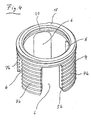
- eine teilgeschnittene perspektivische Ansicht eines Implantats mit einem ersten Hülsenteil und einem darin axial verfahrbar einliegenden zweiten Hülsenteil, wobei sich das zweite Hülsenteil in seiner eingefahrenen Position befindet,
- Fig. 2
- das Implantat von
Fig. 1 mit teilweise ausgefahrenem zweiten Hülsenteil, - Fig. 3
- eine perspektivische Ansicht' des ersten Hülsenteils,
- Fig. 4
- eine perspektivische Ansicht des ausfahrbaren zweiten Hülsenteils,
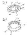
- Fig. 5
- eine zum Antrieb des ersten Hülsenteils dienende Mutter,
- Fig. 6
- eine an einem Hülsenteil fixierbare Stirnplatte,
- Fig. 7
- ein Werkzeug zur Handhabung des Implantats.
- Das in den Abbildungen gezeigte Implantat weist als Hauptbestandteile ein erstes Hülsenteil 1, ein zweites Hülsenteil 2 und eine Mutter 3 auf. Das Hülsenteil 2 ist mit einem sich im wesentlichen über seine gesamte Länge erstreckenden Außengewinde 4 versehen. Beide Hülsenteile 1,2 weisen axial verlaufende, in ihren im montierten Zustand in ihre einander zugewandten Stirnseite 5a,b ausmündende Fenster 6 auf. Die zwischen zwei benachbarten Fenstern stehen gebliebenen Umfangsabschnitte 7a,b liegen in den Fenstern 6 des jeweils anderen Hülsenteils 1,2 axial verschiebbar ein. Dabei ist das Spiel zwischen den Umfangsabschnitten 7a,b so bemessen, dass ein wackelfreier Sitz der dennoch beiden Hülsenteile ineinander und eine leichte Verschiebbarkeit gewährleistet ist. Die Hülsenteile 1,2 weisen etwa die gleiche Wandstärke und den gleichen Innendurchmesser auf, d.h. die Umfangsabschnitte 7b des zweiten Hülsenteils 2 stehen weder über den Außen- noch über den Innenumfang des Hülsenteils 1 hinaus. Die Axiallänge der Fenster 6 bzw. der Umfangsabschnitte 7a,b ist so bemessen, dass bei maximal eingefahrenem Hülsenteil 2 zwischen der Stirnseite 5a,b eines Umfangsabschnittes 7a,b und der Basis 8 eines Hülsenteils 1,2 ein Axialabstand 9 vorhanden ist.
- Zur Höhenverstellung bzw. zum Ein- und Ausfahren des Hülsenteils 2 dient die Mutter 3, welche beide Hülsenteile 1,2 umfasst. Sie ist mit dein ersten Hülsenteil axial fest und drehbar verbunden. Ihre die beiden Hülsenteile 1,2 umfassende Innenseite weist einen oberen, mit einem Innengewinde 10 versehenen Längsab'schnitt und einen sich daran anschließenden gewindefreien Längsabschnitt 13 auf. In diesen ist eine Ringnut 14 eingearbeitet. Die Mutter 3 ist so am Hülsenteil 1 positioniert, dass nur der gewindefreie Längsabschnitt 13 die Umfangsabschnitte 7a des Hülsenteils 1 umfasst und das Innengewinde 10 mit dem Außengewinde 4 des Hülsenteils 2 in Eingriff steht. Nahe der Stirnseite 5a eines Umfangsabschnittes 7a ist ein kreissegmentförmiger, sich über dessen gesamte Breite erstreckender Vorsprung 15 angeformt, der in die Ringnut 14 der Mutter eingreift. Die Mutter 3 kann sich dabei zwar am Hülsenteil 1 drehen, ist aber an diesem in beiden Axialrichtungen fixiert. Die den Freienden der Umfangsabschnitte 7b zugewandte Seite der Mutter 3 trägt einen koaxial zur Mittellängsachse 16 des Implantats verlaufenden Zahnring 17. Der Zahnring 17 ist einstückig an der.Mutter 3 angeformt, beispielsweise eingefräst. Er dient dazu, die Mutter 3 mit Hilfe eines weiter unten noch näher beschriebenen Werkzeugs in Drehung zu versetzen und dadurch das Hülsenteil 2 aus dem Hülsenteil 1 heraus oder in dieses hinein zu bewegen, also die Höhe des Implantats zu verstellen.
- Die den Freienden der Umfangsabschnitte 7a,b abgewandten Stirnseiten 18 tragen eine radial über den Umfang der Hülsenteile 1,2 hinaus stehende Stirnplatte 19. Die Stirnplatten 19 sind mit Hilfe einer Schnappverbindung lösbar an den Hülsenteilen 1,2 fixiert. Zu diesem Zwecke ist an der Innenseite der Hülsenteile 1,2 nähe deren Stirnseiten 18 eine Ringnut 20 vorhanden, in die an der den Stirnseiten 18a,b zugewandten Seite der Stirnplatte angeordnete Rastvorsprünge 23 eingreifen. Die Rastvorsprünge 23 sind an einer Schürze 24 angeformt, die eine zentrale Öffnung 21 in der Stirnplatte 19 umgrenzt. In den Rand 25 der Schürze 24 sind mehrere in Umfangsrichtung gleich verteilte Ausnehmungen 26 eingebracht. Die zwischen den Ausnehmungen 26 vorhandenen Umfangsabschnitte 27 tragen die Rastvorsprünge 23. Die Umfangsabschnitte 27 sind geringfügig radial nach innen elastisch auslenkbar, wodurch das Fixieren oder Entfernen der Stirnplatte 19 erleichtert ist. Auf den Außenseiten 28 der Stirnplatten 19 steht ein Zackenring 29 in Richtung der Längsachse 16 vor. Dieser dient zum Festkrallen des Implantats an einem Wirbelkörper.
- In den Umfangsabschnitten 7a sind zwei Durchbrechungen 30 vorhanden. Die Durchbrechungen 30 sowie die zentrale Öffnung 21 in den Stirnplatten 19 dienen zum Einfüllen von Knochenmaterial, Knochenzement oder dgl. In einem der Umfangsabschnitte 7a ist nahe der Mutter 3 eine radial ausgerichtete Gewindebohrung 33 vorhanden. Diese dient zur Fixierung des im folgenden beschriebenen Handhabungswerkzeuges.
- Wie aus
Fig. 7 ersichtlich ist, ist dieses im wesentlichen aus einem Stab 34 gebildet, dessen eines Ende einen Griff 35 und dessen anderes Ende einen Gewindeabschnitt 36 trägt. Der sich vom Gewindeabschnitt 36 weg erstreckende Bereich des Stabes 34 ist von einer Drehhülse 37 koaxial umfasst. Das dem Griff 35 zugewandte Ende der Drehhülse 37 trägt ein Rändelrad 38 und das gegenüberliegende Ende einen Zahnring 39. Dieser ist ähnlich wie bei der Mutter 3, durch eine fräsende Bearbeitung der Hülsenstirnseite hergestellt. Eine Axialbewegung der Hülse 37 in Richtung auf den Griff 35 ist durch einen Anschlagflansch 39 begrenzt. - Zur Höhenverstellung des Implantats, beispielsweise ausgehend von der in
Fig. 1 dargestellten Situation, wird das Handhabungswerkzeug'mit seinem Gewindeabschnitt 36 in die Gewindebohrung 33 eingedreht. Der Zahnring 39 steht dabei mit dem Zahnring 17 nach Art eines Kronenradgetriebes im Eingriff, d.h. die Achse des Zahnrings 39 verläuft im wesentlichen rechtwinklig zur Achse des Zahnrings 17. Das Rändelrad 38 liegt dabei am Anschlagflansch 29 an. - Nachdem das Implantat mit Hilfe des Handhabungswerkzeugs über eine Operationsöffnung in die Wirbelsäule eingesetzt wurde, wird zum Einstellen einer größeren Höhe des Implantats die Drehhülse 37 durch Betätigen des Rändelrades' 38 in Drehung versetzt. Wenn es sich bei dem Außengewinde 4 des Hülsenteils 2 und beim Innengewinde 10 der Mutter 3 um'Rechtsgewinde handelt, muss die Mutter 3 in Richtung des Pfeiles 40 und das Rändelrad in Richtung des Pfeiles 43 gedreht werden. Zum Lösen des Handhabungswerkzeuges vom Implantat wird dessen Gewindeabschnitt 36 durch Drehen des Griffs 35 aus der Gewindebohrung 33 entfernt. Da sich die Hülse 37 um den Stab 34 drehen kann, ist es nicht erforderlich, die Drehhülse während des Herausdrehens des Gewindeabschnittes 36 festzuhalten. Die Fixierung der einmal eingestellten Relativlage zwischen beiden Hülsenteilen 1,2 kann auf verschiedene Weise bewerkstelligt werden. Eine einfache Möglichkeit besteht darin, in die Gewindebohrung 33 eine etwa mit einer Spitze versehene Schraube (nicht dargestellt) einzudrehen.
-
- 1
- erstes Hülsenteil
- 2
- zweites Hülsenteil
- 3
- Mutter
- 4
- Außengewinde
- a,b
- Stirnseite
- 6
- Fenster
- 7a,b
- Umfangsabschnitt
(a = erstes Hülsenteil;
b = zweites Hülsenteil) - 8
- Basis
- 9
- Axialabstand
- 10
- Innengewinde
- 13
- Längsabschnitt
- 14
- Ringnut
- 15
- Vorsprung
- 16
- Mittellängsachse
- 17
- Zahnring
- 18
- Stirnseite
- 19
- Stirnplatte
- 20
- Ringnut
- 21
- Öffnung
- 23
- Rastvorsprung
- 24
- Schürze
- 25
- Rand
- 26
- Ausnehmung
- 27
- Umfangsabschnitt
- 28
- Außenseite
- 29
- Zackenring
- 30
- Durchbrechung
- 33
- Gewindebohrung
- 34
- Stab
- 35
- Griff
- 36
- Gewindeabschnitt
- 37
- Drehhülse
- 38
- Rändelrad
- 39
- Anschlagflansch
- 40
- Pfeil
- 43
- Pfeil
Claims (6)
- Höhenverstellbares Implantat zum Einsetzen zwischen Wirbelkörpern, mit einem ersten und einem zweiten Hülsenteil (1, 2), wobei das zweite Hülsenteil (2) ein Außengewinde (4) trägt, das mit einem Längsabschnitt im ersten Hülsenteil (1) drehfixiert und axial beweglich einliegt und an seinem aus dem ersten Hülsenteil (1) heraus ragenden Längsabschnitt von einer in das Außengewinde (4) eingreifenden Mutter (3) umfasst ist und die Mutter einen Zahnring (17) trägt, dadurch gekennzeichnet, daß
die Mutter (3) mit einem axial wirksamen Formschluss am ersten Hülsenteil (1) fixiert ist,
die Hülsenteile (1, 2) axial verlaufende, in ihren einander zugewandten Enden ausmündende Fenster (6) aufweisen, wobei die zwischen zwei benachbarten Fenstern angeordneten Umfangsabschnitte (7a, b) in den Fenstern (6) des jeweils anderen Hülsenteils (1, 2) axial verschiebbar einliegen,
die die beiden Hülsenteile (1, 2) umfassende Innenseite der Mutter einen oberen, mit einem Innengewinde (10) versehenen Längsabschitt und einen sich daran anschließenden gewindefrein Längsabschnitt (13) aufweist, in den eine Ringnut (14) eingearbeitet ist,
das erste Hülsenteil nahe seiner Stirnseite (5a) einen sich übe den Umfang des ersten Hülsenteils erstreckenden kreissegmentförmigen Vorsprung (15) aufweist, der in die Ringnut (14) der Mutter eingreift,
und wobei die Hülsenteile (1, 2) etwa die gleiche Wandstärke und den gleichen Innendurchmesser aufweisen. - Implantat nach Anspruch 1, dadurch gekennzeichnet, dass der Zahnring (17) an der dem ersten Hülsenteil (1) zugewandten Seite der Mutter (3) angeordnet ist.
- Implantat nach Anspruch 2, dadurch gekennzeichnet, dass im ersten Hülsenteil (1) wenigstens eine radial verlaufende Gewindebohrung (33) zur Fixierung eines die Mutter (3) antreibenden Werkzeugs vorhanden ist.
- Implantat nach einem der Ansprüche 1 bis 3, dadurch gekennzeichnet, dass an der zur Anlage an einem Wirbelkörper vorgesehenen Stirnseite (18) eines Hülsenteils (1, 2) eine als separates Teil ausgebildete Stirnplatte (19) lösbar fixiert ist.
- Implantat nach Anspruch 4, dadurch gekennzeichnet, dass die Stirnplatte (19) mit Hilfe einer Schnappverbindung am Hülsenteil (1, 2) fixiert ist.
- Implantat nach Anspruch 5, gekennzeichnet durch eine nahe der Stirnseite (18) angeordnete Ringnut (20) in der Innenwandung des Hülsenteils (1, 2), in die an der Stirnplatte (19) angeformte Rastnasen eingreifen.
Priority Applications (3)
| Application Number | Priority Date | Filing Date | Title |
|---|---|---|---|
| DE202004021288U DE202004021288U1 (de) | 2003-05-14 | 2004-05-11 | Höhenverstellbares Implantat zum Einsetzen zwischen Wirbelkörpern und Handhabungswerkzeug |
| DE202004021290U DE202004021290U1 (de) | 2003-05-14 | 2004-05-11 | Höhenverstellbares Implantat zum Einsetzen zwischen Wirbelkörpern und Handhabungswerkzeug |
| DE202004021289U DE202004021289U1 (de) | 2003-05-14 | 2004-05-11 | Höhenverstellbares Implantat zum Einsetzen zwischen Wirbelkörpern und Handhabungswerkzeug |
Applications Claiming Priority (3)
| Application Number | Priority Date | Filing Date | Title |
|---|---|---|---|
| DE10321534 | 2003-05-14 | ||
| DE10321534 | 2003-05-14 | ||
| PCT/EP2004/005046 WO2004100837A1 (de) | 2003-05-14 | 2004-05-11 | Höhenverstellbares implantat zum einsetzen zwischen wirbelkörpern und handhabungswerkzeug |
Publications (3)
| Publication Number | Publication Date |
|---|---|
| EP1501453A1 EP1501453A1 (de) | 2005-02-02 |
| EP1501453B1 EP1501453B1 (de) | 2005-12-07 |
| EP1501453B2 true EP1501453B2 (de) | 2010-06-30 |
Family
ID=33440774
Family Applications (1)
| Application Number | Title | Priority Date | Filing Date |
|---|---|---|---|
| EP04732110A Expired - Lifetime EP1501453B2 (de) | 2003-05-14 | 2004-05-11 | Höhenverstellbares implantat zum einsetzen zwischen wirbelkörpern und handhabungswerkzeug |
Country Status (7)
| Country | Link |
|---|---|
| US (1) | US8568482B2 (de) |
| EP (1) | EP1501453B2 (de) |
| JP (1) | JP4410254B2 (de) |
| AT (1) | ATE311836T1 (de) |
| DE (4) | DE202004021289U1 (de) |
| ES (1) | ES2249757T5 (de) |
| WO (1) | WO2004100837A1 (de) |
Families Citing this family (71)
| Publication number | Priority date | Publication date | Assignee | Title |
|---|---|---|---|---|
| US7918876B2 (en) * | 2003-03-24 | 2011-04-05 | Theken Spine, Llc | Spinal implant adjustment device |
| ES2300566T3 (es) * | 2003-04-28 | 2008-06-16 | Synthes Gmbh | Implante intervertebral. |
| DE202004021289U1 (de) | 2003-05-14 | 2007-06-06 | Kraus, Kilian | Höhenverstellbares Implantat zum Einsetzen zwischen Wirbelkörpern und Handhabungswerkzeug |
| DE10357926B3 (de) | 2003-12-11 | 2005-09-01 | Deltacor Gmbh | Längenverstellbares Wirbelsäulen-Implantat |
| US7674296B2 (en) * | 2005-04-21 | 2010-03-09 | Globus Medical, Inc. | Expandable vertebral prosthesis |
| US8308802B2 (en) | 2010-01-21 | 2012-11-13 | Globus Medical, Inc. | Expandable vertebral prosthesis |
| US7811327B2 (en) | 2005-04-21 | 2010-10-12 | Globus Medical Inc. | Expandable vertebral prosthesis |
| DE102005061932A1 (de) * | 2005-12-23 | 2007-07-05 | Biedermann Motech Gmbh | Mehrwandiger Platzhalter |
| US7879096B2 (en) | 2006-04-27 | 2011-02-01 | Warsaw Orthopedic, Inc. | Centrally driven expandable implant |
| US7758648B2 (en) | 2006-04-27 | 2010-07-20 | Warsaw Orthopedic, Inc. | Stabilized, adjustable expandable implant and method |
| US7981157B2 (en) | 2006-04-27 | 2011-07-19 | Warsaw Orthopedic, Inc. | Self-contained expandable implant and method |
| US7914581B2 (en) | 2006-04-27 | 2011-03-29 | Warsaw Orthopedic, Inc. | Expandable implant, instrument, and method |
| US7794501B2 (en) | 2006-04-27 | 2010-09-14 | Wasaw Orthopedic, Inc. | Expandable intervertebral spacers and methods of use |
| US7708779B2 (en) | 2006-05-01 | 2010-05-04 | Warsaw Orthopedic, Inc. | Expandable intervertebral spacers and methods of use |
| US8328871B2 (en) | 2006-11-09 | 2012-12-11 | Warsaw Orthopedic, Inc. | Expanding vertebral body implant |
| US8062366B2 (en) | 2007-01-08 | 2011-11-22 | Warsaw Orthopedic, Inc. | Ratcheting expandable corpectomy/vertebrectomy cage |
| MX2009007197A (es) * | 2007-03-07 | 2009-10-13 | Ulrich Gmbh & Co Kg | Implante intervertebral con componente elastico. |
| AU2008224951A1 (en) | 2007-03-13 | 2008-09-18 | Synthes Gmbh | Adjustable intervertebral implant |
| US8591587B2 (en) | 2007-10-30 | 2013-11-26 | Aesculap Implant Systems, Llc | Vertebral body replacement device and method for use to maintain a space between two vertebral bodies within a spine |
| DE102007052042A1 (de) * | 2007-10-30 | 2009-05-14 | Kilian Kraus | Höhenverstellbares Wirbelsäulenimplantat |
| US8142441B2 (en) | 2008-10-16 | 2012-03-27 | Aesculap Implant Systems, Llc | Surgical instrument and method of use for inserting an implant between two bones |
| US8241363B2 (en) * | 2007-12-19 | 2012-08-14 | Depuy Spine, Inc. | Expandable corpectomy spinal fusion cage |
| US8241294B2 (en) * | 2007-12-19 | 2012-08-14 | Depuy Spine, Inc. | Instruments for expandable corpectomy spinal fusion cage |
| US8425608B2 (en) | 2008-01-18 | 2013-04-23 | Warsaw Orthopedic, Inc. | Lordotic expanding vertebral body spacer |
| US9700431B2 (en) * | 2008-08-13 | 2017-07-11 | Smed-Ta/Td, Llc | Orthopaedic implant with porous structural member |
| US10842645B2 (en) | 2008-08-13 | 2020-11-24 | Smed-Ta/Td, Llc | Orthopaedic implant with porous structural member |
| KR101496197B1 (ko) | 2008-09-04 | 2015-02-26 | 신세스 게엠바하 | 조절가능한 추간 임플란트 |
| JP2012502702A (ja) * | 2008-09-19 | 2012-02-02 | ウルリッヒ ゲーエムベーハー ウント コンパニ カーゲー | 脊柱の椎体の間に差し込むためのインプラント |
| US8252054B2 (en) | 2009-01-14 | 2012-08-28 | Stout Medical Group, L.P. | Expandable support device and method of use |
| US9687357B2 (en) * | 2009-03-12 | 2017-06-27 | Nuvasive, Inc. | Vertebral body replacement |
| US9387090B2 (en) * | 2009-03-12 | 2016-07-12 | Nuvasive, Inc. | Vertebral body replacement |
| US8292963B2 (en) | 2009-04-23 | 2012-10-23 | Warsaw Orthopedic, Inc. | Expandable implant for supporting skeletal structures |
| US8876905B2 (en) * | 2009-04-29 | 2014-11-04 | DePuy Synthes Products, LLC | Minimally invasive corpectomy cage and instrument |
| EP2349112B1 (de) * | 2009-06-17 | 2014-07-23 | Ulrich GmbH & Co. KG | Implantat |
| US8202321B2 (en) | 2009-06-17 | 2012-06-19 | Ulrich Gmbh & Co. Kg | Implant |
| US8211178B2 (en) | 2009-06-18 | 2012-07-03 | Warsaw Orthopedic | Intervertebral implant with a pivoting end cap |
| WO2011059498A1 (en) | 2009-11-11 | 2011-05-19 | Nuvasive, Inc. | Surgical access system and related methods |
| EP2547292B1 (de) | 2010-03-16 | 2019-04-24 | Pinnacle Spine Group, LLC | Zwischenwirbelimplantate sowie implantateinsatzsysteme |
| US11426287B2 (en) * | 2010-04-12 | 2022-08-30 | Globus Medical Inc. | Expandable vertebral implant |
| US9579211B2 (en) | 2010-04-12 | 2017-02-28 | Globus Medical, Inc. | Expandable vertebral implant |
| US8282683B2 (en) | 2010-04-12 | 2012-10-09 | Globus Medical, Inc. | Expandable vertebral implant |
| US8870880B2 (en) | 2010-04-12 | 2014-10-28 | Globus Medical, Inc. | Angling inserter tool for expandable vertebral implant |
| US9271842B2 (en) * | 2010-04-12 | 2016-03-01 | Globus Medical, Inc. | Expandable trial assembly for expandable vertebral implant |
| US8591585B2 (en) * | 2010-04-12 | 2013-11-26 | Globus Medical, Inc. | Expandable vertebral implant |
| US9301850B2 (en) | 2010-04-12 | 2016-04-05 | Globus Medical, Inc. | Expandable vertebral implant |
| DE102010018379B4 (de) * | 2010-04-26 | 2018-10-18 | Peter Metz-Stavenhagen | Wirbelsäulenimplantat und Werkzeug hierfür |
| SG187593A1 (en) * | 2010-07-29 | 2013-03-28 | Mayo Foundation | Acetabular cup prosthesis |
| US8740980B2 (en) | 2011-01-27 | 2014-06-03 | Warsaw Orthopedic, Inc. | Expandable medical implant |
| DE102011018692B4 (de) | 2011-04-26 | 2016-06-23 | Peter Metz-Stavenhagen | Wirbelsäulenimplantat, Werkzeug hierfür und Verfahren zur Distraktion des Wirbelsäulenimplantats |
| WO2013000138A1 (zh) * | 2011-06-29 | 2013-01-03 | 西安交通大学 | 一种可调式人工颈椎及椎间连接复合体 |
| US9380932B1 (en) | 2011-11-02 | 2016-07-05 | Pinnacle Spine Group, Llc | Retractor devices for minimally invasive access to the spine |
| WO2014159739A1 (en) | 2013-03-14 | 2014-10-02 | Pinnacle Spine Group, Llc | Interbody implants and graft delivery systems |
| US9211193B2 (en) | 2013-08-30 | 2015-12-15 | Aesculap Implant Systems, Llc | Prosthesis, system and method |
| US9808354B2 (en) | 2014-01-17 | 2017-11-07 | Stryker European Holdings I, Llc | Implant insertion tool |
| TWM501578U (zh) * | 2015-02-13 | 2015-05-21 | Au Optronics Corp | 顯示裝置 |
| US9775719B2 (en) | 2015-03-23 | 2017-10-03 | Musc Foundation For Research Development | Expandable vertebral body replacement device and method |
| US9889018B2 (en) | 2015-03-23 | 2018-02-13 | Musc Foundation For Research Development | Expandable vertebral body replacement device and method |
| US9844446B2 (en) * | 2016-05-05 | 2017-12-19 | Globus Medical, Inc. | Expandable vertebral implant |
| US10842651B2 (en) * | 2016-06-10 | 2020-11-24 | Globus Medical, Inc. | Vertebral implants and attachment assemblies |
| LU93170B1 (en) * | 2016-08-11 | 2018-03-28 | Ulrich Gmbh & Co Kg | Attachment of tracking elements to surgical instruments |
| AU2017363425B2 (en) * | 2016-11-28 | 2023-06-22 | Musc Foundation For Research Development | Expandable vertebral body replacement device and method |
| KR101994119B1 (ko) * | 2018-08-24 | 2019-07-02 | 주식회사 올뎃덴탈 | 임플란트용 교합측정기 |
| US11622864B2 (en) | 2019-06-28 | 2023-04-11 | Innovasis, Inc. | Expandable intervertebral implant |
| AU2021226916A1 (en) | 2020-02-24 | 2022-10-06 | Musc Foundation For Research Development | Expandable vertebral body replacement device and method |
| CN111281622B (zh) * | 2020-03-26 | 2025-02-11 | 迪恩医疗科技有限公司 | 椎体置换装置 |
| US11376052B2 (en) * | 2020-09-02 | 2022-07-05 | Curiteva, Inc | Expandable laminoplasty device |
| DE102020007873A1 (de) | 2020-12-22 | 2022-06-23 | Taurus Gmbh & Co. Kg | Höhenverstellbares implantat |
| US12589006B2 (en) | 2021-10-08 | 2026-03-31 | Seaspine Orthopedics Corporation | Expandable vertebral implant and method |
| WO2024112602A1 (en) | 2022-11-22 | 2024-05-30 | Alphatec Spine, Inc | Vertebral body replacement and insertion device |
| EP4473946B1 (de) * | 2023-06-07 | 2026-03-11 | Biedermann Technologies GmbH & Co. KG | Implantat zur verbindung zwischen wirbeln und implantatkit |
| US12465498B2 (en) | 2023-06-27 | 2025-11-11 | Bala Sundararajan | Expandable intervertebral interbody implants |
Citations (3)
| Publication number | Priority date | Publication date | Assignee | Title |
|---|---|---|---|---|
| JPH02261446A (ja) † | 1989-04-03 | 1990-10-24 | Kawasaki Steel Corp | 人工椎体 |
| USD450122S1 (en) † | 2000-01-03 | 2001-11-06 | Gary K. Michelson | End cap for a spinal implant |
| US20020082695A1 (en) † | 2000-12-27 | 2002-06-27 | Ulrich Gmbh & Co. Kg | Vertebral implant and setting tool therefor |
Family Cites Families (186)
| Publication number | Priority date | Publication date | Assignee | Title |
|---|---|---|---|---|
| US1238863A (en) * | 1917-03-14 | 1917-09-04 | Ashland Products Co | Jack. |
| US1486723A (en) * | 1921-07-12 | 1924-03-11 | Maurice F Bernson | Jack |
| US1645570A (en) | 1924-06-12 | 1927-10-18 | Anderson Nils Alfred | Wrench |
| US1896715A (en) * | 1929-12-12 | 1933-02-07 | Carlo D Martinetti | Automobile lifting jack |
| US2702453A (en) * | 1949-07-09 | 1955-02-22 | Mercier Dev Corp | Equipressure power generating plant and method of operating same |
| DE2340546A1 (de) | 1973-08-10 | 1975-02-27 | Pfaudler Werke Ag | Metallisches implantat und verfahren zu seiner herstellung |
| DE3023942C2 (de) | 1980-06-26 | 1985-05-15 | Waldemar Link (Gmbh & Co), 2000 Hamburg | Implantat zum Einsetzen zwischen Wirbelkörper der Wirbelsäule und Zange zum Einsetzen und Distrahieren desselben |
| US4502160A (en) | 1983-10-27 | 1985-03-05 | Dow Corning Wright | Adjustable length prosthetic joint implant |
| FR2575059B1 (fr) * | 1984-12-21 | 1988-11-10 | Daher Youssef | Dispositif d'etaiement utilisable dans une prothese vertebrale |
| DE8711992U1 (de) | 1987-09-04 | 1987-10-15 | Aesculap-Werke Ag Vormals Jetter & Scheerer, 7200 Tuttlingen | Implantat zum Einsetzen zwischen Wirbelkörper der Wirbelsäule |
| US6923810B1 (en) | 1988-06-13 | 2005-08-02 | Gary Karlin Michelson | Frusto-conical interbody spinal fusion implants |
| US5772661A (en) | 1988-06-13 | 1998-06-30 | Michelson; Gary Karlin | Methods and instrumentation for the surgical correction of human thoracic and lumbar spinal disease from the antero-lateral aspect of the spine |
| US7452359B1 (en) | 1988-06-13 | 2008-11-18 | Warsaw Orthopedic, Inc. | Apparatus for inserting spinal implants |
| US4961740B1 (en) | 1988-10-17 | 1997-01-14 | Surgical Dynamics Inc | V-thread fusion cage and method of fusing a bone joint |
| US4932975A (en) * | 1989-10-16 | 1990-06-12 | Vanderbilt University | Vertebral prosthesis |
| US5055104A (en) | 1989-11-06 | 1991-10-08 | Surgical Dynamics, Inc. | Surgically implanting threaded fusion cages between adjacent low-back vertebrae by an anterior approach |
| US5236460A (en) | 1990-02-12 | 1993-08-17 | Midas Rex Pneumatic Tools, Inc. | Vertebral body prosthesis |
| FR2666221B1 (fr) | 1990-09-04 | 1997-11-21 | Gilles Missenard | Module prothetique de croissance, extensible. |
| DK0637944T3 (da) | 1992-04-28 | 1998-12-28 | Donald R Huene | Absorberbar knogleskrue og anordning til anbringelse af en sådan |
| US5246458A (en) | 1992-10-07 | 1993-09-21 | Graham Donald V | Artificial disk |
| CA2551185C (en) | 1994-03-28 | 2007-10-30 | Sdgi Holdings, Inc. | Apparatus and method for anterior spinal stabilization |
| DE4423257C2 (de) | 1994-07-02 | 2001-07-12 | Ulrich Heinrich | Implantat zum Einsetzen zwischen Wirbelkörper der Wirbelsäule als Platzhalter |
| US5980522A (en) | 1994-07-22 | 1999-11-09 | Koros; Tibor | Expandable spinal implants |
| US6478795B1 (en) | 1994-08-29 | 2002-11-12 | Sofamor S.N.C. | Torque limiting clamping plug for osteosynthesis instrumentation |
| US5885299A (en) * | 1994-09-15 | 1999-03-23 | Surgical Dynamics, Inc. | Apparatus and method for implant insertion |
| US6344057B1 (en) * | 1994-11-22 | 2002-02-05 | Sdgi Holdings, Inc. | Adjustable vertebral body replacement |
| ES2238684T3 (es) | 1994-12-09 | 2005-09-01 | Sdgi Holdings, Inc. | Substitucion de cuerpo vertebral ajustable. |
| TW316844B (de) | 1994-12-09 | 1997-10-01 | Sofamor Danek Group Inc | |
| CA2164922C (en) | 1994-12-12 | 2006-05-23 | Paul W. Pavlov | Conically-shaped fusion cage and method of implantation |
| US5665122A (en) * | 1995-01-31 | 1997-09-09 | Kambin; Parviz | Expandable intervertebral cage and surgical method |
| FR2730158B1 (fr) * | 1995-02-06 | 1999-11-26 | Jbs Sa | Dispositif de maintien d'un ecartement normal entre les vertebres et destine au remplacement de vertebres manquantes |
| DE19509317B4 (de) | 1995-03-15 | 2006-08-10 | Heinrich Ulrich | Implantat zum Einsetzen zwischen Wirbelkörper der Wirbelsäule als Platzhalter |
| US5782919A (en) | 1995-03-27 | 1998-07-21 | Sdgi Holdings, Inc. | Interbody fusion device and method for restoration of normal spinal anatomy |
| US6206922B1 (en) | 1995-03-27 | 2001-03-27 | Sdgi Holdings, Inc. | Methods and instruments for interbody fusion |
| US5575790A (en) | 1995-03-28 | 1996-11-19 | Rensselaer Polytechnic Institute | Shape memory alloy internal linear actuator for use in orthopedic correction |
| DE19519101B4 (de) | 1995-05-24 | 2009-04-23 | Harms, Jürgen, Prof. Dr. | Höhenverstellbarer Wirbelkörperersatz |
| US5702449A (en) | 1995-06-07 | 1997-12-30 | Danek Medical, Inc. | Reinforced porous spinal implants |
| JP3621424B2 (ja) * | 1995-10-20 | 2005-02-16 | ジンテーズ アクチエンゲゼルシャフト クール | ケージと回転体を有する椎間インプラント |
| DE19622827B4 (de) | 1996-06-07 | 2009-04-23 | Ulrich, Heinrich | Implantat zum Einsetzen zwischen Wirbelkörper als Platzhalter |
| US5702455A (en) | 1996-07-03 | 1997-12-30 | Saggar; Rahul | Expandable prosthesis for spinal fusion |
| US5895426A (en) | 1996-09-06 | 1999-04-20 | Osteotech, Inc. | Fusion implant device and method of use |
| FR2753368B1 (fr) | 1996-09-13 | 1999-01-08 | Chauvin Jean Luc | Cage d'osteosynthese expansive |
| DE29616778U1 (de) | 1996-09-26 | 1998-01-29 | Howmedica GmbH, 24232 Schönkirchen | Wirbelkörperplatzhalter |
| US6190414B1 (en) * | 1996-10-31 | 2001-02-20 | Surgical Dynamics Inc. | Apparatus for fusion of adjacent bone structures |
| US6068630A (en) * | 1997-01-02 | 2000-05-30 | St. Francis Medical Technologies, Inc. | Spine distraction implant |
| US7306628B2 (en) * | 2002-10-29 | 2007-12-11 | St. Francis Medical Technologies | Interspinous process apparatus and method with a selectably expandable spacer |
| US6156038A (en) | 1997-01-02 | 2000-12-05 | St. Francis Medical Technologies, Inc. | Spine distraction implant and method |
| US7201751B2 (en) * | 1997-01-02 | 2007-04-10 | St. Francis Medical Technologies, Inc. | Supplemental spine fixation device |
| US20080027552A1 (en) * | 1997-01-02 | 2008-01-31 | Zucherman James F | Spine distraction implant and method |
| US5836948A (en) | 1997-01-02 | 1998-11-17 | Saint Francis Medical Technologies, Llc | Spine distraction implant and method |
| US20080215058A1 (en) * | 1997-01-02 | 2008-09-04 | Zucherman James F | Spine distraction implant and method |
| US20080071378A1 (en) * | 1997-01-02 | 2008-03-20 | Zucherman James F | Spine distraction implant and method |
| IL128261A0 (en) | 1999-01-27 | 1999-11-30 | Disc O Tech Medical Tech Ltd | Expandable element |
| US5916267A (en) | 1997-04-07 | 1999-06-29 | Arthit Sitiso | Anterior spinal implant system for vertebral body prosthesis |
| EP0975288B1 (de) * | 1997-04-15 | 2002-10-02 | Synthes AG Chur | Teleskopierende wirbelprothese |
| WO1998048738A1 (fr) * | 1997-04-25 | 1998-11-05 | Stryker France S.A. | Implants intersomatiques en deux parties |
| US6641614B1 (en) * | 1997-05-01 | 2003-11-04 | Spinal Concepts, Inc. | Multi-variable-height fusion device |
| US6045579A (en) | 1997-05-01 | 2000-04-04 | Spinal Concepts, Inc. | Adjustable height fusion device |
| FR2762778B1 (fr) * | 1997-05-02 | 1999-07-16 | Stryker France Sa | Implant notamment pour le remplacement d'un corps vertebral en chirurgie du rachis |
| US6783526B1 (en) | 1997-05-15 | 2004-08-31 | Howmedica Osteonics Corp. | Transverse rod connector clip |
| US6042582A (en) * | 1997-05-20 | 2000-03-28 | Ray; Charles D. | Instrumentation and method for facilitating insertion of spinal implant |
| US6033438A (en) | 1997-06-03 | 2000-03-07 | Sdgi Holdings, Inc. | Open intervertebral spacer |
| BE1011217A3 (nl) | 1997-06-16 | 1999-06-01 | Vanderschot Paul | Intercorporeel implantaat voor een operatieve of endoscopische anterieure fusie na corporectomie ter hoogte van de thoraco-lumbale wervelzuil. |
| US5951553A (en) | 1997-07-14 | 1999-09-14 | Sdgi Holdings, Inc. | Methods and apparatus for fusionless treatment of spinal deformities |
| US6287308B1 (en) | 1997-07-14 | 2001-09-11 | Sdgi Holdings, Inc. | Methods and apparatus for fusionless treatment of spinal deformities |
| US5904719A (en) * | 1997-07-24 | 1999-05-18 | Techsys Medical, Llc | Interbody fusion device having partial circular section cross-sectional segments |
| DE59710823D1 (de) | 1997-08-06 | 2003-11-06 | Synthes Ag | Spreizbares zwischenwirbelimplantat |
| US6086595A (en) | 1997-08-29 | 2000-07-11 | Sulzer Spine-Tech Inc. | Apparatus and method for spinal stabilization |
| US6004326A (en) | 1997-09-10 | 1999-12-21 | United States Surgical | Method and instrumentation for implant insertion |
| EP0904751B1 (de) * | 1997-09-30 | 2003-08-20 | Centerpulse Orthopedics Ltd. | Rohrförmiger Stützkörper zum Überbrücken zweier Wirbel |
| ES2226186T3 (es) | 1997-11-29 | 2005-03-16 | Surgicraft Limited | Implante quirurgico y tornillo de fijacion quirurgico. |
| US20010001129A1 (en) | 1997-12-10 | 2001-05-10 | Mckay William F. | Osteogenic fusion device |
| FR2772594B1 (fr) | 1997-12-19 | 2000-05-05 | Henry Graf | Prothese discale partielle posterieure |
| US6086613A (en) | 1997-12-23 | 2000-07-11 | Depuy Acromed, Inc. | Spacer assembly for use in spinal surgeries |
| FR2774280B1 (fr) | 1998-01-30 | 2000-07-28 | Dimso Sa | Implant pour remplacer une vertebre |
| DE19804765C2 (de) * | 1998-02-06 | 2000-09-28 | Biedermann Motech Gmbh | Platzhalter mit einstellbarer axialer Länge |
| DE19816782A1 (de) | 1998-04-16 | 1999-10-28 | Ulrich Gmbh & Co Kg | Implantat zum Einsetzen zwischen Wirbelkörper der Wirbelsäule |
| AU748746B2 (en) | 1998-07-22 | 2002-06-13 | Spinal Dynamics Corporation | Threaded cylindrical multidiscoid single or multiple array disc prosthesis |
| FR2782632B1 (fr) | 1998-08-28 | 2000-12-29 | Materiel Orthopedique En Abreg | Cage de fusion intersomatique expansible |
| DE19841252B4 (de) | 1998-09-09 | 2006-01-26 | Aesculap Ag & Co. Kg | Einsetzinstrument für eine Knochenschraube |
| ATE268579T1 (de) * | 1998-10-15 | 2004-06-15 | Synthes Ag | Teleskopierende wirbelprothese |
| FR2787015B1 (fr) | 1998-12-11 | 2001-04-27 | Dimso Sa | Prothese de disque intervertebral a corps compressible |
| BR9805340B1 (pt) | 1998-12-14 | 2009-01-13 | inserto de expansço variÁvel para estabilizaÇço de coluna vertebral. | |
| CA2361068A1 (en) * | 1999-02-04 | 2000-08-10 | Sdgi Holdings, Inc. | Improved interbody fusion device with anti-rotation features |
| FR2789886B1 (fr) | 1999-02-18 | 2001-07-06 | Dimso Sa | Dispositif de distraction/contraction pour systeme d'osteosynthese rachidienne |
| GB9904373D0 (en) | 1999-02-25 | 1999-04-21 | Microsulis Plc | Radiation applicator |
| US6113638A (en) | 1999-02-26 | 2000-09-05 | Williams; Lytton A. | Method and apparatus for intervertebral implant anchorage |
| US6267763B1 (en) | 1999-03-31 | 2001-07-31 | Surgical Dynamics, Inc. | Method and apparatus for spinal implant insertion |
| US6520991B2 (en) * | 1999-05-11 | 2003-02-18 | Donald R. Huene | Expandable implant for inter-vertebral stabilization, and a method of stabilizing vertebrae |
| US6214050B1 (en) * | 1999-05-11 | 2001-04-10 | Donald R. Huene | Expandable implant for inter-bone stabilization and adapted to extrude osteogenic material, and a method of stabilizing bones while extruding osteogenic material |
| US7331994B2 (en) * | 1999-05-17 | 2008-02-19 | Vanderbilt University | Intervertebral disc replacement prosthesis |
| JP2003501142A (ja) | 1999-06-04 | 2003-01-14 | エスディージーアイ・ホールディングス・インコーポレーテッド | 椎間板用人工移植部材 |
| US6419705B1 (en) | 1999-06-23 | 2002-07-16 | Sulzer Spine-Tech Inc. | Expandable fusion device and method |
| US6454806B1 (en) | 1999-07-26 | 2002-09-24 | Advanced Prosthetic Technologies, Inc. | Spinal surgical prosthesis |
| WO2002009626A1 (en) | 1999-07-26 | 2002-02-07 | Advanced Prosthetic Technologies, Inc. | Improved spinal surgical prosthesis |
| WO2001013807A2 (en) * | 1999-08-26 | 2001-03-01 | Sdgi Holdings, Inc. | Devices and methods for implanting fusion cages |
| ES2224695T3 (es) | 1999-08-27 | 2005-03-01 | Synthes Ag Chur | Implante intervertebral. |
| US6866682B1 (en) * | 1999-09-02 | 2005-03-15 | Stryker Spine | Distractable corpectomy device |
| US6315975B1 (en) | 1999-09-10 | 2001-11-13 | Rhodia Inc. | Suspension system using fumed silica |
| US6395034B1 (en) * | 1999-11-24 | 2002-05-28 | Loubert Suddaby | Intervertebral disc prosthesis |
| ES2269092T3 (es) * | 1999-12-15 | 2007-04-01 | Zimmer Gmbh | Implante intervertebral. |
| KR200188511Y1 (ko) | 2000-01-06 | 2000-07-15 | 구자교 | 척추용 보철 플러그 |
| WO2001050968A1 (de) * | 2000-01-13 | 2001-07-19 | Synthes Ag Chur | Vorrichtung zum lösbaren festklemmen eines längsträgers innerhalb eines chirurgischen implantates |
| EP1645248B8 (de) * | 2000-02-04 | 2010-06-16 | Warsaw Orthopedic, Inc. | Ausdehnbares interspinales Fusionsimplantat mit schwenkbarem Blocker |
| US6814756B1 (en) * | 2000-02-04 | 2004-11-09 | Gary K. Michelson | Expandable threaded arcuate interbody spinal fusion implant with lordotic configuration during insertion |
| US6899716B2 (en) | 2000-02-16 | 2005-05-31 | Trans1, Inc. | Method and apparatus for spinal augmentation |
| US7776068B2 (en) | 2003-10-23 | 2010-08-17 | Trans1 Inc. | Spinal motion preservation assemblies |
| FR2805451B1 (fr) | 2000-02-29 | 2002-04-19 | Arnaud Andre Soubeiran | Dispositif perfectionne pour deplacer deux corps l'un par rapport a l'autre, en particulier pour la realisation de systemes implantables dans le corps humain |
| US7182781B1 (en) * | 2000-03-02 | 2007-02-27 | Regeneration Technologies, Inc. | Cervical tapered dowel |
| US6296665B1 (en) | 2000-03-20 | 2001-10-02 | Electro-Biology, Inc. | Method and apparatus for spinal fixation |
| AR027685A1 (es) | 2000-03-22 | 2003-04-09 | Synthes Ag | Forma de tejido y metodo para realizarlo |
| PT1267755E (pt) * | 2000-03-31 | 2006-09-29 | Konigsee Implantate Inst Osteo | Implante para corpo de vertebra ajustavel em altura |
| US6554265B2 (en) * | 2000-04-11 | 2003-04-29 | Randall C. Andronica | Universal workholding V fixture convertable to other applications |
| US6821298B1 (en) | 2000-04-18 | 2004-11-23 | Roger P. Jackson | Anterior expandable spinal fusion cage system |
| US6808537B2 (en) * | 2000-07-07 | 2004-10-26 | Gary Karlin Michelson | Expandable implant with interlocking walls |
| US6626905B1 (en) * | 2000-08-02 | 2003-09-30 | Sulzer Spine-Tech Inc. | Posterior oblique lumbar arthrodesis |
| CA2426932A1 (en) | 2000-10-25 | 2002-06-20 | Sdgi Holdings, Inc. | Vertically expanding intervertebral body fusion device |
| US6544265B2 (en) * | 2000-11-08 | 2003-04-08 | The Cleveland Clinic Foundation | Apparatus for implantation into bone related applications |
| US6551319B2 (en) * | 2000-11-08 | 2003-04-22 | The Cleveland Clinic Foundation | Apparatus for implantation into bone |
| US6454807B1 (en) | 2000-11-30 | 2002-09-24 | Roger P. Jackson | Articulated expandable spinal fusion cage system |
| US6443989B1 (en) | 2000-12-04 | 2002-09-03 | Roger P. Jackson | Posterior expandable fusion cage |
| US6773460B2 (en) | 2000-12-05 | 2004-08-10 | Roger P. Jackson | Anterior variable expandable fusion cage |
| FR2817462B1 (fr) * | 2000-12-05 | 2003-08-08 | Stryker Spine Sa | Implant intersomatique rachidien distractable in situ comportant des points de passage dur |
| US6810162B2 (en) | 2000-12-20 | 2004-10-26 | Shipley Company, L.L.C. | Optical switch assembly with flex plate and method for making |
| FR2819711B1 (fr) * | 2001-01-23 | 2003-08-01 | Stryker Spine Sa | Systeme de reglage en position pour instrument de chirurgie rachidienne |
| US6899734B2 (en) * | 2001-03-23 | 2005-05-31 | Howmedica Osteonics Corp. | Modular implant for fusing adjacent bone structure |
| US7128760B2 (en) | 2001-03-27 | 2006-10-31 | Warsaw Orthopedic, Inc. | Radially expanding interbody spinal fusion implants, instrumentation, and methods of insertion |
| DE10116412C1 (de) | 2001-04-02 | 2003-01-16 | Ulrich Gmbh & Co Kg | Implantat zum Einsetzen zwischen Wirbelkörper der Wirbelsäule |
| DE20109599U1 (de) * | 2001-06-08 | 2001-08-23 | Aesculap AG & Co. KG, 78532 Tuttlingen | Wirbelersatzkörper |
| US6511484B2 (en) * | 2001-06-29 | 2003-01-28 | Depuy Acromed, Inc. | Tool and system for aligning and applying fastener to implanted anchor |
| US7018412B2 (en) * | 2001-08-20 | 2006-03-28 | Ebi, L.P. | Allograft spinal implant |
| TW545211U (en) * | 2001-08-29 | 2003-08-01 | Jung-Chiuan Ye | Device for fastening spine |
| US6896512B2 (en) * | 2001-09-19 | 2005-05-24 | Aztec Machinery Company | Radiator element |
| US6648917B2 (en) * | 2001-10-17 | 2003-11-18 | Medicinelodge, Inc. | Adjustable bone fusion implant and method |
| US6451057B1 (en) | 2001-10-29 | 2002-09-17 | Chen Po-Quang | Spinal plate element adjusting device having a threaded engagement |
| US7025787B2 (en) * | 2001-11-26 | 2006-04-11 | Sdgi Holdings, Inc. | Implantable joint prosthesis and associated instrumentation |
| US6979353B2 (en) | 2001-12-03 | 2005-12-27 | Howmedica Osteonics Corp. | Apparatus for fusing adjacent bone structures |
| US6923830B2 (en) | 2002-02-02 | 2005-08-02 | Gary K. Michelson | Spinal fusion implant having deployable bone engaging projections |
| DE10210214B4 (de) | 2002-03-02 | 2005-01-05 | Bernd Schäfer | Distrahierbares Wirbelsäulenimplantat und Werkzeug zum Distrahieren |
| US6808538B2 (en) | 2002-03-15 | 2004-10-26 | Stryker Spine | Vertebral body spacer having variable wedged endplates |
| US6758862B2 (en) | 2002-03-21 | 2004-07-06 | Sdgi Holdings, Inc. | Vertebral body and disc space replacement devices |
| US7309358B2 (en) | 2002-03-21 | 2007-12-18 | Warsaw Orthopedic, Inc. | Vertebral body and disc space replacement devices |
| US6991653B2 (en) | 2002-03-21 | 2006-01-31 | Sdgi Holdings, Inc. | Vertebral body and disc space replacement devices |
| US6779353B2 (en) | 2002-03-29 | 2004-08-24 | General Electric Company | Sealed system multiple speed compressor and fan control |
| US6766798B2 (en) | 2002-04-02 | 2004-07-27 | Schuyler Herres | Supplemental air directing extension frame for a fireplace |
| US6783547B2 (en) | 2002-04-05 | 2004-08-31 | Howmedica Corp. | Apparatus for fusing adjacent bone structures |
| US7181312B2 (en) | 2002-04-09 | 2007-02-20 | Paceco Corp. | Method and apparatus for quay container crane-based automated optical container code recognition with positional identification |
| US6960232B2 (en) | 2002-04-25 | 2005-11-01 | Blackstone Medical, Inc. | Artificial intervertebral disc |
| DE20207853U1 (de) | 2002-05-21 | 2002-10-10 | Metz-Stavenhagen, Peter, Dr.med., 34537 Bad Wildungen | Wirbelkörperplatzhalter |
| US8388684B2 (en) * | 2002-05-23 | 2013-03-05 | Pioneer Signal Technology, Inc. | Artificial disc device |
| US20040024471A1 (en) * | 2002-06-27 | 2004-02-05 | Ferree Bret A. | Bone cell covered arthroplasty devices |
| US20050143825A1 (en) | 2002-07-09 | 2005-06-30 | Albert Enayati | Intervertebral prosthesis |
| DE20213013U1 (de) * | 2002-08-24 | 2002-12-19 | Metz-Stavenhagen, Peter, Dr.med., 34537 Bad Wildungen | Wirbelsäulenplatzhalter |
| US7044971B2 (en) * | 2002-08-30 | 2006-05-16 | Loubert Suddaby | Lordotic fusion implant |
| DE10242331B4 (de) * | 2002-09-12 | 2005-10-20 | Biedermann Motech Gmbh | Platzhalter für Wirbelkörper oder Bandscheiben |
| US7018415B1 (en) * | 2002-09-23 | 2006-03-28 | Sdgi Holdings, Inc. | Expandable spinal fusion device and methods of promoting spinal fusion |
| US6695760B1 (en) * | 2002-10-11 | 2004-02-24 | Proxima Therapeutics | Treatment of spinal metastases |
| FR2845587B1 (fr) * | 2002-10-14 | 2005-01-21 | Scient X | Dispositif dynamique de liaison intervertebrale a debattement controle multidirectionnel |
| US7298145B2 (en) * | 2002-10-17 | 2007-11-20 | Ramot At Tel Aviv University Ltd. | Radiofrequency magnetic field resonator and a method of designing the same |
| US7063725B2 (en) * | 2002-10-21 | 2006-06-20 | Sdgi Holdings, Inc. | Systems and techniques for restoring and maintaining intervertebral anatomy |
| JP2006503623A (ja) * | 2002-10-28 | 2006-02-02 | マシーズ メディツィナルテヒニク アクチエンゲゼルシャフト | 椎間板プロテーゼまたは人工的椎体 |
| AR037168A1 (es) | 2002-10-30 | 2004-10-27 | Carrasco Mauricio Rodolfo | Implante para reemplazo vertebral y reestablecimiento de la normal curvatura espinal. |
| US20040133278A1 (en) * | 2002-10-31 | 2004-07-08 | Marino James F. | Spinal disc implant |
| US7320708B1 (en) * | 2002-11-13 | 2008-01-22 | Sdgi Holdings, Inc. | Cervical interbody device |
| CA2508666C (en) * | 2002-12-06 | 2011-02-15 | Synthes (U.S.A.) | Intervertebral implant |
| US20040167626A1 (en) | 2003-01-23 | 2004-08-26 | Geremakis Perry A. | Expandable artificial disc prosthesis |
| FR2850563B1 (fr) | 2003-02-05 | 2005-11-04 | Scient X | Implant de remplacement vertebral et appareil de distraction pour la mise en place de l'implant |
| US20040158254A1 (en) | 2003-02-12 | 2004-08-12 | Sdgi Holdings, Inc. | Instrument and method for milling a path into bone |
| US7094257B2 (en) | 2003-02-14 | 2006-08-22 | Zimmer Spine, Inc. | Expandable intervertebral implant cage |
| US20040186569A1 (en) | 2003-03-20 | 2004-09-23 | Berry Bret M. | Height adjustable vertebral body and disc space replacement devices |
| ES2300566T3 (es) * | 2003-04-28 | 2008-06-16 | Synthes Gmbh | Implante intervertebral. |
| US7192496B2 (en) * | 2003-05-01 | 2007-03-20 | Ati Properties, Inc. | Methods of processing nickel-titanium alloys |
| US7407513B2 (en) | 2003-05-02 | 2008-08-05 | Smart Disc, Inc. | Artificial spinal disk |
| DE202004021289U1 (de) | 2003-05-14 | 2007-06-06 | Kraus, Kilian | Höhenverstellbares Implantat zum Einsetzen zwischen Wirbelkörpern und Handhabungswerkzeug |
| DE20308171U1 (de) * | 2003-05-21 | 2003-07-31 | Aesculap AG & Co. KG, 78532 Tuttlingen | Wirbelkörperersatzimplantat |
| FR2856587B1 (fr) | 2003-06-26 | 2006-02-24 | Scient X | Prothese discale pour vertebres cervicales a debattement controle |
| US7022138B2 (en) * | 2003-07-31 | 2006-04-04 | Mashburn M Laine | Spinal interbody fusion device and method |
| US7153325B2 (en) | 2003-08-01 | 2006-12-26 | Ultra-Kinetics, Inc. | Prosthetic intervertebral disc and methods for using the same |
| US7235105B2 (en) | 2003-09-18 | 2007-06-26 | Jackson Roger P | Threaded center line cage with winged end gap |
| US7255714B2 (en) | 2003-09-30 | 2007-08-14 | Michel H. Malek | Vertically adjustable intervertebral disc prosthesis |
| US7285134B2 (en) | 2003-10-22 | 2007-10-23 | Warsaw Orthopedic, Inc. | Vertebral body replacement implant |
| US7217293B2 (en) | 2003-11-21 | 2007-05-15 | Warsaw Orthopedic, Inc. | Expandable spinal implant |
| US7503935B2 (en) | 2003-12-02 | 2009-03-17 | Kyphon Sarl | Method of laterally inserting an artificial vertebral disk replacement with translating pivot point |
| US7217291B2 (en) * | 2003-12-08 | 2007-05-15 | St. Francis Medical Technologies, Inc. | System and method for replacing degenerated spinal disks |
| US7674296B2 (en) * | 2005-04-21 | 2010-03-09 | Globus Medical, Inc. | Expandable vertebral prosthesis |
| US7811327B2 (en) * | 2005-04-21 | 2010-10-12 | Globus Medical Inc. | Expandable vertebral prosthesis |
-
2004
- 2004-05-11 DE DE202004021289U patent/DE202004021289U1/de not_active Expired - Lifetime
- 2004-05-11 EP EP04732110A patent/EP1501453B2/de not_active Expired - Lifetime
- 2004-05-11 WO PCT/EP2004/005046 patent/WO2004100837A1/de not_active Ceased
- 2004-05-11 US US10/556,200 patent/US8568482B2/en not_active Expired - Fee Related
- 2004-05-11 JP JP2006529783A patent/JP4410254B2/ja not_active Expired - Lifetime
- 2004-05-11 AT AT04732110T patent/ATE311836T1/de not_active IP Right Cessation
- 2004-05-11 DE DE202004021290U patent/DE202004021290U1/de not_active Expired - Lifetime
- 2004-05-11 ES ES04732110T patent/ES2249757T5/es not_active Expired - Lifetime
- 2004-05-11 DE DE202004021288U patent/DE202004021288U1/de not_active Expired - Lifetime
- 2004-05-11 DE DE502004000169T patent/DE502004000169D1/de not_active Expired - Lifetime
Patent Citations (4)
| Publication number | Priority date | Publication date | Assignee | Title |
|---|---|---|---|---|
| JPH02261446A (ja) † | 1989-04-03 | 1990-10-24 | Kawasaki Steel Corp | 人工椎体 |
| USD450122S1 (en) † | 2000-01-03 | 2001-11-06 | Gary K. Michelson | End cap for a spinal implant |
| US20020082695A1 (en) † | 2000-12-27 | 2002-06-27 | Ulrich Gmbh & Co. Kg | Vertebral implant and setting tool therefor |
| DE10065232A1 (de) † | 2000-12-27 | 2002-07-18 | Ulrich Gmbh & Co Kg | Implantat zum Einsetzen zwischen Wirbelkörper sowie Operationsinstrument zur Handhabung des Implantats |
Also Published As
| Publication number | Publication date |
|---|---|
| ES2249757T5 (es) | 2010-08-23 |
| JP4410254B2 (ja) | 2010-02-03 |
| EP1501453A1 (de) | 2005-02-02 |
| WO2004100837A1 (de) | 2004-11-25 |
| DE502004000169D1 (de) | 2006-01-12 |
| DE202004021289U1 (de) | 2007-06-06 |
| DE202004021290U1 (de) | 2007-06-06 |
| ATE311836T1 (de) | 2005-12-15 |
| EP1501453B1 (de) | 2005-12-07 |
| DE202004021288U1 (de) | 2007-06-06 |
| ES2249757T3 (es) | 2006-04-01 |
| US20070028710A1 (en) | 2007-02-08 |
| US8568482B2 (en) | 2013-10-29 |
| JP2006528525A (ja) | 2006-12-21 |
Similar Documents
| Publication | Publication Date | Title |
|---|---|---|
| EP1501453B2 (de) | Höhenverstellbares implantat zum einsetzen zwischen wirbelkörpern und handhabungswerkzeug | |
| EP1694257B1 (de) | Längenverstellbares wirbelsäulen-implantat | |
| DE102007052173A1 (de) | Handhabungswerkzeug für ein medizinisches Implantat | |
| DE10065398A1 (de) | Längenverstellbarer Platzhalter zum Einsetzen zwischen zwei Wirbelkörper | |
| DE29609541U1 (de) | Stanzvorrichtung | |
| DE8910604U1 (de) | Spindelmutteranordnung | |
| EP3499055B1 (de) | Unsymmetrischer arretierbolzen mit unterschiedlichen drehpositionen | |
| DE4442533A1 (de) | Bohrvorrichtung | |
| DE2719447C2 (de) | Spannvorrichtung | |
| DE102006005572B4 (de) | Stanzvorrichtung | |
| DE3335196C1 (de) | Spannvorrichtung für verzahnte Werkstücke | |
| EP1888280B1 (de) | Verbindung zwischen zwei werkzeugteilen | |
| DE3341180C2 (de) | Haushaltsschneidemaschine, insbesondere mit elektromotorischem Antrieb | |
| EP3936265B1 (de) | Spindelkopfsystem mit spindelkopfverstellvorrichtung | |
| DE3530296A1 (de) | Vorrichtung zum herstellen von wandausnehmungen | |
| DE19725401C1 (de) | Bohrvorrichtung mit Begrenzung des Bohrweges | |
| DE9319981U1 (de) | Vorrichtung zur axial unverschieblichen, aber leicht lösbaren Verbindung eines Ausstattungsteils mit einem Montageteil | |
| DE4419690C1 (de) | Vorrichtung zum Verbinden einer Zahnprothese mit einem Restgebiß | |
| EP0118910A2 (de) | Schliesszylinder | |
| EP1651831A1 (de) | Anordnung als teil eines schliessmechanismus | |
| EP1116838A1 (de) | Schutzbeschlag | |
| EP4119737B1 (de) | Rückhaltevorrichtung insbesondere für den wasserablauf von flachdächern | |
| DE2831514C2 (de) | Mehrkantiger Wechselschloßstift | |
| EP0296337B1 (de) | Profilschliesszylinder | |
| DE19750312A1 (de) | Schneidwerkzeug zur Bearbeitung des Schweißbereichs von Punkt-Schweiß-Elektroden |
Legal Events
| Date | Code | Title | Description |
|---|---|---|---|
| PUAI | Public reference made under article 153(3) epc to a published international application that has entered the european phase |
Free format text: ORIGINAL CODE: 0009012 |
|
| 17P | Request for examination filed |
Effective date: 20041130 |
|
| AK | Designated contracting states |
Kind code of ref document: A1 Designated state(s): AT BE BG CH CY CZ DE DK EE ES FI FR GB GR HU IE IT LI LU MC NL PL PT RO SE SI SK TR |
|
| AX | Request for extension of the european patent |
Extension state: AL HR LT LV MK |
|
| GRAP | Despatch of communication of intention to grant a patent |
Free format text: ORIGINAL CODE: EPIDOSNIGR1 |
|
| GRAS | Grant fee paid |
Free format text: ORIGINAL CODE: EPIDOSNIGR3 |
|
| GRAA | (expected) grant |
Free format text: ORIGINAL CODE: 0009210 |
|
| AK | Designated contracting states |
Kind code of ref document: B1 Designated state(s): AT BE BG CH CY CZ DE DK EE ES FI FR GB GR HU IE IT LI LU MC NL PL PT RO SE SI SK TR |
|
| AX | Request for extension of the european patent |
Extension state: AL HR LT LV MK |
|
| PG25 | Lapsed in a contracting state [announced via postgrant information from national office to epo] |
Ref country code: IE Free format text: LAPSE BECAUSE OF FAILURE TO SUBMIT A TRANSLATION OF THE DESCRIPTION OR TO PAY THE FEE WITHIN THE PRESCRIBED TIME-LIMIT Effective date: 20051207 Ref country code: FI Free format text: LAPSE BECAUSE OF FAILURE TO SUBMIT A TRANSLATION OF THE DESCRIPTION OR TO PAY THE FEE WITHIN THE PRESCRIBED TIME-LIMIT Effective date: 20051207 Ref country code: NL Free format text: LAPSE BECAUSE OF FAILURE TO SUBMIT A TRANSLATION OF THE DESCRIPTION OR TO PAY THE FEE WITHIN THE PRESCRIBED TIME-LIMIT Effective date: 20051207 Ref country code: CZ Free format text: LAPSE BECAUSE OF FAILURE TO SUBMIT A TRANSLATION OF THE DESCRIPTION OR TO PAY THE FEE WITHIN THE PRESCRIBED TIME-LIMIT Effective date: 20051207 Ref country code: PL Free format text: LAPSE BECAUSE OF FAILURE TO SUBMIT A TRANSLATION OF THE DESCRIPTION OR TO PAY THE FEE WITHIN THE PRESCRIBED TIME-LIMIT Effective date: 20051207 Ref country code: SK Free format text: LAPSE BECAUSE OF FAILURE TO SUBMIT A TRANSLATION OF THE DESCRIPTION OR TO PAY THE FEE WITHIN THE PRESCRIBED TIME-LIMIT Effective date: 20051207 Ref country code: SI Free format text: LAPSE BECAUSE OF FAILURE TO SUBMIT A TRANSLATION OF THE DESCRIPTION OR TO PAY THE FEE WITHIN THE PRESCRIBED TIME-LIMIT Effective date: 20051207 Ref country code: RO Free format text: LAPSE BECAUSE OF FAILURE TO SUBMIT A TRANSLATION OF THE DESCRIPTION OR TO PAY THE FEE WITHIN THE PRESCRIBED TIME-LIMIT Effective date: 20051207 |
|
| REG | Reference to a national code |
Ref country code: GB Ref legal event code: FG4D Free format text: NOT ENGLISH |
|
| REG | Reference to a national code |
Ref country code: CH Ref legal event code: EP |
|
| GBT | Gb: translation of ep patent filed (gb section 77(6)(a)/1977) |
Effective date: 20051207 |
|
| REG | Reference to a national code |
Ref country code: IE Ref legal event code: FG4D Free format text: LANGUAGE OF EP DOCUMENT: GERMAN |
|
| REG | Reference to a national code |
Ref country code: CH Ref legal event code: NV Representative=s name: R. A. EGLI & CO. PATENTANWAELTE |
|
| REF | Corresponds to: |
Ref document number: 502004000169 Country of ref document: DE Date of ref document: 20060112 Kind code of ref document: P |
|
| PG25 | Lapsed in a contracting state [announced via postgrant information from national office to epo] |
Ref country code: DK Free format text: LAPSE BECAUSE OF FAILURE TO SUBMIT A TRANSLATION OF THE DESCRIPTION OR TO PAY THE FEE WITHIN THE PRESCRIBED TIME-LIMIT Effective date: 20060307 Ref country code: BG Free format text: LAPSE BECAUSE OF FAILURE TO SUBMIT A TRANSLATION OF THE DESCRIPTION OR TO PAY THE FEE WITHIN THE PRESCRIBED TIME-LIMIT Effective date: 20060307 Ref country code: GR Free format text: LAPSE BECAUSE OF FAILURE TO SUBMIT A TRANSLATION OF THE DESCRIPTION OR TO PAY THE FEE WITHIN THE PRESCRIBED TIME-LIMIT Effective date: 20060307 Ref country code: SE Free format text: LAPSE BECAUSE OF FAILURE TO SUBMIT A TRANSLATION OF THE DESCRIPTION OR TO PAY THE FEE WITHIN THE PRESCRIBED TIME-LIMIT Effective date: 20060307 |
|
| REG | Reference to a national code |
Ref country code: ES Ref legal event code: FG2A Ref document number: 2249757 Country of ref document: ES Kind code of ref document: T3 |
|
| PG25 | Lapsed in a contracting state [announced via postgrant information from national office to epo] |
Ref country code: PT Free format text: LAPSE BECAUSE OF FAILURE TO SUBMIT A TRANSLATION OF THE DESCRIPTION OR TO PAY THE FEE WITHIN THE PRESCRIBED TIME-LIMIT Effective date: 20060508 |
|
| PG25 | Lapsed in a contracting state [announced via postgrant information from national office to epo] |
Ref country code: AT Free format text: LAPSE BECAUSE OF NON-PAYMENT OF DUE FEES Effective date: 20060511 |
|
| PG25 | Lapsed in a contracting state [announced via postgrant information from national office to epo] |
Ref country code: BE Free format text: LAPSE BECAUSE OF NON-PAYMENT OF DUE FEES Effective date: 20060531 Ref country code: MC Free format text: LAPSE BECAUSE OF NON-PAYMENT OF DUE FEES Effective date: 20060531 |
|
| NLV1 | Nl: lapsed or annulled due to failure to fulfill the requirements of art. 29p and 29m of the patents act | ||
| PG25 | Lapsed in a contracting state [announced via postgrant information from national office to epo] |
Ref country code: HU Free format text: LAPSE BECAUSE OF FAILURE TO SUBMIT A TRANSLATION OF THE DESCRIPTION OR TO PAY THE FEE WITHIN THE PRESCRIBED TIME-LIMIT Effective date: 20060615 |
|
| REG | Reference to a national code |
Ref country code: IE Ref legal event code: FD4D |
|
| DAX | Request for extension of the european patent (deleted) | ||
| ET | Fr: translation filed | ||
| PLBI | Opposition filed |
Free format text: ORIGINAL CODE: 0009260 |
|
| 26 | Opposition filed |
Opponent name: ULRICH GMBH & CO. KG Effective date: 20060823 |
|
| PLAX | Notice of opposition and request to file observation + time limit sent |
Free format text: ORIGINAL CODE: EPIDOSNOBS2 |
|
| PLAF | Information modified related to communication of a notice of opposition and request to file observations + time limit |
Free format text: ORIGINAL CODE: EPIDOSCOBS2 |
|
| PLBB | Reply of patent proprietor to notice(s) of opposition received |
Free format text: ORIGINAL CODE: EPIDOSNOBS3 |
|
| BERE | Be: lapsed |
Owner name: KRAUS, KILIAN Effective date: 20060531 |
|
| PG25 | Lapsed in a contracting state [announced via postgrant information from national office to epo] |
Ref country code: EE Free format text: LAPSE BECAUSE OF FAILURE TO SUBMIT A TRANSLATION OF THE DESCRIPTION OR TO PAY THE FEE WITHIN THE PRESCRIBED TIME-LIMIT Effective date: 20051207 |
|
| PG25 | Lapsed in a contracting state [announced via postgrant information from national office to epo] |
Ref country code: TR Free format text: LAPSE BECAUSE OF FAILURE TO SUBMIT A TRANSLATION OF THE DESCRIPTION OR TO PAY THE FEE WITHIN THE PRESCRIBED TIME-LIMIT Effective date: 20051207 Ref country code: LU Free format text: LAPSE BECAUSE OF NON-PAYMENT OF DUE FEES Effective date: 20060511 |
|
| PG25 | Lapsed in a contracting state [announced via postgrant information from national office to epo] |
Ref country code: CY Free format text: LAPSE BECAUSE OF FAILURE TO SUBMIT A TRANSLATION OF THE DESCRIPTION OR TO PAY THE FEE WITHIN THE PRESCRIBED TIME-LIMIT Effective date: 20051207 |
|
| PLAB | Opposition data, opponent's data or that of the opponent's representative modified |
Free format text: ORIGINAL CODE: 0009299OPPO |
|
| R26 | Opposition filed (corrected) |
Opponent name: ULRICH GMBH & CO. KG Effective date: 20060823 |
|
| PUAH | Patent maintained in amended form |
Free format text: ORIGINAL CODE: 0009272 |
|
| STAA | Information on the status of an ep patent application or granted ep patent |
Free format text: STATUS: PATENT MAINTAINED AS AMENDED |
|
| 27A | Patent maintained in amended form |
Effective date: 20100630 |
|
| AK | Designated contracting states |
Kind code of ref document: B2 Designated state(s): AT BE BG CH CY CZ DE DK EE ES FI FR GB GR HU IE IT LI LU MC NL PL PT RO SE SI SK TR |
|
| REG | Reference to a national code |
Ref country code: CH Ref legal event code: AEN Free format text: AUFRECHTERHALTUNG DES PATENTES IN GEAENDERTER FORM |
|
| REG | Reference to a national code |
Ref country code: ES Ref legal event code: DC2A Date of ref document: 20100707 Kind code of ref document: T5 |
|
| REG | Reference to a national code |
Ref country code: FR Ref legal event code: PLFP Year of fee payment: 13 |
|
| REG | Reference to a national code |
Ref country code: FR Ref legal event code: PLFP Year of fee payment: 14 |
|
| REG | Reference to a national code |
Ref country code: FR Ref legal event code: PLFP Year of fee payment: 15 |
|
| PGFP | Annual fee paid to national office [announced via postgrant information from national office to epo] |
Ref country code: IT Payment date: 20230529 Year of fee payment: 20 Ref country code: FR Payment date: 20230523 Year of fee payment: 20 Ref country code: ES Payment date: 20230601 Year of fee payment: 20 Ref country code: DE Payment date: 20230526 Year of fee payment: 20 Ref country code: CH Payment date: 20230602 Year of fee payment: 20 |
|
| PGFP | Annual fee paid to national office [announced via postgrant information from national office to epo] |
Ref country code: GB Payment date: 20230526 Year of fee payment: 20 |
|
| REG | Reference to a national code |
Ref country code: DE Ref legal event code: R071 Ref document number: 502004000169 Country of ref document: DE |
|
| REG | Reference to a national code |
Ref country code: CH Ref legal event code: PL |
|
| REG | Reference to a national code |
Ref country code: ES Ref legal event code: FD2A Effective date: 20240524 |
|
| REG | Reference to a national code |
Ref country code: GB Ref legal event code: PE20 Expiry date: 20240510 |
|
| PG25 | Lapsed in a contracting state [announced via postgrant information from national office to epo] |
Ref country code: GB Free format text: LAPSE BECAUSE OF EXPIRATION OF PROTECTION Effective date: 20240510 |
|
| PG25 | Lapsed in a contracting state [announced via postgrant information from national office to epo] |
Ref country code: ES Free format text: LAPSE BECAUSE OF EXPIRATION OF PROTECTION Effective date: 20240512 |
|
| PG25 | Lapsed in a contracting state [announced via postgrant information from national office to epo] |
Ref country code: GB Free format text: LAPSE BECAUSE OF EXPIRATION OF PROTECTION Effective date: 20240510 Ref country code: ES Free format text: LAPSE BECAUSE OF EXPIRATION OF PROTECTION Effective date: 20240512 |