EP1500906B1 - Anzeigeeinrichtung, informationsverarbeitungseinrichtung und informationsverarbeitungssystem - Google Patents
Anzeigeeinrichtung, informationsverarbeitungseinrichtung und informationsverarbeitungssystem Download PDFInfo
- Publication number
- EP1500906B1 EP1500906B1 EP03725606.2A EP03725606A EP1500906B1 EP 1500906 B1 EP1500906 B1 EP 1500906B1 EP 03725606 A EP03725606 A EP 03725606A EP 1500906 B1 EP1500906 B1 EP 1500906B1
- Authority
- EP
- European Patent Office
- Prior art keywords
- information processing
- processing
- unit
- processing apparatus
- arithmetic processing
- Prior art date
- Legal status (The legal status is an assumption and is not a legal conclusion. Google has not performed a legal analysis and makes no representation as to the accuracy of the status listed.)
- Expired - Lifetime
Links
- 230000010365 information processing Effects 0.000 title claims abstract description 125
- 238000001514 detection method Methods 0.000 claims 2
- 238000010586 diagram Methods 0.000 description 6
- 239000013307 optical fiber Substances 0.000 description 6
- 238000004891 communication Methods 0.000 description 3
- 238000013459 approach Methods 0.000 description 2
- 230000002093 peripheral effect Effects 0.000 description 2
- 238000000034 method Methods 0.000 description 1
- 230000003287 optical effect Effects 0.000 description 1
- 230000001629 suppression Effects 0.000 description 1
Images


Classifications
-
- G—PHYSICS
- G01—MEASURING; TESTING
- G01C—MEASURING DISTANCES, LEVELS OR BEARINGS; SURVEYING; NAVIGATION; GYROSCOPIC INSTRUMENTS; PHOTOGRAMMETRY OR VIDEOGRAMMETRY
- G01C21/00—Navigation; Navigational instruments not provided for in groups G01C1/00 - G01C19/00
- G01C21/26—Navigation; Navigational instruments not provided for in groups G01C1/00 - G01C19/00 specially adapted for navigation in a road network
- G01C21/34—Route searching; Route guidance
- G01C21/36—Input/output arrangements for on-board computers
- G01C21/3688—Systems comprising multiple parts or multiple output devices (not client-server), e.g. detachable faceplates, key fobs or multiple output screens
Definitions
- the present invention relates to a display device, an information processing apparatus and an information processing system. More specifically, it relates to a display device, an information processing apparatus and an information processing system intended for on-vehicle use.
- car navigation systems known in the related art that have multiple functions including a function for displaying a road map of an area around the current vehicle position, a function for determining through an arithmetic operation a recommended route from a start point to a destination and a function for providing route guidance based upon the determined recommended route.
- Such a car navigation system includes an arithmetic processing unit constituted with a microprocessor and the like and a display device such as an LCD at which the road map, the recommended route and the like are displayed.
- a display device such as an LCD at which the road map, the recommended route and the like are displayed.
- an audio system, a television set achieved by using an LCD and the like may be installed in the vehicle.
- Document EP 0928953 A2 discloses a display control device comprising at least one display unit and a navigation unit. Route guidance data and display data is generated by the navigation unit in dependence on the kind of display unit connected to the navigation unit.
- Document EP 0763808 A2 discloses to enable both a mobile display device (PDA) and a vehicle-installed data terminal (each comprising a data display) to carry out the full functionality needed by a navigation system. In this way, the user is enabled to take the PDA with him if he gets out of the car and is guided by the PDA. On the other hand, if the user is within the car, he is guided by the vehicle-installed data terminal.
- PDA mobile display device
- vehicle-installed data terminal each comprising a data display
- Document EP 1061339 A1 discloses a navigation device in which a database system is connectable to the navigation device in order to ease the entering of data into the a navigation device.
- the present invention provides a display device, an information processing apparatus and an information processing system that allow arithmetic processing units and display devices to be combined with a high degree of efficiency.
- a display device according to the present invention is described in claim 1.
- the information processing apparatus further includes a radio tuner; and the other type of processing executed at the first arithmetic processing unit includes audio processing.
- FIG. 1 illustrates the on-vehicle information processing system achieved in the embodiment.
- Reference numeral 1 indicates a type-A information processing apparatus (hereafter referred to as the information processing apparatus A), reference numeral 2 indicates a type-B information processing apparatus (hereafter referred to as the information processing apparatus B) and reference numeral 3 indicates a display device constituted with an LCD.
- Reference numeral 3A indicates the display device 3 displaying a map.
- the display device 3 may be connected to the information processing apparatus A 1 alone to achieve a single information processing system or may be connected to the information processing apparatus B 2 alone to achieve another information processing system. Furthermore, the display device 3 may be connected to both the information processing apparatus A 1 and the information processing apparatus B 2 at once to achieve yet another information processing system.
- the information processing apparatus A 1 includes a CD-ROM drive device 5 that reads data from a CD-ROM 4, a DVD drive device 7 that reads data from a DVD 6, a GPS device 8 that receives GPS signals and a gyro 9 that detects the advancing azimuth of the vehicle.
- the information processing apparatus B 2 includes a CD-ROM drive device 5 that reads data from a CD-ROM 4. It is to be noted that the information processing apparatus A 1 may only include either the CD-ROM drive device 5 or the DVD drive device 7.
- FIG. 2 is a block diagram of the internal structure adopted in the information processing apparatus A 1.
- the CD-ROM drive device 5 and the DVD drive device 7 constituting part of the internal structure are not included in the illustration.
- the information processing apparatus A 1 comprises an arithmetic processing unit 21 constituted with a microprocessor and its peripheral circuits, an AM tuner 22, an FM multiplex tuner 23, an FM tuner 24, an audio amplifier 25 and the like.
- Road map data and the like are stored in the CD-ROM 4 (or the DVD 6) in the information processing apparatus A 1.
- the road map data are used to display a road map, to execute a route search and to provide route guidance.
- the arithmetic processing unit 21 detects the current position of the vehicle based upon a signal provided from the GPS device 8 and a signal provided from the gyro 9 and executes various types of navigation processing based upon the road map data stored in the CD-ROM 4.
- a vehicle speed sensor (not shown) may be provided so as to detect the current vehicle position by using a signal provided by the vehicle speed sensor as well.
- the GPS device 8 receives a GPS signal from a GPS (global positioning system) satellite, converts the received GPS signal to a specific position signal and outputs the position signal.
- GPS global positioning system
- the information processing apparatus A 1 having the AM tuner 22 and the FM tuner 24 is capable of receiving AM and FM radio broadcasts.
- the AM and FM radio broadcasts can be played in the vehicle by driving a speaker 41 (see FIG. 4 ) with the audio amplifier 25.
- it since it is equipped with an FM multiplex tuner, it is capable of receiving text messages and VICS information such as traffic information.
- the VICS is a road traffic information (vehicle information) communications system maintained and run by the Road Traffic Information Communications System Center (VICS Center, Vehicle Information Communication System Center) which is an incorporated foundation in Japan.
- the information processing apparatus A 1 further includes a light beacon receiving device and a radio wave beacon receiving device, VICS information transmitted in light beacons and radio wave beacons, too, can be received as in FM multiplex broadcasts.
- the information processing apparatus A 1 further includes an interface 26 that is connected with the display device 3 via an optical fiber cable 29 (see FIG. 1 ). It also includes an interface 27 that can be connected with a CAN (Controller Area Network) constituting an in-vehicle LAN.
- the CD-ROM drive device 5 may be utilized to read data on a music CD-ROM and thus, the user can listen to music CDs in the vehicle. If the information processing apparatus further includes a television broadcast receiving device, the user can watch television via the display device 3. Moreover, the DVD drive device 7 may be used to view images stored in the DVD 6.
- FIG. 3 is a block diagram of the internal structure adopted in the display device 3.
- the display device 3 comprises an LCD panel 31, a backlight 32, a board 33 at which a control circuit is installed and the like.
- the LCD panel 31 may be, for instance, a 480 x 240 dot LCD or an 800 x 480 dot LCD.
- an arithmetic processing unit 34 constituted with a microprocessor and its peripheral circuits, a display control circuit 35 that controls the display at the LCD panel 31 based upon signals received from the arithmetic processing unit 34, a high-voltage source circuit 36 that drives the backlight 32 and the like are mounted.
- the arithmetic processing unit 34 controls the display at the LCD panel 31 and also executes other types of processing in response to instructions from the information processing apparatus A 1. Namely, the arithmetic processing unit 34 acts as a surrogate for the arithmetic processing unit 21 of the information processing apparatus A 1 by executing the other types of processing as well as the processing related to the display at the display device 3. This means that the display device 3 is intelligent.
- An optical data interface 37 which can be connected to the information processing apparatus A 1 via the optical fiber cable 29 and a CAN interface 38 that can be connected to the information processing apparatus A 1 via a CAN cable 28 (see FIG. 1 ) are mounted at the board 33.
- FIG. 4 shows how an information processing system A is achieved by connecting the information processing apparatus A 1 with the display device 3.
- the information processing apparatus A 1 and the display device 3 are connected with each other through the optical fiber cable 29.
- the information processing apparatus A 1 is connected with speakers 41 installed in the vehicle via a cable 42.
- Reference numeral 43 indicates an FM antenna which is connected to the FM tuner 24 and the FM multiplex tuner 23 via a cable 44.
- the information processing apparatus A 1 is also connected to a control switch group 45 installed in the vehicle via a CAN cable 46 and the interface 27 (see FIG. 2 ). Namely, the information processing apparatus A 1 also controls the CAN within the vehicle.
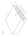
- FIG. 5 presents an external view of the information processing apparatus A 1.
- the information processing apparatus A 1 is housed in an 1DIN size case conforming to the DIN standard.
- Various dials 52 and 53, switches 54 and a display device 55 constituted with a 320 x 120 dot LCD, which are used for listening to radio broadcasts and the like, are mounted on a front panel 51.
- the current time point, the radio station to which the radio is currently tuned and other necessary information is displayed at the display device 55.
- the display device 55 is a smaller display device compared to the LCD panel 31, which can be manufactured at lower cost.
- the information processing system A adopting the structure described above executes control related to the audio equipment in the vehicle, control on the CAN, a route search, road guidance (navigation) along a recommended route determined through the search, and the like.
- the arithmetic processing unit 34 in the display device 3 is faster and achieves higher performance than the arithmetic processing unit 21 in the information processing apparatus A 1.
- the arithmetic processing unit 21 in the information processing apparatus A 1 executes control related to the audio equipment in the vehicle, processing on various types of sensor data provided by the GPS device 8, the gyro 9 and the like and processing for reading the road map data
- the arithmetic processing unit 34 in the display device 3 executes the arithmetic processing for map display and the arithmetic processing for route search by using the sensor data having been processed at the arithmetic processing unit 21 of the information processing apparatus A 1 and the road map data.
- the arithmetic processing unit 21 and the arithmetic processing unit 34 exchange commands and data in conformance to specific protocols.
- FIG. 6 is a block diagram of the internal structure adopted in the information processing apparatus B 2.
- the information processing apparatus B 2 comprises an arithmetic processing unit 21, an AM tuner 22, an FM multiplex tuner 23, an FM tuner 24, an audio amplifier 25, an optical fiber cable interface 26 and a CAN interface 27, all identical to those in the information processing apparatus A 1.
- the information processing apparatus B 2 does not include a GPS device 8 or a gyro 9. Namely, the information processing apparatus B 2 does not function as a car navigation system and only engages in audio control and CAN control.
- the information processing apparatus B 2 is capable of reading data on a music CD-ROM 4 by using the CD-ROM drive device 5 and thus, the user in the vehicle can listen to music stored in the CD-ROM 4.
- the information processing apparatus B 2 may include a television broadcast receiving device so as to allow the user to watch television broadcast via the display device 3.
- FIG. 7 shows how an information processing system B is achieved by connecting the information processing apparatus B 2 to the display device 3.
- the information processing apparatus B 2 and the display device 3 are connected with each other via a CAN cable 28 and the CAN interface 27. Alternatively, they may be connected by using an optical fiber cable and the optical fiber cable interface 26.
- the information processing apparatus B 2 is connected with speakers 41 installed in the vehicle through a cable 42.
- An FM antenna 43 is connected to the FM tuner 24 and the FM multiplex tuner 23 via a cable 44.
- the information processing apparatus B 2 is also connected with a control switch group 45 via a CAN cable 46 and the interface 27 (see FIG. 6 ). This means that the information processing apparatus B 2 also controls the CAN in the vehicle.
- the external appearance of the information processing apparatus B 2 is similar to that presented in FIG. 5 .
- the information processing system B implements control on the audio equipment in the vehicle and CAN control. However, it does not have a road guidance (navigation) function.
- the information processing system A or the information processing system B can be constituted through a combination of the information processing apparatus A 1 or the information processing apparatus B 2 and the display device 3 achieved in the embodiment.
- the user may initially install the less expensive information processing system B by combining the information processing apparatus B 2 and the display device 3. Then, the user may subsequently decide that he needs a navigation function and in such a case, he can install the navigation function with ease simply by replacing the information processing apparatus B 2 with the information processing apparatus A 1.
- the information processing apparatus A 1 and the information processing apparatus B 2 are identical except that the information processing apparatus A 1 includes the GPS device 8 and the gyro 9, a changeover to the information processing apparatus A 1 may be achieved simply by adding the GPS device 8 and the gyro 9 to the information processing apparatus B 2. While a common low-cost arithmetic processing unit 21 is utilized, the navigation function can be realized without problem since the high load navigation processing requiring high processing performance is executed at the high-performance arithmetic processing unit 34 in the display device 3.
- various types of information processing apparatuses can be provided by using a less expensive, lower performance arithmetic processing unit compared to the arithmetic processing unit in the display device, and the relatively high-performance arithmetic processing unit in the display device can be used in conjunction with the various information processing apparatuses.
- the relatively high-performance arithmetic processing unit in the display device can be used in conjunction with the various information processing apparatuses.
- the information processing apparatus A 1 includes audio circuits such as the AM tuner 22, the FM tuner 24 and the audio amplifier 25. These circuits tend to be readily affected by noise. Since a high-performance arithmetic processing unit that is driven by a high frequency clock is likely to become a source of noise, it is also extremely advantageous to separate the audio related circuits from the high-performance arithmetic processing unit from the viewpoint of noise suppression as well.
- the car navigation function is realized in the information processing system A which is constituted by combining the information processing apparatus A 1 with the display device 3.
- road guidance is provided by displaying a road map at the display device 3.
- car navigation can be provided through the information processing apparatus A 1 by itself if road guidance is to be provided through a simple display of an arrow or the like alone.
- arrow navigation the type of navigation provided simply by displaying an arrow without displaying a road map. Since the structure of the information processing apparatus in this embodiment is similar to that of the information processing apparatus A 1 in the first embodiment, its explanation is omitted.
- FIG. 8 shows a road map provided to facilitate the explanation of arrow navigation.
- Roads are expressed by nodes, links and link strings in the embodiment.
- a node is equivalent to an intersecting point of roads or a branching point of a road and a link is equivalent to a road that connects nodes.
- a link string is a string of a plurality of continuous links. For instance, National Highway #1 is divided into a plurality of link strings and a single link string represents National Highway #1 from a given point to another point.
- intersecting points and branching points are simply referred to as nodes and roads connecting intersecting points are simply referred to as links.
- Road data are stored in a CD-ROM 4.
- the road data are constituted with node connection data and guidance data.
- the arithmetic processing unit 21 reads the road data stored in the CD-ROM 4 with the CD-ROM drive device 5 and uses the road data thus read in arrow navigation control. These road data do not include data used for road map display.
- the node connection data contain connection information (network information) indicating how the nodes described above connect with other nodes.
- connection information network information
- the node connection data which contain the information related to the connections between nodes, can be used for route search and arrow navigation guidance.
- the guidance data include intersecting point data and branching point data. For instance, data indicating the names of intersecting points and branching points are stored as the guidance data. By using the guidance data, the name of a specific intersecting point and the like can be brought up on display when guiding the vehicle through the arrow navigation.
- FIG. 8 shows a road map over a specific range, displayed by using nodes, links and link strings explained above.
- Reference numerals N1 to N8 each indicate a node
- reference numerals L1 to L7 each indicate a link.
- the links L1, L2, L6 and L7 are all contained in a single link string.
- a triangle mark 61 indicates the current vehicle position (subject vehicle position), and the bold line indicates the recommended route calculated through a route search. In other words, the vehicle 61 is on its way to the destination by traveling through the node N1 and making a right turn, a left turn or the like at each of the nodes N2, N3 and N4.
- FIG. 9 (a) An arrow 71 shown in FIG. 9 (a) is displayed at the display device 55 while the vehicle 61 travels through the links L1 and L2.
- the display device 55 constituted with a 320 x 120 dot LCD, arrows indicating accurate degrees of turns as well as a straight arrow can be displayed.
- the arrow 71 is a simple upward facing arrow. This upward facing arrow 71 indicates that the vehicle is to travel straight ahead along the advancing direction. In other words, when the vehicle is to travel straight ahead along the advancing direction, the arrow on display remains facing upward regardless of the advancing azimuth of the vehicle.
- the vehicle While the vehicle travels past the node N1, it still only needs to advance through the links L1 and L2 in the same link string, and thus, the arrow 71 is displayed in this situation. It is to be noted that the current position of the vehicle 61 is calculated by the arithmetic processing unit 21 based upon the position signal provided by the GPS device 8.
- the display at the display device 55 is switched to an arrow 72 in FIG. 9(b) .
- the arrow 72 indicates that the vehicle is to make a 90° right turn at the next intersecting point.
- the arrow 72 with a 90° bend is displayed in this situation since the line connecting the node N2 to the node N3 forms an angle of approximately 90° relative to the line connecting the current vehicle position and the node N2.
- a decision as to whether or not the vehicle 61 is approaching the node N2 is made based upon the positional coordinates of the current vehicle position and the positional coordinates of the node N2.
- the positional coordinates of each node are stored in the node connection data explained earlier. For instance, when the current vehicle position is 100m to the node N2, the vehicle 61 may be judged to be approaching the node N2 and the arrow 72 may be brought up on display. The value used in this judgment may be other than 100m.
- the display at the display device 55 is switched to an arrow 73 shown in FIG. 9(c) .
- Turn information indicating a turn to make at the next node N3 is brought up on display immediately since the distance between the nodes N2 and N3 is equal to or less than 100m.
- the arrow 73 bends to the right at an angle of 45° since the line connecting the node N3 to the node N4 forms an angle of approximately 45° to the right relative to the line connecting the current vehicle position to the node N3.
- the display at the display device 55 is switched back to the arrow 71 in FIG. 9(a) , since the vehicle is to advance straight ahead through the link L4 for the time being.
- the display at the display device 55 is switched to an arrow 74 in FIG. 9(d) .
- the arrow 74 indicates that the vehicle is to make a 90° left turn at the next intersecting point.
- the arrow 74 with a 90° bend to the left is displayed since the line connecting the node N4 to the node N5 forms an angle of approximately 90° relative to the line connecting the current vehicle position and the node N4.
- FIG. 10 is a front view of a front panel 81 of the information processing apparatus A 1.
- various dials 82 and 83, switches 84 and a display device 85 constituted with a 320 x 120 dot LCD are mounted.
- an arrow display 86 for the arrow navigation, a current time point display 87 and a radio station display 88 indicating the radio station to which the radio is currently tuned are displayed.
- a slot 89 at which the CD-ROM is loaded is provided at the information processing apparatus. While the information processing apparatus A 1 only includes a CD-ROM drive device and only a CD-ROM, the display device may also have a DVD slot if the information processing apparatus includes a DVD drive device as well.
- the angle with which the arrow bends is calculated in reference to the next guidance point.
- the angle with which the arrow bends may be calculated in reference to the current vehicle position.
- the direction along which the vehicle 61 is to advance may be indicated based upon the angle formed by the line connecting the current position of the vehicle 61 and the positional coordinates of the second guidance point from the current position and the advancing direction of the vehicle 61.
- the degree of bend in the arrow changes subtly as the vehicle 61 approaches the next guidance point node.
- the angle with which the arrow bends matches the angle formed by the vehicle advancing direction and the direction along which the vehicle heads for the next guidance point node from the node it has just reached.
- the direction of the arrow indicates the direction toward the second guidance point from the current vehicle position at all times in this example.
- an arrow navigation function can be initially installed through an inexpensive information processing apparatus A 1 alone. Subsequently, if the user decides that he needs a navigation function with high-performance map display, he only needs to add the display device 3 and replace the control program in the information processing apparatus A 1.
Landscapes
- Engineering & Computer Science (AREA)
- Radar, Positioning & Navigation (AREA)
- Remote Sensing (AREA)
- Automation & Control Theory (AREA)
- Physics & Mathematics (AREA)
- General Physics & Mathematics (AREA)
- Navigation (AREA)
- Controls And Circuits For Display Device (AREA)
- Traffic Control Systems (AREA)
- Instructional Devices (AREA)
Claims (6)
- Anzeigevorrichtung (3) mit:einer ersten Rechenverarbeitungseinheit (34);einer Anzeigeeinheit (31, 32), die dazu ausgelegt ist, Information anzuzeigen; undeiner Schnittstelleneinheit (37, 38), die mit einem externen Informationsverarbeitungsgerät (1, 2) verbunden werden kann, das eine zweite Rechenverarbeitungseinheit (21) aufweist, die dazu ausgelegt ist, einen spezifischen Verarbeitungstyp auszuführen, und eine Antriebsvorrichtung (5, 7) aufweist, die dazu ausgelegt ist, Straßendaten von einer CD-ROM (4) oder einer DVD (6) zu lesen, wobei:die erste Rechenverarbeitungseinheit (34) dazu ausgelegt ist, die Anzeigeeinheit (31, 32) zu steuern, um Information anzuzeigen, die den spezifischen Verarbeitungstyp betrifft, der von dem externen Informationsverarbeitungsgerät (1, 2) übertragen wird, und auch dazu ausgelegt ist, einen weiteren Verarbeitungstyp, der den spezifischen Verarbeitungstyp betrifft, auf der Basis einer Anweisung auszuführen, die von dem externen informationsverarbeitungsgerät (1, 2) bereitgestellt wird, wenn das externe Informationsvorarbeitungsgerät (1, 2) mit der Schnittstelleneinheit (37, 38) verbunden ist;der an der zweiten Rechenverarbeitungseinheit (21) ausgeführte spezifische Verarbeitungstyp eine Verarbeitung, die eine Straßenführung betrifft, welche eine Aktuelle-Positions-Erfassungsverarbeitung mit GPS-Signalen enthält, und eine Verarbeitung zum Lesen der Straßendaten mit der Antriebsvorrichtung (5, 7) einschließt;der andere an der ersten Rechenverarbeitungseinheit (34) ausgeführte Verarbeitungstyp die Straßenkartendaten, die mit der Antriebsvorrichtung (5, 7) in dem externen Informationsverarbeitungsgerät (1, 2) gelesen werden, und die aktuelle Position, die von dem externen Informationsverarbeitungsgerät erfasstwird, verwendet und eine Rechenverarbeitung zum Anzeigen einer Straßenkarte auf der Anzeigeeinheit (31, 32) und eine Rechenverarbeitung für eine Routensuche einschließt; unddie erste Rechenverarbeitungseinheit (34) eine höhere Verarbeitungsleistung als die zweite Rechenverarbeitungseinheit (21) erzielt.
- Externes Informationsverarbeitungsgerät (1, 2) mit:einer Schnittstelleneinheit (26, 27), die mit einer Anzeigevorrichtung (3) verbunden werden kann, welche eine erste Rechenverarbeitungseinheit (34) und eine von der ersten Rechenverarbeitungseinheit (34) gesteuerte Anzeigeeinheit (31, 32) aufweist, die zur Anzeige von Information ausgelegt ist; undeiner zweiten Rechenverarbeitungseinheit (21), die dazu ausgelegt ist, einen spezifischen Verarbeitungstyp auszuführen;einer Antriebsvorrichtung (5, 7), die dazu ausgelegt ist, Straßendaten von einer CD-ROM (4) oder einer DVD (6) zu lesen, wobei:die zweite Rechenverarbeitungseinheit (21) dazu ausgelegt ist, eine Anweisung auszugeben, um die erste Rechenverarbeitungseinheit (34) an der Anzeigeeinheit (3) zu veranlassen, einen weiteren Verarbeitungstyp auszuführen, der den spezifischen Verarbeitungstyp betrifft, wenn die Schnittstelleneinheit mit der Anzeigevorrichtung (3) verbunden ist;der an der zweiten Rechenverarbeitungseinheit (21) ausgeführte spezifische Verarbeitungstyp eine Verarbeitung, die eine Straßenführung betrifft, welche eine Aktuelle-Positions-Erfassungsverarbeitung mit GPS-Signalen enthält, und eine Verarbeitung zum Lesen der Straßendaten mit der Antriebsvorrichtung (5, 7) einschließt;der andere an der ersten Rechenverarbeitungseinhelt (34) ausgeführte Verarbeitungstyp die Straßenkartendaten, die mit der Antriebsvorrichtung (5, 7) gelesen werden, und die aktuelle Position, die von der zweiten Rechenverarbeitungseinheit erfasst wird, verwendet und eine Rechenverarbeitung zum Anzeigen einer Straßenkarte auf der Anzeigeeinheit (31, 32) und eine Rechenverarbeitungfür eine Routensuche einschließt; unddie erste Rechenverarbeitungseinheit (34) eine höhere Verarbeitungsleistung als die zweite Rechenverarbeitungseinheit (21) erzielt.
- Informationsverarbeitungssystem mit:einer Anzeigevorrichtung (3) nach Anspruch 1; und einem externen Informationsverarbeitungsgerät (1, 2) nach Anspruch 2.
- Externes Informationsverarbeitungsgerät (1, 2) nach Anspruch 2, ferner mit:einer zweiten Anzeigeeinheit (55), die von kleinerer Größe als die Anzeigeeinheit (31, 32) der Anzeigevorrichtung (3) ist.
- Externes Informationsverarbeitungsgerät (1, 2) nach Anspruch 2, ferner mit:einer zweiten Anzeigeeinheit (55), die von kleinerer Größe als die Anzeigeeinheit (31, 32) der Anzeigevorrichtung (3) ist, wobei:die zweite Rechenverarbeitungseinheit (21) dazu ausgelegt ist, die Verarbeitung, welche die Straßenführung betrifft, durch Anzeigen eines geraden Pfeils oder eines gebogenen Pfeils auf der zweiten Anzeigeeinheit (55) ohne Anzeigen einer Karte auszuführen.
- Anzeigevorrichtung nach Anspruch 1, wobei:die Schnittstelleneinheit (37, 38) anstelle des externen Informationsverarbeitungsgeräts (1) mit einem weiteren externen Informationsverarbeitungsgerät (2) verbunden werden kann, das dazu ausgelegt ist, den spezifischen Verarbeitungstyp nicht auszuführen; unddie erste Rechenverarbeitungseinheit (34) dazu ausgelegt ist, den anderen Verarbeitungstyp, der den spezifischen Verarbeitungstyp betrifft, nicht auszuführen, wenn die Schnlitstelleneinheit (37, 38) mit dem anderen externen Informationsverarbeitungsgerät (2) verbunden ist.
Applications Claiming Priority (3)
| Application Number | Priority Date | Filing Date | Title |
|---|---|---|---|
| JP2002117504 | 2002-04-19 | ||
| JP2002117504A JP3895633B2 (ja) | 2002-04-19 | 2002-04-19 | 表示装置、情報処理装置、情報処理システム |
| PCT/JP2003/004977 WO2003089879A1 (en) | 2002-04-19 | 2003-04-18 | Display device, information processing device, and information processing system |
Publications (3)
| Publication Number | Publication Date |
|---|---|
| EP1500906A1 EP1500906A1 (de) | 2005-01-26 |
| EP1500906A4 EP1500906A4 (de) | 2010-04-21 |
| EP1500906B1 true EP1500906B1 (de) | 2014-01-29 |
Family
ID=29243497
Family Applications (1)
| Application Number | Title | Priority Date | Filing Date |
|---|---|---|---|
| EP03725606.2A Expired - Lifetime EP1500906B1 (de) | 2002-04-19 | 2003-04-18 | Anzeigeeinrichtung, informationsverarbeitungseinrichtung und informationsverarbeitungssystem |
Country Status (4)
| Country | Link |
|---|---|
| US (1) | US7231296B2 (de) |
| EP (1) | EP1500906B1 (de) |
| JP (1) | JP3895633B2 (de) |
| WO (1) | WO2003089879A1 (de) |
Families Citing this family (1)
| Publication number | Priority date | Publication date | Assignee | Title |
|---|---|---|---|---|
| KR20230155616A (ko) | 2016-09-23 | 2023-11-10 | 이노비오 파마수티컬즈, 인크. | 전기천공을 사용하여 지방 조직의 생체내 형질감염을 최소로 침습성으로 하기 위한 방법 및 장치 |
Family Cites Families (18)
| Publication number | Priority date | Publication date | Assignee | Title |
|---|---|---|---|---|
| JPH05265374A (ja) | 1992-03-16 | 1993-10-15 | Clarion Co Ltd | 車載用ナビゲーション装置 |
| JP3198883B2 (ja) | 1995-08-24 | 2001-08-13 | トヨタ自動車株式会社 | 移動スケジュール処理装置 |
| US5794164A (en) * | 1995-11-29 | 1998-08-11 | Microsoft Corporation | Vehicle computer system |
| JP3796884B2 (ja) * | 1997-03-31 | 2006-07-12 | マツダ株式会社 | 自動車用制御装置の操作装置 |
| DE69841092D1 (de) | 1998-01-07 | 2009-10-08 | Clarion Co Ltd | Anzeigesteuergerät und -verfahren für eine Navigationseinheit |
| DE19927647A1 (de) | 1999-06-17 | 2000-12-21 | Grundig Ag | Fahrzeugnavigationssystem |
| DE69936922T2 (de) * | 1999-06-22 | 2008-05-15 | Mitsubishi Denki K.K. | Mobilendgerät und server in einem navigationssystem |
| JP3896728B2 (ja) * | 1999-06-23 | 2007-03-22 | トヨタ自動車株式会社 | 携帯型端末装置及び車載情報処理装置 |
| US6654683B2 (en) | 1999-09-27 | 2003-11-25 | Jin Haiping | Method and system for real-time navigation using mobile telephones |
| JP2001159525A (ja) * | 1999-11-30 | 2001-06-12 | Mitsubishi Electric Corp | ナビゲーション装置および記録媒体 |
| EP1130358B1 (de) | 2000-03-01 | 2006-06-28 | Matsushita Electric Industrial Co., Ltd. | Navigationsvorrichtung |
| DE10014500C1 (de) * | 2000-03-23 | 2001-10-04 | Kid Systeme Gmbh | Schutzsteckdose mit Sicherheitsvorrichtung |
| KR100353649B1 (ko) * | 2000-08-18 | 2002-09-28 | 삼성전자 주식회사 | 무선망을 이용한 네비게이션 시스템 및 그에 의한 경로안내 방법 |
| JP3616003B2 (ja) | 2000-09-29 | 2005-02-02 | 東京エレクトロン株式会社 | 塗布膜形成方法及びその装置 |
| EP1258706A2 (de) | 2001-05-15 | 2002-11-20 | Matsushita Electric Industrial Co., Ltd. | Navigationssystem |
| JP4163397B2 (ja) * | 2001-06-08 | 2008-10-08 | アルパイン株式会社 | 経路誘導装置 |
| JP2003121183A (ja) * | 2001-10-17 | 2003-04-23 | Pioneer Electronic Corp | ナビゲーション装置及びナビゲーション方法、ナビゲーション用プログラム、情報記録媒体 |
| JP3594011B2 (ja) * | 2001-11-30 | 2004-11-24 | 株式会社デンソー | ナビゲーション装置 |
-
2002
- 2002-04-19 JP JP2002117504A patent/JP3895633B2/ja not_active Expired - Fee Related
-
2003
- 2003-04-18 US US10/511,760 patent/US7231296B2/en not_active Expired - Lifetime
- 2003-04-18 EP EP03725606.2A patent/EP1500906B1/de not_active Expired - Lifetime
- 2003-04-18 WO PCT/JP2003/004977 patent/WO2003089879A1/ja not_active Ceased
Also Published As
| Publication number | Publication date |
|---|---|
| EP1500906A1 (de) | 2005-01-26 |
| JP3895633B2 (ja) | 2007-03-22 |
| WO2003089879A1 (en) | 2003-10-30 |
| JP2003317190A (ja) | 2003-11-07 |
| US20050182562A1 (en) | 2005-08-18 |
| EP1500906A4 (de) | 2010-04-21 |
| US7231296B2 (en) | 2007-06-12 |
Similar Documents
| Publication | Publication Date | Title |
|---|---|---|
| US6952643B2 (en) | Road traffic information output apparatus | |
| US7355525B2 (en) | Vehicle communication system | |
| KR20020021691A (ko) | 단거리 고속통신 장치를 이용한 차량항법 서비스 장치 및그 방법 | |
| CN101578501A (zh) | 导航装置及方法 | |
| US8548737B2 (en) | Navigation apparatus | |
| JP2008116431A (ja) | 車両動態ナビゲーション方法及びシステム | |
| US20090198440A1 (en) | Inter-vehicle communication apparatus and inter-vehicle communication method | |
| JP2006162596A (ja) | ナビゲーションシステム及び携帯端末機 | |
| EP1500906B1 (de) | Anzeigeeinrichtung, informationsverarbeitungseinrichtung und informationsverarbeitungssystem | |
| JPH11337348A (ja) | 車載用複合ユニット | |
| US8427339B2 (en) | Information provision system and in-vehicle apparatus | |
| JP3798731B2 (ja) | ナビゲーション装置、データ配信システム及びデータ配信方法 | |
| JP2000310543A (ja) | カーナビゲーションシステム | |
| JP2009133732A (ja) | 車両用ナビゲーション装置 | |
| JP3682197B2 (ja) | ナビゲーション信号受信装置及びナビゲーション信号受信方法 | |
| JP4137397B2 (ja) | 車両用ナビゲーション装置 | |
| JPH1062183A (ja) | 車載ナビゲーションシステム | |
| JP2006292672A (ja) | 道路交通情報システムの車両用受信装置 | |
| JP3173422B2 (ja) | ビーコン位置提供装置 | |
| KR20090121067A (ko) | 차량용 네비게이션 시스템의 경로 설정 방법 | |
| JP2002048556A (ja) | 施設情報報知装置及びナビゲーション装置 | |
| JPH06195593A (ja) | 緊急車両走行情報伝達装置 | |
| JPH0887698A (ja) | 車載用ナビゲーション装置 | |
| JP5619530B2 (ja) | 移動体通信装置 | |
| JPH09138134A (ja) | 車両用経路誘導装置 |
Legal Events
| Date | Code | Title | Description |
|---|---|---|---|
| PUAI | Public reference made under article 153(3) epc to a published international application that has entered the european phase |
Free format text: ORIGINAL CODE: 0009012 |
|
| 17P | Request for examination filed |
Effective date: 20041116 |
|
| AK | Designated contracting states |
Kind code of ref document: A1 Designated state(s): AT BE BG CH CY CZ DE DK EE ES FI FR GB GR HU IE IT LI LU MC NL PT RO SE SI SK TR |
|
| A4 | Supplementary search report drawn up and despatched |
Effective date: 20100319 |
|
| 17Q | First examination report despatched |
Effective date: 20100729 |
|
| REG | Reference to a national code |
Ref country code: DE Ref legal event code: R079 Ref document number: 60345672 Country of ref document: DE Free format text: PREVIOUS MAIN CLASS: G01C0021260000 Ipc: G01C0021360000 |
|
| GRAP | Despatch of communication of intention to grant a patent |
Free format text: ORIGINAL CODE: EPIDOSNIGR1 |
|
| RIC1 | Information provided on ipc code assigned before grant |
Ipc: G01C 21/36 20060101AFI20130715BHEP |
|
| INTG | Intention to grant announced |
Effective date: 20130819 |
|
| GRAS | Grant fee paid |
Free format text: ORIGINAL CODE: EPIDOSNIGR3 |
|
| GRAA | (expected) grant |
Free format text: ORIGINAL CODE: 0009210 |
|
| AK | Designated contracting states |
Kind code of ref document: B1 Designated state(s): DE |
|
| REG | Reference to a national code |
Ref country code: DE Ref legal event code: R096 Ref document number: 60345672 Country of ref document: DE Effective date: 20140313 |
|
| REG | Reference to a national code |
Ref country code: DE Ref legal event code: R097 Ref document number: 60345672 Country of ref document: DE |
|
| PLBE | No opposition filed within time limit |
Free format text: ORIGINAL CODE: 0009261 |
|
| STAA | Information on the status of an ep patent application or granted ep patent |
Free format text: STATUS: NO OPPOSITION FILED WITHIN TIME LIMIT |
|
| 26N | No opposition filed |
Effective date: 20141030 |
|
| REG | Reference to a national code |
Ref country code: DE Ref legal event code: R097 Ref document number: 60345672 Country of ref document: DE Effective date: 20141030 |
|
| PGFP | Annual fee paid to national office [announced via postgrant information from national office to epo] |
Ref country code: DE Payment date: 20210323 Year of fee payment: 19 |
|
| REG | Reference to a national code |
Ref country code: DE Ref legal event code: R119 Ref document number: 60345672 Country of ref document: DE |
|
| PG25 | Lapsed in a contracting state [announced via postgrant information from national office to epo] |
Ref country code: DE Free format text: LAPSE BECAUSE OF NON-PAYMENT OF DUE FEES Effective date: 20221103 |