EP1498546B1 - Räumkette zum Transport von Schotter einer Gleisbettung - Google Patents
Räumkette zum Transport von Schotter einer Gleisbettung Download PDFInfo
- Publication number
- EP1498546B1 EP1498546B1 EP04102874A EP04102874A EP1498546B1 EP 1498546 B1 EP1498546 B1 EP 1498546B1 EP 04102874 A EP04102874 A EP 04102874A EP 04102874 A EP04102874 A EP 04102874A EP 1498546 B1 EP1498546 B1 EP 1498546B1
- Authority
- EP
- European Patent Office
- Prior art keywords
- clearing chain
- circular arc
- guide
- plane
- glide track
- Prior art date
- Legal status (The legal status is an assumption and is not a legal conclusion. Google has not performed a legal analysis and makes no representation as to the accuracy of the status listed.)
- Expired - Lifetime
Links
Images

Classifications
-
- E—FIXED CONSTRUCTIONS
- E01—CONSTRUCTION OF ROADS, RAILWAYS, OR BRIDGES
- E01B—PERMANENT WAY; PERMANENT-WAY TOOLS; MACHINES FOR MAKING RAILWAYS OF ALL KINDS
- E01B27/00—Placing, renewing, working, cleaning, or taking-up the ballast, with or without concurrent work on the track; Devices therefor; Packing sleepers
- E01B27/04—Removing the ballast; Machines therefor, whether or not additionally adapted for taking-up ballast
-
- E—FIXED CONSTRUCTIONS
- E02—HYDRAULIC ENGINEERING; FOUNDATIONS; SOIL SHIFTING
- E02F—DREDGING; SOIL-SHIFTING
- E02F3/00—Dredgers; Soil-shifting machines
- E02F3/04—Dredgers; Soil-shifting machines mechanically-driven
- E02F3/08—Dredgers; Soil-shifting machines mechanically-driven with digging elements on an endless chain
- E02F3/12—Component parts, e.g. bucket troughs
- E02F3/14—Buckets; Chains; Guides for buckets or chains; Drives for chains
- E02F3/142—Buckets; Chains; Guides for buckets or chains; Drives for chains tools mounted on buckets or chains which loosen the soil, e.g. cutting wheels, or the like
-
- E—FIXED CONSTRUCTIONS
- E02—HYDRAULIC ENGINEERING; FOUNDATIONS; SOIL SHIFTING
- E02F—DREDGING; SOIL-SHIFTING
- E02F3/00—Dredgers; Soil-shifting machines
- E02F3/04—Dredgers; Soil-shifting machines mechanically-driven
- E02F3/08—Dredgers; Soil-shifting machines mechanically-driven with digging elements on an endless chain
- E02F3/12—Component parts, e.g. bucket troughs
- E02F3/14—Buckets; Chains; Guides for buckets or chains; Drives for chains
- E02F3/143—Buckets; Chains; Guides for buckets or chains; Drives for chains chains; chain links; scraper chains
Definitions
- the invention relates to a clearing chain for the transport of ballast of a track bed according to the features cited in the preamble of claim 1.
- the object of the present invention is now to provide a clearing chain of the generic type, with an improved functionality of the clearing chain is made possible without affecting the articulated connection.
- This feature combination makes it possible to redirect the clearing chain even at high loads without affecting the joint only by sliding friction. Due to the special curvature of the Stirngleitbahn a trouble-free transfer of the clearing chain is ensured on the longitudinal guide even in the case of a larger bend of longitudinal and transverse guidance. Thus, the use of a previously considered by the professional world in connection with a joint deflection roller is unnecessary. This is due to the extreme stress highest quality and thus very expensive form and also equipped with a complex lubricant supply.
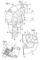
- a clearing chain 1 shown in FIG. 1 is arranged on a machine 2 for cleaning a track bed 3.
- the broaching 1 is during work under a raised track 4 as an endless chain order arranged around this.
- contaminated ballast 5 is conveyed to a screening plant 6.
- the gravel 5 cleaned therein is then reintroduced into the track 4 in a manner already known.
- the rotation of the clearing chain 1 takes place in a plane of rotation 7, which is arranged inclined to a Bettungsebene 8.
- a transverse guide 9 is positioned in a section line of the two planes 7, 8, which extends transversely across the track bed 3.
- the transverse guide 9 is articulated by guide joints 10 at a respective curved end 11 to a longitudinal guide 12.
- the two longitudinal guides 12 form with the transverse guide 9 a guide channel 13 (FIG. 5) for the storage and guidance of the clearing chain 1.
- the transverse guide 9 can be extended for a ballast receiving in a switch section.
- the broaching chain 1 is composed of a multiplicity of chain links 15 interconnected by chain pins 14.
- the clearing chain 1 of the guide channel 13 which is composed of a lower and upper slide 17 and a connecting them together Stirngleitbahn 18. This runs normal to the plane of rotation 7.
- the slides 17,18 are made of highly wear-resistant material and releasably connected to the guide channel 13.
- the Stirngleitbahn 18 of the transverse guide 9 is curved in the form of a circular arc 19 in the direction of the hinge 10, so that an extension of the Stirngleitbahn 18 of the longitudinal guide 12 an acute angle ⁇ of preferably about 45 ° included becomes.
- the circular arc 19 has a positioned in a hinge axis 21 of the guide joint 10 circle center.
- a by the adjacent longitudinal guide 12 on the one hand and the hinge axis 21 on the other limited, normal to Stirngleitbahn 18 of the longitudinal guide 12 extending distance a is identical to a circular arc radius r of the curved transverse end 20.
- the circular arc 19 forms a circular segment with an angle ⁇ of 60 °.
- the Stirngleitbahn 18 has between a rectilinear portion 23 of the transverse guide 9 and the circular arc-shaped transverse end 20, a second circular arc portion 24, the center of the circle is positioned on a rectilinear portion 23 parallel, passing through the hinge axis 21 straight line 26.
- the clearing chain 1 can be deflected without the aid of a guide roller only by sliding friction.
Landscapes
- Engineering & Computer Science (AREA)
- Mechanical Engineering (AREA)
- Civil Engineering (AREA)
- Structural Engineering (AREA)
- Mining & Mineral Resources (AREA)
- General Engineering & Computer Science (AREA)
- Architecture (AREA)
- Machines For Laying And Maintaining Railways (AREA)
- Chain Conveyers (AREA)
- Framework For Endless Conveyors (AREA)
- Devices For Conveying Motion By Means Of Endless Flexible Members (AREA)
Description
- Die Erfindung betrifft eine Räumkette zum Transport von Schotter einer Gleisbettung gemäß den im Oberbegriff von Anspruch 1 angeführten Merkmalen.
- Durch US 4 614 238, US 4 014 389, DE 3 151 652, sind bereits derartige endlos ausgebildete, um das Gleis herum rotierende Räumketten bekannt. Diese setzen sich im wesentlichen aus einer mit der Gleisbettung in Kontakt stehenden Querführung und zwei mit dieser gelenkig verbundenen Längsführungen zusammen. Koaxial zur Gelenkachse ist jeweils eine Umlenkrolle positioniert, durch die die Räumkette um wenigstens 90° umgelenkt wird. Die gelenkige Verbindung von Quer- und Längsführung ist insofern notwendig, als damit die Möglichkeit einer geringfügigen Verschiebung der Räumkette relativ zum Gleis besteht. Damit kann in räumlich z.B. durch einen Bahnsteig eingeschränkten Abschnitten besser gearbeitet werden. Außerdem ermöglicht die Gelenkverbindung eine Verlängerung der Querführung zum Reinigen eines Weichenabschnittes. Da bei leistungsfähigen Reinigungsmaschinen auf die Räumkette eine Zugkraft von etwa 100 Kilonewton einwirkt, sind die mit einer ausreichenden Schmierung zu versorgenden Umlenkrollen höchsten Belastungen ausgesetzt und häufig zu erneuern.
- Die Aufgabe der vorliegenden Erfindung liegt nun in der Schaffung einer Räumkette der gattungsgemäßen Art, mit der ohne Beeinträchtigung der gelenkigen Verbindung eine verbesserte Funktionsfähigkeit der Räumkette ermöglicht wird.
- Erfindungsgemäß wird diese Aufgabe mit einer Räumkette der eingangs genannten Art durch die im Kennzeichen von Anspruch 1 angeführten Merkmale gelöst.
- Durch diese Merkmalskombination ist es möglich, die Räumkette auch bei hohen Belastungen ohne Beeinträchtigung der Gelenkverbindung lediglich durch Gleitreibung umzulenken. Durch die spezielle Krümmung der Stirngleitbahn ist auch im Falle einer größeren Abwinkelung von Längs- und Querführung eine problemlose Überführung der Räumkette auf die Längsführung gewährleistet. Damit erübrigt sich der Einsatz einer bisher von der Fachwelt in Verbindung mit einem Gelenk als unumgänglich betrachteten Umlenkrolle. Diese ist durch die extreme Belastung hochwertigst und damit sehr teuer auszubilden und außerdem mit einer aufwendigen Schmiermittelversorgung auszustatten.
- Weitere Vorteile und Ausbildungen der Erfindung ergeben sich aus den weiteren Ansprüchen und der Zeichnung.
- Im folgenden wird die Erfindung anhand von in der Zeichnung dargestellten Ausführungsbeispielen näher beschrieben.
- Es zeigen:
- Fig. 1
- eine Seitenansicht einer Reinigungsmaschine mit einer Räumkette,
- Fig. 2
- eine vereinfachte Draufsicht auf die Räumkette,
- Fig. 3, 4
- je eine vergrößerte Draufsicht auf eine Umlenkung der Räumkette,
- Fig. 5
- einen Querschnitt durch einen Führungskanal, und
- Fig. 6
- eine bekannte Umlenkung mit einer Umlenkrolle.
- Eine in Fig. 1 ersichtliche Räumkette 1 ist an einer Maschine 2 zur Reinigung einer Gleisbettung 3 angeordnet. Die Räumkette 1 ist während des Arbeitseinsatzes unterhalb eines angehobenen Gleises 4 als Endloskette um dieses herumgeführt angeordnet. Dabei wird verunreinigter Schotter 5 zu einer Siebanlage 6 gefördert. Der darin gereinigte Schotter 5 wird dann auf bereits bekannte Art und Weise wieder in das Gleis 4 eingebracht. Die Rotation der Räumkette 1 erfolgt in einer Rotationsebene 7, die zu einer Bettungsebene 8 geneigt angeordnet ist. Im Arbeitseinsatz der Räumkette 1 ist in einer Schnittlinie der beiden Ebenen 7,8 eine Querführung 9 positioniert, die sich quer über die Gleisbettung 3 erstreckt.
- Wie in Fig. 2 ersichtlich, ist die Querführung 9 durch Führungsgelenke 10 jeweils an einem gekrümmten Ende 11 mit einer Längsführung 12 gelenkig verbunden. Die beiden Längsführungen 12 bilden mit der Querführung 9 einen Führungskanal 13 (Fig. 5) zur Lagerung und Führung der Räumkette 1. Wie in strichpunktierten Linien angedeutet, kann die Querführung 9 für eine Schotteraufnahme in einem Weichenabschnitt verlängert werden.
- Wie insbesondere in Fig. 3 und 5 ersichtlich, setzt sich die Räumkette 1 aus einer Vielzahl von durch Kettenbolzen 14 miteinander verbundenen Kettengliedern 15 zusammen. Zur Führung der Räumkette 1 dient der Führungskanal 13, der sich aus einer unteren und oberen Gleitbahn 17 sowie einer diese miteinander verbindenden Stirngleitbahn 18 zusammensetzt. Diese verläuft normal zur Rotationsebene 7. Die Gleitbahnen 17,18 sind aus hochverschleißfestem Material und lösbar mit dem Führungskanal 13 verbunden.
- Wie insbesondere in Fig. 3 und 4 ersichtlich, ist die Stirngleitbahn 18 der Querführung 9 in Form eines Kreisbogens 19 in Richtung zum Führungsgelenk 10 gekrümmt, so dass mit einer Verlängerung der Stirngleitbahn 18 der Längsführung 12 ein spitzer Winkel α von vorzugsweise etwa 45° eingeschlossen wird. Damit entsteht ein gekrümmtes Querführungsende 20 der Stirngleitbahn 18, das erst dann mit der Räumkette 1 in Kontakt kommt, wenn zwischen Längs- und Querführung 12, 9 eine Winkelveränderung stattfindet, beispielsweise im Falle einer in Fig. 2 angedeuteten Verlängerung der Querführung 9. Der Kreisbogen 19 weist einen in einer Gelenkachse 21 des Führungsgelenkes 10 positionierten Kreismittelpunkt auf.
- Ein durch die angrenzende Längsführung 12 einerseits und die Gelenkachse 21 andererseits begrenzter, normal zur Stirngleitbahn 18 der Längsführung 12 verlaufender Abstand a ist identisch mit einem Kreisbogenradius r des gekrümmten Querführungsendes 20. Der Kreisbogen 19 bildet ein Kreissegment mit einem Winkel β von 60°. Die Stirngleitbahn 18 weist zwischen einem geradlinigen Abschnitt 23 der Querführung 9 und dem kreisbogenförmigen Querführungsende 20 einen zweiten Kreisbogenabschnitt 24 auf, dessen Kreismittelpunkt auf einer zum geradlinigen Abschnitt 23 parallel verlaufenden, durch die Gelenkachse 21 führenden Geraden 26 positioniert ist.
- Durch diese spezielle Ausbildung des Endes 20 der Querführung 9 kann die Räumkette 1 ohne Zuhilfenahme einer Umlenkrolle lediglich durch Gleitreibung umgelenkt werden. Die Räumkette 1 wird z. B. bei einer leistungsfähigen Reinigungsmaschine mit einer Zugkraft von 110 Kilonewton in der durch einen Pfeil in Fig. 3 dargestellten Förderrichtung gezogen.
- Gemäß einer in Fig. 6 dargestellten bekannten Lösung erfolgt die Umlenkung der Räumkette 1 um eine Umlenkrolle 27, die in der Gelenkachse 21 drehbar gelagert ist und durch eine Öffnung der Stirngleitbahn 18 über deren Gleitebene vorragt. Damit ist die mit einer Schmierung zu versorgende Umlenkrolle 27 - insbesondere bei einer stärkeren Abwinkelung zwischen Längs- und Querführung 12, 9 - sehr hohen Belastungen ausgesetzt. Außerdem werden die Kettenbolzen 14 extremen Beanspruchungen unterworfen.
Claims (5)
- Räumkette (1) zum Transport von Schotter (5) einer Gleisbettung (3), bestehend aus einer Vielzahl von gelenkig miteinander verbundenen Kettengliedern (15), wobei die zur Rotation in einer zu einer Bettungsebene (8) geneigt angeordneten Rotationsebene (7) vorgesehene Räumkette (1) eine - im Arbeitseinsatz in einer Schnittlinie von Bettungs- und Rotationsebene (8,7) positionierte und zur Lagerung der Räumkette (1) vorgesehene - Querführung (9) aufweist, die durch Führungsgelenke (10) mit Längsführungen (12) verbunden ist, wobei ein durch Längs- und Querführungen (12,9) gebildeter Führungskanal (13) eine untere und obere, parallel zur Rotationsebene (7) verlaufende Gleitbahn (17) sowie eine diese miteinander verbindende, normal zur Rotationsebene (7) verlaufende Stirngleitbahn (18) aufweist, dadurch gekennzeichnet, dass die Stirngleitbahn (18) der Querführung (9) in deren an die Längsführung (12) angrenzenden Ende (11) in Richtung zum Führungsgelenk (10) gekrümmt ausgebildet ist, so dass mit einer Verlängerung der Stirngleitbahn (18) der Längsführung (12) ein spitzer Winkel α eingeschlossen wird, wobei für die Umlenkung der Räumkette (1) ausschließlich eine Kontaktierung zwischen Räumkette (1) und der Stirngleitbahn (18) vorgesehen ist.
- Räumkette nach Anspruch 1, dadurch gekennzeichnet, dass die Stirngleitbahn (18) des Endes (11) der Querführung (9) in Form eines Kreisbogens (19) mit einem in einer Gelenkachse (21) des angrenzenden Führungsgelenkes (10) positionierten Kreismittelpunkt gekrümmt ist.
- Räumkette nach Anspruch 2, dadurch gekennzeichnet, dass ein durch die angrenzende Längsführung (12) einerseits und die Gelenkachse (21) andererseits begrenzter, normal zur Stirngleitbahn (18) der Längsführung (12) verlaufender Abstand (a) identisch mit einem Kreisbogenradius (r) des Kreisbogens (19) ist.
- Räumkette nach Anspruch 2 oder 3, dadurch gekennzeichnet, dass der Kreisbogen (19) des Endes (11) der Querführung (9) mit der Gelenkachse (21) ein Kreissegment mit einem Winkel β von 60° bildet.
- Räumkette nach einem der Ansprüche 1 bis 4, dadurch gekennzeichnet, dass die Stirngleitbahn (18) zwischen einem geradlinigen Abschnitt (23) der Querführung (9) und dem kreisbogenförmigen Ende (11) einen zweiten Kreisbogenabschnitt (24) aufweist, dessen Kreismittelpunkt auf einer zum geradlinigen Abschnitt (23) parallel verlaufenden, durch die Gelenkachse (21) führenden Geraden (26) positioniert ist.
Priority Applications (2)
| Application Number | Priority Date | Filing Date | Title |
|---|---|---|---|
| PL04102874T PL1498546T3 (pl) | 2003-07-15 | 2004-06-22 | Zgarniacz łańcuchowy do transportu tłucznia warstwy podsypki |
| AT04102874T ATE343018T1 (de) | 2003-07-15 | 2004-06-22 | Räumkette zum transport von schotter einer gleisbettung |
Applications Claiming Priority (2)
| Application Number | Priority Date | Filing Date | Title |
|---|---|---|---|
| AT5002003U | 2003-07-15 | ||
| AT0050003U AT6487U3 (de) | 2003-07-15 | 2003-07-15 | Räumkette zum transport von schotter einer gleisbettung |
Publications (2)
| Publication Number | Publication Date |
|---|---|
| EP1498546A1 EP1498546A1 (de) | 2005-01-19 |
| EP1498546B1 true EP1498546B1 (de) | 2006-10-18 |
Family
ID=28679307
Family Applications (1)
| Application Number | Title | Priority Date | Filing Date |
|---|---|---|---|
| EP04102874A Expired - Lifetime EP1498546B1 (de) | 2003-07-15 | 2004-06-22 | Räumkette zum Transport von Schotter einer Gleisbettung |
Country Status (11)
| Country | Link |
|---|---|
| US (1) | US6981556B2 (de) |
| EP (1) | EP1498546B1 (de) |
| JP (1) | JP4614426B2 (de) |
| CN (1) | CN1280486C (de) |
| AT (2) | AT6487U3 (de) |
| AU (1) | AU2004202978B2 (de) |
| DE (1) | DE502004001771D1 (de) |
| DK (1) | DK1498546T3 (de) |
| ES (1) | ES2276224T3 (de) |
| PL (1) | PL1498546T3 (de) |
| UA (1) | UA83621C2 (de) |
Families Citing this family (11)
| Publication number | Priority date | Publication date | Assignee | Title |
|---|---|---|---|---|
| US8352400B2 (en) | 1991-12-23 | 2013-01-08 | Hoffberg Steven M | Adaptive pattern recognition based controller apparatus and method and human-factored interface therefore |
| US7904187B2 (en) | 1999-02-01 | 2011-03-08 | Hoffberg Steven M | Internet appliance system and method |
| KR100646448B1 (ko) | 2004-11-23 | 2006-11-15 | 한국철도공사 | 밸러스트 클리너용 커터 바 |
| US20070162516A1 (en) * | 2005-12-30 | 2007-07-12 | Microsoft Corporation | Computing asynchronous transaction log replication progress based on file change notifications |
| AT507672B1 (de) * | 2009-04-07 | 2010-07-15 | Plasser Bahnbaumasch Franz | Speicherwagen zum transport von schüttgut und verfahren |
| CH705701B1 (de) | 2011-10-18 | 2015-06-30 | Matisa Matériel Ind Sa | Maschine zur Aufnahme von Schotter eines Gleises, mit einer Aushubvorrichtung. |
| AT512163B1 (de) * | 2012-06-12 | 2013-06-15 | Plasser Bahnbaumasch Franz | Maschine mit einer Räumkette zum Transport von Schotter sowie Verfahren |
| CN104389248B (zh) * | 2013-12-25 | 2016-01-06 | 金鹰重型工程机械有限公司 | 一种用于挖掘轨道道砟的装置 |
| FR3101891B1 (fr) * | 2019-10-14 | 2021-10-08 | Matisa Materiel Ind Sa | maillon pour une chaîne d’excavation et chaine d’excavation associée |
| CN110725167A (zh) * | 2019-11-19 | 2020-01-24 | 常州市瑞泰工程机械有限公司 | 挖掘链单元、挖掘链和边坡清筛车 |
| AT523620B1 (de) | 2020-03-11 | 2025-03-15 | Plasser & Theurer Export Von Bahnbaumaschinen Gmbh | Gleisbaumaschine mit einer Förder- bzw. Räumkettenanordnung |
Family Cites Families (7)
| Publication number | Priority date | Publication date | Assignee | Title |
|---|---|---|---|---|
| AT343714B (de) * | 1974-08-14 | 1978-06-12 | Plasser Bahnbaumasch Franz | Forderkette fur gleisbaumaschinen mit kettenspannvorrichtung |
| AR205066A1 (es) * | 1975-01-10 | 1976-03-31 | Plasser Bahnbaumasch Franz | Maquina rodante para ferrovias mas en particular maquina limpiadora de agujas |
| AT370463B (de) * | 1981-04-22 | 1983-04-11 | Plasser Bahnbaumasch Franz | Umlenk- und fuehrungseinrichtung fuer endlosraeumund foerderketten von gleisbaumaschinen |
| AT375426B (de) * | 1982-09-20 | 1984-08-10 | Plasser Bahnbaumasch Franz | Foerder- bzw. raeumkettenanordnung fuer eine gleisbaumaschine |
| AT377551B (de) * | 1983-01-10 | 1985-04-10 | Plasser Bahnbaumasch Franz | Foerder- bzw. raeumkettenanordnung fuer gleisbaumaschinen |
| DE10019051A1 (de) * | 2000-04-18 | 2001-10-25 | Flexon Systemplast Gmbh | Kurvenführung für eine Förderkette |
| AT4763U3 (de) * | 2001-05-03 | 2002-03-25 | Plasser Bahnbaumasch Franz | Verfahren zur erneuerung einer schotterbettung sowie maschine |
-
2003
- 2003-07-15 AT AT0050003U patent/AT6487U3/de not_active IP Right Cessation
-
2004
- 2004-06-22 DK DK04102874T patent/DK1498546T3/da active
- 2004-06-22 DE DE502004001771T patent/DE502004001771D1/de not_active Expired - Lifetime
- 2004-06-22 PL PL04102874T patent/PL1498546T3/pl unknown
- 2004-06-22 EP EP04102874A patent/EP1498546B1/de not_active Expired - Lifetime
- 2004-06-22 ES ES04102874T patent/ES2276224T3/es not_active Expired - Lifetime
- 2004-06-22 AT AT04102874T patent/ATE343018T1/de active
- 2004-06-29 AU AU2004202978A patent/AU2004202978B2/en not_active Ceased
- 2004-07-12 JP JP2004204855A patent/JP4614426B2/ja not_active Expired - Fee Related
- 2004-07-13 UA UA20040705722A patent/UA83621C2/ru unknown
- 2004-07-13 US US10/890,030 patent/US6981556B2/en not_active Expired - Fee Related
- 2004-07-15 CN CNB2004100684178A patent/CN1280486C/zh not_active Expired - Fee Related
Also Published As
| Publication number | Publication date |
|---|---|
| AT6487U2 (de) | 2003-11-25 |
| ES2276224T3 (es) | 2007-06-16 |
| AU2004202978A1 (en) | 2005-02-03 |
| CN1576462A (zh) | 2005-02-09 |
| EP1498546A1 (de) | 2005-01-19 |
| DE502004001771D1 (de) | 2006-11-30 |
| US6981556B2 (en) | 2006-01-03 |
| CN1280486C (zh) | 2006-10-18 |
| PL1498546T3 (pl) | 2007-04-30 |
| AT6487U3 (de) | 2004-10-25 |
| JP2005036644A (ja) | 2005-02-10 |
| JP4614426B2 (ja) | 2011-01-19 |
| ATE343018T1 (de) | 2006-11-15 |
| AU2004202978B2 (en) | 2007-07-26 |
| DK1498546T3 (da) | 2007-02-19 |
| UA83621C2 (ru) | 2008-08-11 |
| US20050011088A1 (en) | 2005-01-20 |
Similar Documents
| Publication | Publication Date | Title |
|---|---|---|
| DE19839575A1 (de) | Energieführungskette zum Führen von Leitungen mit räumlich beweglichen Kettengliedern | |
| DE102011050425B4 (de) | Rundstahlkette | |
| EP1498546B1 (de) | Räumkette zum Transport von Schotter einer Gleisbettung | |
| EP2890854B1 (de) | Betonverteilermast | |
| WO2007121713A1 (de) | Energieführungskette | |
| EP1498547B1 (de) | Räumkette | |
| DE102008030195A1 (de) | Fördervorrichtung | |
| DE102010061263C5 (de) | Flachkettenglied für eine Gliederkette sowie Stahlgliederkette mit derartigen Flachkettengliedern | |
| EP1864920B1 (de) | Transportkette | |
| EP1247902B1 (de) | Räumkette für eine Gleisbaumaschine | |
| DE3744231C2 (de) | Gleis-Schotterbett-Reinigungsmaschine mit einer endlosen Förder- bzw. Räumkette | |
| DE10024121B4 (de) | Gliederkette | |
| DE2912789A1 (de) | Plattenband | |
| DE102020132243A1 (de) | Einrichtung zur Befestigung eines Warenaufnahmemittels | |
| DE2340274C2 (de) | Kettenführung für einen in Bergbaubetrieben mit geneigter Lagerung eingesetzten Kettenkratzförderer | |
| EP2867411B1 (de) | Maschine mit einer räumkette zum transport von schotter sowie verfahren | |
| DE3802195A1 (de) | Gelenkkettenband fuer kettenkratzfoerderer, insbesondere fuer kurvenfoerderer | |
| EP4007861B1 (de) | Kettenglied | |
| DE2830513C2 (de) | Kratzer für Kettenkratzförderer, insbesondere des Untertagebetriebes | |
| DE29721296U1 (de) | Gelenkkette und Stetigförderer | |
| DE4127194A1 (de) | Foerderanlage | |
| DE3439362C1 (de) | Kette für einen Kettenförderer | |
| DE29703294U1 (de) | Plattenband | |
| DE19739782A1 (de) | Kettenglied mit verschwenkbaren Stegen | |
| EP1138427A2 (de) | Gelenkverschluss für Sägeseil |
Legal Events
| Date | Code | Title | Description |
|---|---|---|---|
| PUAI | Public reference made under article 153(3) epc to a published international application that has entered the european phase |
Free format text: ORIGINAL CODE: 0009012 |
|
| AK | Designated contracting states |
Kind code of ref document: A1 Designated state(s): AT BE BG CH CY CZ DE DK EE ES FI FR GB GR HU IE IT LI LU MC NL PL PT RO SE SI SK TR |
|
| AX | Request for extension of the european patent |
Extension state: AL HR LT LV MK |
|
| 17P | Request for examination filed |
Effective date: 20050719 |
|
| AKX | Designation fees paid |
Designated state(s): AT BE BG CH CY CZ DE DK EE ES FI FR GB GR HU IE IT LI LU MC NL PL PT RO SE SI SK TR |
|
| GRAP | Despatch of communication of intention to grant a patent |
Free format text: ORIGINAL CODE: EPIDOSNIGR1 |
|
| GRAS | Grant fee paid |
Free format text: ORIGINAL CODE: EPIDOSNIGR3 |
|
| GRAA | (expected) grant |
Free format text: ORIGINAL CODE: 0009210 |
|
| AK | Designated contracting states |
Kind code of ref document: B1 Designated state(s): AT BE BG CH CY CZ DE DK EE ES FI FR GB GR HU IE IT LI LU MC NL PL PT RO SE SI SK TR |
|
| PG25 | Lapsed in a contracting state [announced via postgrant information from national office to epo] |
Ref country code: IE Free format text: LAPSE BECAUSE OF FAILURE TO SUBMIT A TRANSLATION OF THE DESCRIPTION OR TO PAY THE FEE WITHIN THE PRESCRIBED TIME-LIMIT Effective date: 20061018 Ref country code: SK Free format text: LAPSE BECAUSE OF FAILURE TO SUBMIT A TRANSLATION OF THE DESCRIPTION OR TO PAY THE FEE WITHIN THE PRESCRIBED TIME-LIMIT Effective date: 20061018 Ref country code: SI Free format text: LAPSE BECAUSE OF FAILURE TO SUBMIT A TRANSLATION OF THE DESCRIPTION OR TO PAY THE FEE WITHIN THE PRESCRIBED TIME-LIMIT Effective date: 20061018 |
|
| REG | Reference to a national code |
Ref country code: GB Ref legal event code: FG4D Free format text: NOT ENGLISH |
|
| GBT | Gb: translation of ep patent filed (gb section 77(6)(a)/1977) |
Effective date: 20061018 |
|
| REG | Reference to a national code |
Ref country code: IE Ref legal event code: FG4D Free format text: LANGUAGE OF EP DOCUMENT: GERMAN Ref country code: CH Ref legal event code: EP |
|
| REF | Corresponds to: |
Ref document number: 502004001771 Country of ref document: DE Date of ref document: 20061130 Kind code of ref document: P |
|
| REG | Reference to a national code |
Ref country code: RO Ref legal event code: EPE |
|
| PG25 | Lapsed in a contracting state [announced via postgrant information from national office to epo] |
Ref country code: BG Free format text: LAPSE BECAUSE OF FAILURE TO SUBMIT A TRANSLATION OF THE DESCRIPTION OR TO PAY THE FEE WITHIN THE PRESCRIBED TIME-LIMIT Effective date: 20070118 |
|
| REG | Reference to a national code |
Ref country code: SE Ref legal event code: TRGR |
|
| PG25 | Lapsed in a contracting state [announced via postgrant information from national office to epo] |
Ref country code: PT Free format text: LAPSE BECAUSE OF FAILURE TO SUBMIT A TRANSLATION OF THE DESCRIPTION OR TO PAY THE FEE WITHIN THE PRESCRIBED TIME-LIMIT Effective date: 20070319 |
|
| REG | Reference to a national code |
Ref country code: PL Ref legal event code: T3 |
|
| REG | Reference to a national code |
Ref country code: HU Ref legal event code: AG4A Ref document number: E001247 Country of ref document: HU |
|
| ET | Fr: translation filed | ||
| REG | Reference to a national code |
Ref country code: ES Ref legal event code: FG2A Ref document number: 2276224 Country of ref document: ES Kind code of ref document: T3 |
|
| REG | Reference to a national code |
Ref country code: IE Ref legal event code: FD4D |
|
| PLBE | No opposition filed within time limit |
Free format text: ORIGINAL CODE: 0009261 |
|
| STAA | Information on the status of an ep patent application or granted ep patent |
Free format text: STATUS: NO OPPOSITION FILED WITHIN TIME LIMIT |
|
| 26N | No opposition filed |
Effective date: 20070719 |
|
| PG25 | Lapsed in a contracting state [announced via postgrant information from national office to epo] |
Ref country code: MC Free format text: LAPSE BECAUSE OF NON-PAYMENT OF DUE FEES Effective date: 20070630 |
|
| PG25 | Lapsed in a contracting state [announced via postgrant information from national office to epo] |
Ref country code: EE Free format text: LAPSE BECAUSE OF FAILURE TO SUBMIT A TRANSLATION OF THE DESCRIPTION OR TO PAY THE FEE WITHIN THE PRESCRIBED TIME-LIMIT Effective date: 20061018 |
|
| PG25 | Lapsed in a contracting state [announced via postgrant information from national office to epo] |
Ref country code: LU Free format text: LAPSE BECAUSE OF NON-PAYMENT OF DUE FEES Effective date: 20070622 Ref country code: CY Free format text: LAPSE BECAUSE OF FAILURE TO SUBMIT A TRANSLATION OF THE DESCRIPTION OR TO PAY THE FEE WITHIN THE PRESCRIBED TIME-LIMIT Effective date: 20061018 |
|
| PG25 | Lapsed in a contracting state [announced via postgrant information from national office to epo] |
Ref country code: TR Free format text: LAPSE BECAUSE OF FAILURE TO SUBMIT A TRANSLATION OF THE DESCRIPTION OR TO PAY THE FEE WITHIN THE PRESCRIBED TIME-LIMIT Effective date: 20061018 |
|
| PG25 | Lapsed in a contracting state [announced via postgrant information from national office to epo] |
Ref country code: GR Free format text: LAPSE BECAUSE OF NON-PAYMENT OF DUE FEES Effective date: 20070630 |
|
| PGFP | Annual fee paid to national office [announced via postgrant information from national office to epo] |
Ref country code: GB Payment date: 20140425 Year of fee payment: 11 |
|
| PGFP | Annual fee paid to national office [announced via postgrant information from national office to epo] |
Ref country code: CH Payment date: 20140526 Year of fee payment: 11 Ref country code: SE Payment date: 20140526 Year of fee payment: 11 Ref country code: IT Payment date: 20140626 Year of fee payment: 11 Ref country code: RO Payment date: 20140616 Year of fee payment: 11 Ref country code: CZ Payment date: 20140617 Year of fee payment: 11 Ref country code: AT Payment date: 20140509 Year of fee payment: 11 Ref country code: ES Payment date: 20140514 Year of fee payment: 11 Ref country code: FI Payment date: 20140514 Year of fee payment: 11 Ref country code: NL Payment date: 20140526 Year of fee payment: 11 |
|
| PGFP | Annual fee paid to national office [announced via postgrant information from national office to epo] |
Ref country code: HU Payment date: 20140612 Year of fee payment: 11 Ref country code: DK Payment date: 20140526 Year of fee payment: 11 Ref country code: BE Payment date: 20140526 Year of fee payment: 11 |
|
| REG | Reference to a national code |
Ref country code: DE Ref legal event code: R082 Ref document number: 502004001771 Country of ref document: DE Representative=s name: RAU, SCHNECK & HUEBNER PATENTANWAELTE RECHTSAN, DE |
|
| PGFP | Annual fee paid to national office [announced via postgrant information from national office to epo] |
Ref country code: DE Payment date: 20140821 Year of fee payment: 11 |
|
| REG | Reference to a national code |
Ref country code: DE Ref legal event code: R082 Ref document number: 502004001771 Country of ref document: DE Representative=s name: RAU, SCHNECK & HUEBNER PATENTANWAELTE RECHTSAN, DE Effective date: 20141001 Ref country code: DE Ref legal event code: R081 Ref document number: 502004001771 Country of ref document: DE Owner name: PLASSER & THEURER, EXPORT VON BAHNBAUMASCHINEN, AT Free format text: FORMER OWNER: FRANZ PLASSER BAHNBAUMASCHINEN-INDUSTRIEGESELLSCHAFT M.B.H., WIEN, AT Effective date: 20141001 |
|
| PGFP | Annual fee paid to national office [announced via postgrant information from national office to epo] |
Ref country code: FR Payment date: 20140526 Year of fee payment: 11 Ref country code: PL Payment date: 20140617 Year of fee payment: 11 |
|
| REG | Reference to a national code |
Ref country code: DE Ref legal event code: R119 Ref document number: 502004001771 Country of ref document: DE |
|
| REG | Reference to a national code |
Ref country code: DK Ref legal event code: EBP Effective date: 20150630 |
|
| PG25 | Lapsed in a contracting state [announced via postgrant information from national office to epo] |
Ref country code: IT Free format text: LAPSE BECAUSE OF NON-PAYMENT OF DUE FEES Effective date: 20150622 Ref country code: FI Free format text: LAPSE BECAUSE OF NON-PAYMENT OF DUE FEES Effective date: 20150622 |
|
| REG | Reference to a national code |
Ref country code: CH Ref legal event code: PL |
|
| REG | Reference to a national code |
Ref country code: SE Ref legal event code: EUG |
|
| REG | Reference to a national code |
Ref country code: AT Ref legal event code: MM01 Ref document number: 343018 Country of ref document: AT Kind code of ref document: T Effective date: 20150622 |
|
| GBPC | Gb: european patent ceased through non-payment of renewal fee |
Effective date: 20150622 |
|
| PG25 | Lapsed in a contracting state [announced via postgrant information from national office to epo] |
Ref country code: SE Free format text: LAPSE BECAUSE OF NON-PAYMENT OF DUE FEES Effective date: 20150623 Ref country code: RO Free format text: LAPSE BECAUSE OF NON-PAYMENT OF DUE FEES Effective date: 20150622 Ref country code: CZ Free format text: LAPSE BECAUSE OF NON-PAYMENT OF DUE FEES Effective date: 20150622 |
|
| REG | Reference to a national code |
Ref country code: NL Ref legal event code: MM Effective date: 20150701 |
|
| REG | Reference to a national code |
Ref country code: FR Ref legal event code: ST Effective date: 20160229 |
|
| PG25 | Lapsed in a contracting state [announced via postgrant information from national office to epo] |
Ref country code: GB Free format text: LAPSE BECAUSE OF NON-PAYMENT OF DUE FEES Effective date: 20150622 Ref country code: CH Free format text: LAPSE BECAUSE OF NON-PAYMENT OF DUE FEES Effective date: 20150630 Ref country code: LI Free format text: LAPSE BECAUSE OF NON-PAYMENT OF DUE FEES Effective date: 20150630 Ref country code: DE Free format text: LAPSE BECAUSE OF NON-PAYMENT OF DUE FEES Effective date: 20160101 Ref country code: NL Free format text: LAPSE BECAUSE OF NON-PAYMENT OF DUE FEES Effective date: 20150701 |
|
| PG25 | Lapsed in a contracting state [announced via postgrant information from national office to epo] |
Ref country code: AT Free format text: LAPSE BECAUSE OF NON-PAYMENT OF DUE FEES Effective date: 20150622 Ref country code: FR Free format text: LAPSE BECAUSE OF NON-PAYMENT OF DUE FEES Effective date: 20150630 Ref country code: HU Free format text: LAPSE BECAUSE OF NON-PAYMENT OF DUE FEES Effective date: 20150623 |
|
| REG | Reference to a national code |
Ref country code: ES Ref legal event code: FD2A Effective date: 20160727 |
|
| PG25 | Lapsed in a contracting state [announced via postgrant information from national office to epo] |
Ref country code: DK Free format text: LAPSE BECAUSE OF NON-PAYMENT OF DUE FEES Effective date: 20150630 |
|
| PG25 | Lapsed in a contracting state [announced via postgrant information from national office to epo] |
Ref country code: PL Free format text: LAPSE BECAUSE OF NON-PAYMENT OF DUE FEES Effective date: 20150622 |
|
| PG25 | Lapsed in a contracting state [announced via postgrant information from national office to epo] |
Ref country code: ES Free format text: LAPSE BECAUSE OF NON-PAYMENT OF DUE FEES Effective date: 20150623 |
|
| PG25 | Lapsed in a contracting state [announced via postgrant information from national office to epo] |
Ref country code: BE Free format text: LAPSE BECAUSE OF NON-PAYMENT OF DUE FEES Effective date: 20150630 |