EP1498290A1 - Reifenlauffläche - Google Patents
Reifenlauffläche Download PDFInfo
- Publication number
- EP1498290A1 EP1498290A1 EP04102680A EP04102680A EP1498290A1 EP 1498290 A1 EP1498290 A1 EP 1498290A1 EP 04102680 A EP04102680 A EP 04102680A EP 04102680 A EP04102680 A EP 04102680A EP 1498290 A1 EP1498290 A1 EP 1498290A1
- Authority
- EP
- European Patent Office
- Prior art keywords
- tire
- rib
- tread
- chamfer
- edges
- Prior art date
- Legal status (The legal status is an assumption and is not a legal conclusion. Google has not performed a legal analysis and makes no representation as to the accuracy of the status listed.)
- Granted
Links
Images


Classifications
-
- B—PERFORMING OPERATIONS; TRANSPORTING
- B60—VEHICLES IN GENERAL
- B60C—VEHICLE TYRES; TYRE INFLATION; TYRE CHANGING; CONNECTING VALVES TO INFLATABLE ELASTIC BODIES IN GENERAL; DEVICES OR ARRANGEMENTS RELATED TO TYRES
- B60C11/00—Tyre tread bands; Tread patterns; Anti-skid inserts
- B60C11/03—Tread patterns
- B60C11/04—Tread patterns in which the raised area of the pattern consists only of continuous circumferential ribs, e.g. zig-zag
-
- B—PERFORMING OPERATIONS; TRANSPORTING
- B60—VEHICLES IN GENERAL
- B60C—VEHICLE TYRES; TYRE INFLATION; TYRE CHANGING; CONNECTING VALVES TO INFLATABLE ELASTIC BODIES IN GENERAL; DEVICES OR ARRANGEMENTS RELATED TO TYRES
- B60C11/00—Tyre tread bands; Tread patterns; Anti-skid inserts
- B60C11/03—Tread patterns
- B60C11/0306—Patterns comprising block rows or discontinuous ribs
-
- B—PERFORMING OPERATIONS; TRANSPORTING
- B60—VEHICLES IN GENERAL
- B60C—VEHICLE TYRES; TYRE INFLATION; TYRE CHANGING; CONNECTING VALVES TO INFLATABLE ELASTIC BODIES IN GENERAL; DEVICES OR ARRANGEMENTS RELATED TO TYRES
- B60C11/00—Tyre tread bands; Tread patterns; Anti-skid inserts
- B60C11/03—Tread patterns
- B60C11/12—Tread patterns characterised by the use of narrow slits or incisions, e.g. sipes
-
- B—PERFORMING OPERATIONS; TRANSPORTING
- B60—VEHICLES IN GENERAL
- B60C—VEHICLE TYRES; TYRE INFLATION; TYRE CHANGING; CONNECTING VALVES TO INFLATABLE ELASTIC BODIES IN GENERAL; DEVICES OR ARRANGEMENTS RELATED TO TYRES
- B60C11/00—Tyre tread bands; Tread patterns; Anti-skid inserts
- B60C11/03—Tread patterns
- B60C11/13—Tread patterns characterised by the groove cross-section, e.g. for buttressing or preventing stone-trapping
-
- B—PERFORMING OPERATIONS; TRANSPORTING
- B60—VEHICLES IN GENERAL
- B60C—VEHICLE TYRES; TYRE INFLATION; TYRE CHANGING; CONNECTING VALVES TO INFLATABLE ELASTIC BODIES IN GENERAL; DEVICES OR ARRANGEMENTS RELATED TO TYRES
- B60C11/00—Tyre tread bands; Tread patterns; Anti-skid inserts
- B60C11/03—Tread patterns
- B60C2011/0337—Tread patterns characterised by particular design features of the pattern
- B60C2011/0386—Continuous ribs
- B60C2011/0388—Continuous ribs provided at the equatorial plane
-
- B—PERFORMING OPERATIONS; TRANSPORTING
- B60—VEHICLES IN GENERAL
- B60C—VEHICLE TYRES; TYRE INFLATION; TYRE CHANGING; CONNECTING VALVES TO INFLATABLE ELASTIC BODIES IN GENERAL; DEVICES OR ARRANGEMENTS RELATED TO TYRES
- B60C11/00—Tyre tread bands; Tread patterns; Anti-skid inserts
- B60C11/03—Tread patterns
- B60C11/12—Tread patterns characterised by the use of narrow slits or incisions, e.g. sipes
- B60C11/1204—Tread patterns characterised by the use of narrow slits or incisions, e.g. sipes with special shape of the sipe
- B60C2011/1213—Tread patterns characterised by the use of narrow slits or incisions, e.g. sipes with special shape of the sipe sinusoidal or zigzag at the tread surface
-
- Y—GENERAL TAGGING OF NEW TECHNOLOGICAL DEVELOPMENTS; GENERAL TAGGING OF CROSS-SECTIONAL TECHNOLOGIES SPANNING OVER SEVERAL SECTIONS OF THE IPC; TECHNICAL SUBJECTS COVERED BY FORMER USPC CROSS-REFERENCE ART COLLECTIONS [XRACs] AND DIGESTS
- Y10—TECHNICAL SUBJECTS COVERED BY FORMER USPC
- Y10S—TECHNICAL SUBJECTS COVERED BY FORMER USPC CROSS-REFERENCE ART COLLECTIONS [XRACs] AND DIGESTS
- Y10S152/00—Resilient tires and wheels
- Y10S152/03—Slits in threads
-
- Y—GENERAL TAGGING OF NEW TECHNOLOGICAL DEVELOPMENTS; GENERAL TAGGING OF CROSS-SECTIONAL TECHNOLOGIES SPANNING OVER SEVERAL SECTIONS OF THE IPC; TECHNICAL SUBJECTS COVERED BY FORMER USPC CROSS-REFERENCE ART COLLECTIONS [XRACs] AND DIGESTS
- Y10—TECHNICAL SUBJECTS COVERED BY FORMER USPC
- Y10S—TECHNICAL SUBJECTS COVERED BY FORMER USPC CROSS-REFERENCE ART COLLECTIONS [XRACs] AND DIGESTS
- Y10S152/00—Resilient tires and wheels
- Y10S152/90—Tread pattern having no blocks and having circumferential ribs defined by zig-zag circumferential grooves
Definitions
- the present invention is directed to a tire tread with improved all weather performance.
- the tread is provided with at least a central rib that is supported along the sides.
- the tire tread is provided with a series of grooves, either circumferentially or laterally extending, or a combination of both, to form a plurality of blocks.
- the tread may be provided with at least one continuous rib.
- an all rib tread may be desired to maintain greater road contact.
- a rib in the tire tread provides high ground contact and tread stiffness, however, the traction may be reduced due to fewer edges to the continuous tread material. To enhance traction, it is not unknown to provide siping in the tread rib. However, as the siping is increased, the stiffness desired by the presence of the rib may be reduced as a tradeoff for enhanced traction.
- the present invention is directed to a rib configured for enhanced traction, while maintaining a high rib stiffness.
- the present invention is directed to a pneumatic tire having a tread wherein the tread stiffness, ground contact, and traction are achieved.
- the present invention is directed to a tire wherein good water flow is enhanced while maintaining a desired tread stiffness.
- the rib is defined by a plurality of laterally extending edges and the circumferentially extending edges.
- the tread is comprised of at least two adjacent chamfered ribs and the laterally extending edges of the adjacent ribs are aligned to form a straight line.
- the laterally extending edges and/or the circumferentially extending edges of the rib are inclined in the same direction, parallel to one another.
- at least one of the chamfered ribs are located on each side of the equatorial plane of the tire.
- the tread is comprised of at least two adjacent chamfered ribs and the laterally extending edges of the adjacent ribs are aligned to form a straight line.
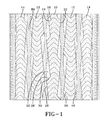
- the center of the tread is provided with a continuously extending rib 10, see FIG. 1. Located on each side of the center rib 10 is at least one additional rib. In the illustrated tread, there are two ribs 12, 14 located on each side of the central rib 10. The ribs 12 adjacent to the center rib 10 are inverse images of the center rib 10. Each rib 14 located outward of the mid-region rib 12 is identical to the center rib 10 and inverse images of the mid-region ribs 12.
- the center rib 10 has sipes 16 extending across the full lateral width of the rib 10.
- the rib 10 has a heavy sipe density, within the range of 2 to 8 sipes per inch (0.78 - 3.15 sipes/cm), with a preferred density of 3 to 7 sipes per inch (1.18 to 2.76 sipes/cm).
- the presence of the rib 10 provides good ground contact for the tread center, while the heavy siping of the rib 10 provides for increased traction as the multiple sipes 16 flex open providing tread edges when the tread contacts the ground.
- the sipes 16 have a non-linear configuration of at least two inclined portions.
- the sipes 16 in FIG. 1 are formed of two inclined portions 18, 20.
- the inclined portions 18, 20 are placed at substantially similar, but oppositely inclined angles to form an inverse V configuration, wherein the apex of the V is located at approximately the equatorial plane EP of the tire.
- the spacing between circumferentially adjacent sipes is constant, but may be varied to permit pitching of the tire for optimization of the noise characteristics of the tire.
- the sides 22, 24 of at least the center rib 10, when viewed from above, has an extended, serrated configuration at the surface of the rib 10 that contacts the ground when the tread is new and not worn.
- Each serration is formed from a laterally oriented edge 26 and an inclined circumferentially extending edge 28; the junction of the two edges 26, 28 forming a serration point 30.
- the serration points 30 on each side of the rib 10 are laterally offset from each other.
- a chamfer 32 Extending from the laterally oriented edge 26 along each side of the rib 10 is a chamfer 32.
- the chamfer 32 extends in a circumferential direction from the laterally oriented edge 26 of the serration to the next circumferentially adjacent serration point 30, along the side of the rib 10.
- the axially inner edge of the chamfer 32 is coincident with the side 22, 24 of the rib 10.
- the chamfers 32 have a greatest width where the chamfer 32 initiates at the laterally oriented edge 26 of the serration.
- the width of the chamfer 32 narrows as the axially outermost edge 32 of the chamfer 32 is substantially parallel to the equatorial plane EP of the tire while the lateral edges 22, 24 of the rib 10 are inclined in the circumferential direction.
- the provision of the chamfers 32 behind the heavily siped rib 10 provides support for the rib 10 as the sipes 16 flex open, strengthening the rib 10 and maintaining good ground contact pressure.
- FIG 2 illustrates a side view of the chamfer 32.
- the chamfer 32 has a maximum width at the laterally oriented edge 26 of the serration, and gradually decreases in width as the chamfer 32 approaches the next adjacent serration point 30.
- the height h of the chamfer 32 gradually decreases, relative to the full tread depth, in the circumferential direction.
- FIG 3 illustrates a variation of the chamfer 32.
- the upper surface of the chamfer 32 is multi-planar. Where the chamfer 32 connects with the laterally oriented edge 26, the surface is defined by a radius of curvature R1 located inward of the upper surface of the chamfer 32. Towards the base of the chamfer 32, the top surface is defined by a radius of curvature R2 located outward of the upper surface of the chamfer 32.
- the chamfer 32 of FIG. 4 is a variation of that of FIG. 3 wherein a flat ledge 34 is employed along the mid-length of the chamfer 32.
- the chamfer 32 forms a tangency R3, R4 to a circle at several locations.
- the top surface of the chamfer 32 has a different multi-planar configuration.
- the top surface of the chamfer 32 slopes downward toward the tread edge, see FIG. 5a.
- the axially outer edge 36 of the chamfer 32 relative to the equatorial plane EP of the tire, gradually increases in height relative to the full tread depth.
- the axially inner edge 38 of the chamfer 32 decreases in height, see FIG. 5b.
- the width of the chamfer 32 decreases, the height, relative to the full tread depth, increases, causing the upper surface of the chamfer 32 to twist.
- the sipes 16 in any of the ribs 10, 12, 14 may extend into any side supporting chamfers 32 present in the rib 10, 12, 14, see FIG. 6.
- the sipes 16 in the chamfers 32 do not open during rotation as there is no contact with the road surface, and the chamfer 32 provides support to the rib 10, 12, 14.
- the uppermost surface of the chamfer 32 slowly becomes part of the ground contacting surface of the tread, the effective rib width increases, and the sipes 16 in the chamfer 32 begins to interact with the remaining tread.
- the sipes 16 in the chamfer 32 act as increased grooving of the tread as the tread depth decreases due to tread wear.
- the laterally oriented edge 26 of each serration is inclined at an angle of equal or less than 90°, but no less than 45° relative to the equatorial plane EP. In the tread of FIG. 1, the laterally oriented edge 26 of each serration is inclined at approximately 45° relative to the equatorial plane EP.
- the laterally oriented edges 26 of each serration on each side 22, 24 of each rib 10, 12, or 14 are inclined as offset mirror images of the each other. Because the chamfers 32 extend from the laterally oriented edges 26, the chamfers 32 on each side 22, 24 of each rib 10, 12, or 14 extend in the same direction.
- the ribs 12 adjacent to the center rib 10 are inverse images of the center rib 10 with the chamfers 32 of the center rib 10 and the mid-region ribs 12 overlapping and extending in opposing directions.
- the overlap of a pair of adjacent chamfers is equal to 5 to 75% of the greatest circumferential length of the chamfers 32.
- the amount of overlap is dictated by the length of the chamfer, and one chamfer 32 may overlap multiple adjacent chamfers 32.
- the overlapping chamfers effectively act to create a wide circumferential groove 88 at the tread surface, while providing support to the rib.
- the laterally oriented edges 26 of adjacent ribs 10, 12 or 12, 14 may be aligned along a straight line, see FIG 8.
- Each laterally oriented edge 26 along one side 22 or 24 of the rib is aligned with the laterally oriented edge 26 on the near side 22 or 24 of the adjacent rib.
- the beginnings of the chamfers 32 are aligned.
- each rib 10, 12, 14 of the tread is directional, but the combination of the ribs 10, 12, 14 yields a non-directional tread configuration.
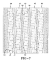
- FIG. 7 illustrates another tread using the same principals of rib construction.
- the laterally oriented edges 26 of at least one rib 40, 42, 44 are inclined in the same direction.
- the circumferentially extending edges 28 of the serration are inclined in the same direction, parallel to each other.
- Each resulting rib 40, 42, 44 is non-directional and are combined to form a ribbed non-directional tire.
- the laterally oriented edges 26 are inclined at an angle of equal or less than 90°.
- the edges 26 are at an angle of about 90° relative to the equatorial plane.
- the chamfers 32 on each side of the rib 40, 42, 44 are inclined in opposing directions.
- the sipes 46 are formed of multiple portions, wherein the first 48 and third 50 portions of the sipe 46 are inclined at substantially equal inclination angles.
- the sipe configuration is selected to correspond with the overall rib configuration, and to maintain or reinforce the directional or non-directional nature of the individual ribs 10, 12, 14.
- the inclination angle of the circumferentially extending edge 28 will also affect the tread configuration.
- the circumferentially extending edge 28 is inclined at angle of approximately 0° to 30° relative to the equatorial plane EP of the tire. When the circumferentially extending edges are substantially parallel to the EP, then the circumferentially adjacent laterally oriented edges 26 are inclined in opposing directions; or else the rib will "walk" across the tread.
- the width of the laterally oriented edges 26 can dictate the width and length of the chamfer 32.
- serrated, chamfered edged ribs may be located on the sides of the equatorial plane EP, forming a circumferentially extending groove at the equatorial plane EP.
- the disclosed rib configuration may also be used in connected with lateral grooves.
- An important aspect of the present invention is the combination of a heavily siped rib with a chamfer extending along the side of the rib to provide support to the heavily siped rib.
- non-direction tread may be identical to that of the directional tread, with permissible variations in accordance with those already discussed.
Landscapes
- Engineering & Computer Science (AREA)
- Mechanical Engineering (AREA)
- Tires In General (AREA)
Applications Claiming Priority (2)
| Application Number | Priority Date | Filing Date | Title |
|---|---|---|---|
| US601936 | 2003-06-23 | ||
| US10/601,936 US7028733B2 (en) | 2003-06-23 | 2003-06-23 | Pneumatic tire having circumferentially extending rib with chamfers |
Publications (2)
| Publication Number | Publication Date |
|---|---|
| EP1498290A1 true EP1498290A1 (de) | 2005-01-19 |
| EP1498290B1 EP1498290B1 (de) | 2006-09-27 |
Family
ID=33477040
Family Applications (1)
| Application Number | Title | Priority Date | Filing Date |
|---|---|---|---|
| EP04102680A Active EP1498290B1 (de) | 2003-06-23 | 2004-06-14 | Reifenlauffläche |
Country Status (5)
| Country | Link |
|---|---|
| US (1) | US7028733B2 (de) |
| EP (1) | EP1498290B1 (de) |
| BR (1) | BRPI0401968B1 (de) |
| CA (1) | CA2465575C (de) |
| DE (1) | DE602004002526T2 (de) |
Cited By (1)
| Publication number | Priority date | Publication date | Assignee | Title |
|---|---|---|---|---|
| EP2732985A1 (de) * | 2012-11-20 | 2014-05-21 | Sumitomo Rubber Industries Limited | Luftreifen |
Families Citing this family (21)
| Publication number | Priority date | Publication date | Assignee | Title |
|---|---|---|---|---|
| US7143798B2 (en) * | 2003-06-23 | 2006-12-05 | The Goodyear Tire & Rubber Company | Pneumatic tire having tread with axially adjacent block chamfer and rib chamfer |
| US6968881B2 (en) * | 2003-06-23 | 2005-11-29 | The Goodyear Tire & Rubber Company | Pneumatic tire including steeply slanted grooves, rib having sipes and blocks having sipes |
| EP1580032B1 (de) * | 2004-03-26 | 2010-10-20 | Continental Reifen Deutschland GmbH | Fahrzeugluftreifen |
| JP5038649B2 (ja) * | 2006-04-18 | 2012-10-03 | 東洋ゴム工業株式会社 | 空気入りタイヤ |
| JP4732379B2 (ja) * | 2007-02-14 | 2011-07-27 | 東洋ゴム工業株式会社 | 空気入りタイヤ |
| US8695655B2 (en) * | 2007-10-15 | 2014-04-15 | The Goodyear Tire & Rubber Company | Tire tread with tread wear indicator |
| KR101532689B1 (ko) * | 2007-11-05 | 2015-06-30 | 피렐리 타이어 소시에떼 퍼 아찌오니 | 공기압 타이어 |
| US20090194211A1 (en) * | 2008-02-01 | 2009-08-06 | John Alan Howald | Tire tread grooves with textured bases |
| US20090194212A1 (en) * | 2008-02-01 | 2009-08-06 | Mark Leonard Bonko | Tire tread discharge grooves with textured bases |
| USD676801S1 (en) | 2011-05-16 | 2013-02-26 | Bridgestone Americas Tire Operations, Llc | Tire tread |
| JP5345721B2 (ja) * | 2012-04-16 | 2013-11-20 | 東洋ゴム工業株式会社 | 空気入りタイヤ |
| JP5664825B2 (ja) * | 2012-06-27 | 2015-02-04 | 横浜ゴム株式会社 | 空気入りタイヤ |
| JP5913247B2 (ja) * | 2013-10-02 | 2016-04-27 | 住友ゴム工業株式会社 | 空気入りタイヤ |
| JP5635170B1 (ja) * | 2013-10-23 | 2014-12-03 | 株式会社ブリヂストン | 空気入りタイヤ |
| FR3012767B1 (fr) * | 2013-11-05 | 2015-10-23 | Michelin & Cie | Bande de roulement comportant un bloc presentant une pluralite d'incisions |
| FR3012768B1 (fr) * | 2013-11-05 | 2016-12-23 | Michelin & Cie | Bande de roulement comportant un bloc presentant une pluralite d'incisions |
| JP5973981B2 (ja) * | 2013-12-04 | 2016-08-23 | 住友ゴム工業株式会社 | 空気入りタイヤ |
| CN108602394B (zh) * | 2016-02-15 | 2021-03-09 | 横滨橡胶株式会社 | 充气轮胎 |
| JP6993203B2 (ja) * | 2017-12-13 | 2022-02-10 | Toyo Tire株式会社 | 空気入りタイヤ |
| WO2019151333A1 (ja) * | 2018-01-30 | 2019-08-08 | 横浜ゴム株式会社 | 空気入りタイヤ |
| CN112334332B (zh) * | 2018-07-03 | 2022-12-27 | 横滨橡胶株式会社 | 充气轮胎 |
Citations (5)
| Publication number | Priority date | Publication date | Assignee | Title |
|---|---|---|---|---|
| EP0882606A2 (de) * | 1997-06-02 | 1998-12-09 | Bridgestone Corporation | Luftreifen |
| EP1075971A1 (de) * | 1999-02-26 | 2001-02-14 | Bridgestone Corporation | Luftreifen |
| EP1090781A2 (de) * | 1999-10-06 | 2001-04-11 | Sumitomo Rubber Industries Limited | Spikeloser Reifen |
| US20010017177A1 (en) * | 2000-02-16 | 2001-08-30 | Bridgestone Corporation | Pneumatic tires |
| EP1197355A2 (de) * | 2000-10-10 | 2002-04-17 | Bridgestone Corporation | Luftreifen |
Family Cites Families (33)
| Publication number | Priority date | Publication date | Assignee | Title |
|---|---|---|---|---|
| DE2455130A1 (de) * | 1974-11-21 | 1976-05-26 | Continental Gummi Werke Ag | Luftreifen fuer kraftfahrzeuge |
| US4641695A (en) * | 1984-07-18 | 1987-02-10 | The Goodyear Tire & Rubber Company | Tread for a pneumatic tire |
| DE3470703D1 (en) * | 1984-08-28 | 1988-06-01 | Goodyear Tire & Rubber | A pneumatic tire |
| JPH0692201B2 (ja) * | 1986-03-14 | 1994-11-16 | 株式会社ブリヂストン | 高速用空気入りラジアルタイヤ |
| GB2192842B (en) * | 1986-06-13 | 1991-01-30 | Bridgestone Corp | Pneumatic tire |
| JPH01215604A (ja) * | 1988-02-23 | 1989-08-29 | Toyo Tire & Rubber Co Ltd | 溝底にサイプを有する重荷重用空気入りラジアルタイヤ |
| US4926919A (en) * | 1988-11-14 | 1990-05-22 | The Goodyear Tire & Rubber Company | Vehicle tire with rib type tread pattern having sipes across the ribs |
| JPH02179508A (ja) * | 1988-12-29 | 1990-07-12 | Yokohama Rubber Co Ltd:The | 空気入りタイヤ |
| JP3332456B2 (ja) * | 1992-03-24 | 2002-10-07 | 株式会社東芝 | 半導体装置の製造方法及び半導体装置 |
| USD358793S (en) * | 1993-04-30 | 1995-05-30 | Bridgestone Corporation | Automobile tire |
| JP3380605B2 (ja) * | 1993-05-20 | 2003-02-24 | 株式会社ブリヂストン | 空気入りタイヤ |
| USD366020S (en) * | 1993-07-30 | 1996-01-09 | Bridgestone Corporation | Automobile tire |
| JP3388902B2 (ja) * | 1994-09-20 | 2003-03-24 | 株式会社ブリヂストン | 空気入りラジアルタイヤ |
| JP3555777B2 (ja) * | 1994-11-22 | 2004-08-18 | 株式会社ブリヂストン | 方向性傾斜溝を有する高運動性能空気入りタイヤ |
| FR2748696B1 (fr) * | 1996-05-20 | 1999-12-31 | Bridgestone Corp | Bandage pneumatique a dessin directionnel asymetrique notamment pour voiture de course |
| JP3542687B2 (ja) * | 1996-06-11 | 2004-07-14 | 株式会社ブリヂストン | 空気入りタイヤ |
| US6213180B1 (en) * | 1997-03-26 | 2001-04-10 | Bridgestone Corporation | Pneumatic radial tire including beveled acute angle corner portions |
| JP3958426B2 (ja) * | 1998-01-14 | 2007-08-15 | 株式会社ブリヂストン | 方向性傾斜溝を備えた乗用車用空気入りラジアル・タイヤ |
| JP3337415B2 (ja) * | 1998-03-04 | 2002-10-21 | 住友ゴム工業株式会社 | 氷上走行に適した空気入りタイヤ |
| USD416836S (en) * | 1998-06-25 | 1999-11-23 | Bridgestone Corporation | Automobile tire |
| USD432057S (en) * | 1999-06-25 | 2000-10-17 | Bridgestone Corporation | Automobile tire |
| USD445730S1 (en) * | 1999-12-27 | 2001-07-31 | Bridgestone Corporation | Automobile tire |
| JP4518639B2 (ja) * | 2000-07-14 | 2010-08-04 | 株式会社ブリヂストン | 空気入りタイヤ |
| JP4136285B2 (ja) * | 2000-07-17 | 2008-08-20 | 東洋ゴム工業株式会社 | 空気入りタイヤ |
| US6520230B1 (en) * | 2000-09-06 | 2003-02-18 | The Goodyear Tire & Rubber Company | Tire with an open tread |
| JP4716551B2 (ja) * | 2000-10-03 | 2011-07-06 | 株式会社ブリヂストン | 冬用空気入りタイヤ |
| USD454833S1 (en) * | 2000-11-08 | 2002-03-26 | Michelin Recherche Et Technique S.A. | Tire tread |
| JP2002240513A (ja) * | 2001-02-20 | 2002-08-28 | Bridgestone Corp | 空気入りタイヤ |
| JP3517404B2 (ja) * | 2001-06-29 | 2004-04-12 | 住友ゴム工業株式会社 | スタッドレスタイヤ |
| EP1412205B1 (de) * | 2001-08-03 | 2006-03-08 | PIRELLI PNEUMATICI Società per Azioni | Insbesondere für schneebedeckten boden geeigneter reifen |
| US6983777B2 (en) * | 2002-10-15 | 2006-01-10 | The Goodyear Tire & Rubber Company | Tire tread with multi-planar chamfers |
| US6968881B2 (en) * | 2003-06-23 | 2005-11-29 | The Goodyear Tire & Rubber Company | Pneumatic tire including steeply slanted grooves, rib having sipes and blocks having sipes |
| US7143798B2 (en) * | 2003-06-23 | 2006-12-05 | The Goodyear Tire & Rubber Company | Pneumatic tire having tread with axially adjacent block chamfer and rib chamfer |
-
2003
- 2003-06-23 US US10/601,936 patent/US7028733B2/en not_active Expired - Lifetime
-
2004
- 2004-04-29 CA CA2465575A patent/CA2465575C/en not_active Expired - Fee Related
- 2004-06-14 DE DE602004002526T patent/DE602004002526T2/de active Active
- 2004-06-14 EP EP04102680A patent/EP1498290B1/de active Active
- 2004-06-16 BR BRPI0401968-7A patent/BRPI0401968B1/pt not_active IP Right Cessation
Patent Citations (5)
| Publication number | Priority date | Publication date | Assignee | Title |
|---|---|---|---|---|
| EP0882606A2 (de) * | 1997-06-02 | 1998-12-09 | Bridgestone Corporation | Luftreifen |
| EP1075971A1 (de) * | 1999-02-26 | 2001-02-14 | Bridgestone Corporation | Luftreifen |
| EP1090781A2 (de) * | 1999-10-06 | 2001-04-11 | Sumitomo Rubber Industries Limited | Spikeloser Reifen |
| US20010017177A1 (en) * | 2000-02-16 | 2001-08-30 | Bridgestone Corporation | Pneumatic tires |
| EP1197355A2 (de) * | 2000-10-10 | 2002-04-17 | Bridgestone Corporation | Luftreifen |
Cited By (3)
| Publication number | Priority date | Publication date | Assignee | Title |
|---|---|---|---|---|
| EP2732985A1 (de) * | 2012-11-20 | 2014-05-21 | Sumitomo Rubber Industries Limited | Luftreifen |
| CN103832220A (zh) * | 2012-11-20 | 2014-06-04 | 住友橡胶工业株式会社 | 充气轮胎 |
| CN103832220B (zh) * | 2012-11-20 | 2017-03-01 | 住友橡胶工业株式会社 | 充气轮胎 |
Also Published As
| Publication number | Publication date |
|---|---|
| BRPI0401968A (pt) | 2005-02-01 |
| US7028733B2 (en) | 2006-04-18 |
| CA2465575A1 (en) | 2004-12-23 |
| US20040256040A1 (en) | 2004-12-23 |
| CA2465575C (en) | 2013-01-29 |
| DE602004002526T2 (de) | 2007-06-06 |
| BRPI0401968B1 (pt) | 2012-09-04 |
| EP1498290B1 (de) | 2006-09-27 |
| DE602004002526D1 (de) | 2006-11-09 |
Similar Documents
| Publication | Publication Date | Title |
|---|---|---|
| EP1498290B1 (de) | Reifenlauffläche | |
| CA2471786C (en) | Tire tread | |
| US8267131B2 (en) | Studless tire | |
| EP0773116B1 (de) | Kraftfahrzeug-Luftreifen mit einem Laufflächenprofil besonders geeignet zum Laufen auf schneebedeckten Strassenoberflächen | |
| US6983777B2 (en) | Tire tread with multi-planar chamfers | |
| RU2521033C2 (ru) | Шина для автомобиля | |
| US6609548B2 (en) | Asymmetrical vehicle tire with balanced wet and dry performance | |
| EP0904960B1 (de) | Spikeloser luftreifen | |
| EP0069464A2 (de) | Luftreifen Lauffläche | |
| EP3017964A1 (de) | Verbesserte lauffläche für einen winterreifen | |
| US20080271827A1 (en) | Pnuematic tire | |
| JPS62214004A (ja) | 高速用空気入りラジアルタイヤ | |
| US5746849A (en) | Tire tread including tie bar | |
| US20080271826A1 (en) | Pnuematic tire | |
| CA2471995C (en) | Tire tread | |
| JPH07121645B2 (ja) | 空気入りタイヤ | |
| EP1034945A1 (de) | Luftreifen | |
| EP1093939B1 (de) | Reifenlauffläche für Strassen/geländegängige Fahrzeuge | |
| JP3113388B2 (ja) | 空気入りタイヤ | |
| EP3332990B1 (de) | Laufstreifen für einen winterreifen | |
| JPH09188110A (ja) | 重荷重用空気入りラジアルタイヤ | |
| JP2004338628A (ja) | 空気入りタイヤ | |
| EP3995324B1 (de) | Reifen mit einer oder mehreren aussparungen in den seitlichen rillen von mindestens einem schulterteil | |
| JP2866636B2 (ja) | 重荷重用空気入りタイヤ | |
| JPH0547681Y2 (de) |
Legal Events
| Date | Code | Title | Description |
|---|---|---|---|
| PUAI | Public reference made under article 153(3) epc to a published international application that has entered the european phase |
Free format text: ORIGINAL CODE: 0009012 |
|
| AK | Designated contracting states |
Kind code of ref document: A1 Designated state(s): AT BE BG CH CY CZ DE DK EE ES FI FR GB GR HU IE IT LI LU MC NL PL PT RO SE SI SK TR |
|
| AX | Request for extension of the european patent |
Extension state: AL HR LT LV MK |
|
| 17P | Request for examination filed |
Effective date: 20050719 |
|
| AKX | Designation fees paid |
Designated state(s): DE FR GB IT |
|
| GRAP | Despatch of communication of intention to grant a patent |
Free format text: ORIGINAL CODE: EPIDOSNIGR1 |
|
| GRAS | Grant fee paid |
Free format text: ORIGINAL CODE: EPIDOSNIGR3 |
|
| GRAA | (expected) grant |
Free format text: ORIGINAL CODE: 0009210 |
|
| AK | Designated contracting states |
Kind code of ref document: B1 Designated state(s): DE FR GB IT |
|
| PG25 | Lapsed in a contracting state [announced via postgrant information from national office to epo] |
Ref country code: IT Free format text: LAPSE BECAUSE OF FAILURE TO SUBMIT A TRANSLATION OF THE DESCRIPTION OR TO PAY THE FEE WITHIN THE PRESCRIBED TIME-LIMIT;WARNING: LAPSES OF ITALIAN PATENTS WITH EFFECTIVE DATE BEFORE 2007 MAY HAVE OCCURRED AT ANY TIME BEFORE 2007. THE CORRECT EFFECTIVE DATE MAY BE DIFFERENT FROM THE ONE RECORDED. Effective date: 20060927 |
|
| REG | Reference to a national code |
Ref country code: GB Ref legal event code: FG4D |
|
| REF | Corresponds to: |
Ref document number: 602004002526 Country of ref document: DE Date of ref document: 20061109 Kind code of ref document: P |
|
| ET | Fr: translation filed | ||
| PLBE | No opposition filed within time limit |
Free format text: ORIGINAL CODE: 0009261 |
|
| STAA | Information on the status of an ep patent application or granted ep patent |
Free format text: STATUS: NO OPPOSITION FILED WITHIN TIME LIMIT |
|
| 26N | No opposition filed |
Effective date: 20070628 |
|
| PGRI | Patent reinstated in contracting state [announced from national office to epo] |
Ref country code: IT Effective date: 20080801 |
|
| PGFP | Annual fee paid to national office [announced via postgrant information from national office to epo] |
Ref country code: GB Payment date: 20080506 Year of fee payment: 5 |
|
| GBPC | Gb: european patent ceased through non-payment of renewal fee |
Effective date: 20090614 |
|
| PG25 | Lapsed in a contracting state [announced via postgrant information from national office to epo] |
Ref country code: GB Free format text: LAPSE BECAUSE OF NON-PAYMENT OF DUE FEES Effective date: 20090614 |
|
| REG | Reference to a national code |
Ref country code: FR Ref legal event code: PLFP Year of fee payment: 13 |
|
| REG | Reference to a national code |
Ref country code: FR Ref legal event code: PLFP Year of fee payment: 14 |
|
| REG | Reference to a national code |
Ref country code: FR Ref legal event code: PLFP Year of fee payment: 15 |
|
| PGFP | Annual fee paid to national office [announced via postgrant information from national office to epo] |
Ref country code: DE Payment date: 20180530 Year of fee payment: 15 |
|
| PGFP | Annual fee paid to national office [announced via postgrant information from national office to epo] |
Ref country code: IT Payment date: 20180625 Year of fee payment: 15 |
|
| REG | Reference to a national code |
Ref country code: DE Ref legal event code: R119 Ref document number: 602004002526 Country of ref document: DE |
|
| PG25 | Lapsed in a contracting state [announced via postgrant information from national office to epo] |
Ref country code: IT Free format text: LAPSE BECAUSE OF FAILURE TO SUBMIT A TRANSLATION OF THE DESCRIPTION OR TO PAY THE FEE WITHIN THE PRESCRIBED TIME-LIMIT Effective date: 20190614 Ref country code: DE Free format text: LAPSE BECAUSE OF NON-PAYMENT OF DUE FEES Effective date: 20200101 |
|
| PGFP | Annual fee paid to national office [announced via postgrant information from national office to epo] |
Ref country code: FR Payment date: 20220408 Year of fee payment: 19 |