EP1498286A1 - Transportrad mit Bremse für Wagen - Google Patents
Transportrad mit Bremse für Wagen Download PDFInfo
- Publication number
- EP1498286A1 EP1498286A1 EP03468005A EP03468005A EP1498286A1 EP 1498286 A1 EP1498286 A1 EP 1498286A1 EP 03468005 A EP03468005 A EP 03468005A EP 03468005 A EP03468005 A EP 03468005A EP 1498286 A1 EP1498286 A1 EP 1498286A1
- Authority
- EP
- European Patent Office
- Prior art keywords
- brake
- pedal
- wheel
- fork
- transverse
- Prior art date
- Legal status (The legal status is an assumption and is not a legal conclusion. Google has not performed a legal analysis and makes no representation as to the accuracy of the status listed.)
- Granted
Links
Images


Classifications
-
- B—PERFORMING OPERATIONS; TRANSPORTING
- B60—VEHICLES IN GENERAL
- B60B—VEHICLE WHEELS; CASTORS; AXLES FOR WHEELS OR CASTORS; INCREASING WHEEL ADHESION
- B60B33/00—Castors in general ; Anti-clogging castors
- B60B33/0002—Castors in general ; Anti-clogging castors assembling to the object, e.g. furniture
- B60B33/0015—Castors in general ; Anti-clogging castors assembling to the object, e.g. furniture characterised by adaptations made to castor
- B60B33/0018—Castors in general ; Anti-clogging castors assembling to the object, e.g. furniture characterised by adaptations made to castor in the form of a flat mounting plate
-
- B—PERFORMING OPERATIONS; TRANSPORTING
- B60—VEHICLES IN GENERAL
- B60B—VEHICLE WHEELS; CASTORS; AXLES FOR WHEELS OR CASTORS; INCREASING WHEEL ADHESION
- B60B33/00—Castors in general ; Anti-clogging castors
- B60B33/0036—Castors in general ; Anti-clogging castors characterised by type of wheels
- B60B33/0039—Single wheels
-
- B—PERFORMING OPERATIONS; TRANSPORTING
- B60—VEHICLES IN GENERAL
- B60B—VEHICLE WHEELS; CASTORS; AXLES FOR WHEELS OR CASTORS; INCREASING WHEEL ADHESION
- B60B33/00—Castors in general ; Anti-clogging castors
- B60B33/0047—Castors in general ; Anti-clogging castors characterised by details of the rolling axle
- B60B33/0049—Castors in general ; Anti-clogging castors characterised by details of the rolling axle the rolling axle being horizontal
-
- B—PERFORMING OPERATIONS; TRANSPORTING
- B60—VEHICLES IN GENERAL
- B60B—VEHICLE WHEELS; CASTORS; AXLES FOR WHEELS OR CASTORS; INCREASING WHEEL ADHESION
- B60B33/00—Castors in general ; Anti-clogging castors
- B60B33/0047—Castors in general ; Anti-clogging castors characterised by details of the rolling axle
- B60B33/0057—Castors in general ; Anti-clogging castors characterised by details of the rolling axle the rolling axle being offset from swivel axis
-
- B—PERFORMING OPERATIONS; TRANSPORTING
- B60—VEHICLES IN GENERAL
- B60B—VEHICLE WHEELS; CASTORS; AXLES FOR WHEELS OR CASTORS; INCREASING WHEEL ADHESION
- B60B33/00—Castors in general ; Anti-clogging castors
- B60B33/006—Castors in general ; Anti-clogging castors characterised by details of the swivel mechanism
- B60B33/0065—Castors in general ; Anti-clogging castors characterised by details of the swivel mechanism characterised by details of the swivel axis
- B60B33/0068—Castors in general ; Anti-clogging castors characterised by details of the swivel mechanism characterised by details of the swivel axis the swivel axis being vertical
-
- B—PERFORMING OPERATIONS; TRANSPORTING
- B60—VEHICLES IN GENERAL
- B60B—VEHICLE WHEELS; CASTORS; AXLES FOR WHEELS OR CASTORS; INCREASING WHEEL ADHESION
- B60B33/00—Castors in general ; Anti-clogging castors
- B60B33/006—Castors in general ; Anti-clogging castors characterised by details of the swivel mechanism
- B60B33/0065—Castors in general ; Anti-clogging castors characterised by details of the swivel mechanism characterised by details of the swivel axis
- B60B33/0073—Castors in general ; Anti-clogging castors characterised by details of the swivel mechanism characterised by details of the swivel axis the swivel axis being symmetrical to wheel or wheels
-
- B—PERFORMING OPERATIONS; TRANSPORTING
- B60—VEHICLES IN GENERAL
- B60B—VEHICLE WHEELS; CASTORS; AXLES FOR WHEELS OR CASTORS; INCREASING WHEEL ADHESION
- B60B33/00—Castors in general ; Anti-clogging castors
- B60B33/0078—Castors in general ; Anti-clogging castors characterised by details of the wheel braking mechanism
- B60B33/0081—Castors in general ; Anti-clogging castors characterised by details of the wheel braking mechanism acting on tyre tread
-
- B—PERFORMING OPERATIONS; TRANSPORTING
- B60—VEHICLES IN GENERAL
- B60B—VEHICLE WHEELS; CASTORS; AXLES FOR WHEELS OR CASTORS; INCREASING WHEEL ADHESION
- B60B33/00—Castors in general ; Anti-clogging castors
- B60B33/02—Castors in general ; Anti-clogging castors with disengageable swivel action, i.e. comprising a swivel locking mechanism
- B60B33/021—Castors in general ; Anti-clogging castors with disengageable swivel action, i.e. comprising a swivel locking mechanism combined with braking of castor wheel
-
- B—PERFORMING OPERATIONS; TRANSPORTING
- B60—VEHICLES IN GENERAL
- B60B—VEHICLE WHEELS; CASTORS; AXLES FOR WHEELS OR CASTORS; INCREASING WHEEL ADHESION
- B60B33/00—Castors in general ; Anti-clogging castors
- B60B33/02—Castors in general ; Anti-clogging castors with disengageable swivel action, i.e. comprising a swivel locking mechanism
- B60B33/025—Castors in general ; Anti-clogging castors with disengageable swivel action, i.e. comprising a swivel locking mechanism by using form-fit, e.g. front teeth
Definitions
- the subject of the invention is a transport wheel with brake for cars.
- the technical problem solved by this invention is to provide a to create such a brake of a transport wheel for cars that their brake and Release elements regardless of the position of the wheel under the carriage with the foot be reached, the process and the necessary brake and Release force on all elements will be the same for braking and release, and that simultaneously with the braking or releasing a blocking or Unlocking the swinging of the wheel fork about an axis perpendicular to the Plane of the plate by which the wheel is attached to the moving object, runs, is performed.
- Previously known brakes for wagon wheels are equipped with a foot lever, through which a brake lever, which presses against the tread of the wheel actuated becomes. The release takes place by moving the foot lever in the opposite direction, usually upwards. If such a wheel on a car or the like it often happens that the foot pedal is not accessible. therefore the cart must be moved to turn the wheel in the direction that the Reaching the foot lever allows.
- Another embodiment of the brakes includes two in different directions oriented foot pedal. This results in two ways to the pedal to reach. However, their mutual connection is based on the balance principle, why is not clearly specified in which direction the brake or Release lever is to be moved, which additionally loads the user.
- the illustrated technical problem is caused by the brake according to the invention solved, which is characterized in that it has three pedals, one Pedal on one side of the wheel next to the tread and the other two Pedals on the opposite side of the wheel, on its flanks.
- the others Two pedals are fixed to each other and have the first pedal Contact via a lever that enables itself while pressing any Pedals to brake or release the other two pedals in the same Move direction. So all three pedals are always in the same position and in the same function. If any pedal for braking after was pressed down, then the wheel by the upward operation of a any pedal that is best accessible at the moment, solved.
- the transport wheel with brake for cars consists of a mounting plate 1, under which a fork 2 with a wheel 3 is rotatably mounted.
- a camp 4 which the Fastening plate 1 and the fork 2 connects, is in the sense of an axial Run ball bearing, the connecting ring 5 on the side of the fork 2 with a serrated ring 6 is executed.
- the fork 2 is a brake 7, whose Brake shoe 8 acts on the running surface 9 of the wheel 3, pivotally mounted.
- On a transverse pin 10 is a spring 11, the brake 7 in the release position urges, arranged.
- the two pedal legs 13 extend on the flanks of the wheel 3 and with his transverse leg 14, which connects the pedal leg 13, under a cross member 15 of the fork 2 is mounted leaning, so that it is around his Transverse edge 16 is pivotable.
- a located on the fork 2 pin 17 passes through holes 18 in the Pedal legs 13 of the pedal 12, wherein the cross section of the holes 18 is greater than that of the pin 17, whereby the holes 18 a limitation of the pivoting allow the pedal 12 to its transverse edge 16.
- a simple brake pedal 22 pivotally mounted, the end 23 away from the Rad 3, but protrudes freely in its longitudinal plane and to operate with the Foot is provided during braking or release.
- a mutual end 24 of the Pedals 22 on the bolt 21 is in addition to a free end 25 of the brake 7 at the side of the brake shoe 8 rotatably mounted.
- this storage 26th designed as a positive connection, namely as a transverse slot 27th on the brake 7 and a curved edge 28 located therein at the free end 24th of the pedal 22 are on the lever 19, the bolts 17, 20, 21 in the Corners of an apparent triangle.
- the brake 7 is supported on the spring 11, so that their gege workedes end 31 with a prong 32 free on the serrated ring 6 of the ring 5 is located.
- the pedal 12 or 22 is pivoted in the braking position of the wheel 3, snaps at the Acting on the free end 25 of the brake 7, the mutual end 31 of Brake 7 with the tine 32 in the serrated ring 6 of the ring 5 a.
- the brake works in such a way that when depressing the foot on the free End 23 of the simple pedal 22 this in the storage 26 on the brake 7th pivots, which, supported by the spring 11, with their mutual end 31 in the serrated ring 6 of the connecting ring 5 snaps, at the same time the Lever 19 because of the connection with the brake 7 in the bolt 21 on the bolt 17 pivots.
- the lever 19 and the double pedal 12 by the Bolt 20 are connected to each other, pivots the double pedal 12 also down to its transverse edge 16 of the transverse leg 14, which under the cross member 15 of the fork 2 is applied, and is also in the braking position without you it would have pressed with the foot.
- the simple pedal 22nd and the brake 7 connects, approaches during the downward pivoting of simple pedal 22 in the braking direction, the brake 7 of the tread 9 of the Rades 3 and brakes it.
Landscapes
- Engineering & Computer Science (AREA)
- Mechanical Engineering (AREA)
- Braking Arrangements (AREA)
- Handcart (AREA)
Abstract
Description
- Fig. 1
- einen teilweisen Längsschnitt des erfindungsgemäßen Rades für Wagen mit Bremse im gelösten, d.h. Fahrzustand,
- Fig. 2
- das Gleiche, doch im Bremszustand,
- Fig. 3
- einen teilweisen Längsschnitt des erfindungsgemäßen Rades im vergrösserten Maßstab.
- Fig. 5
- eine Aufsicht des erfindungsgemäßen Rades mit Bremse für Wagen,
- Fig. 4
- eine Untenansicht auf das Gleiche, jedoch ohne Rad,
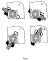
- Fig. 6
- Aufsichten der erfindungsgemäßen Räder in verschiedenen Verschiebungen in Bezug auf die Wagenecke.
Claims (6)
- Transportrad mit Bremse für Wagen bestehend aus einer Befestigungsplatte (1), unter welcher eine Gabel (2) mit einem Rad (3) drehbar gelagert ist, wobei sich in der Gabel (2) eine schwenkbar gelagerte Bremse (7), deren Bremsbacke (8) auf die Lauffläche (9) des Rades (3) einwirkt, befindet, dadurch gekennzeichnet, dass in der Gabel (2) ein zweifaches Bremspedal (12), dessen Pedalschenkel (13) an den Flanken des Rades (3) verlaufen, und ein einfaches, in der Gegenrichtung orientiertes Pedal (22), das mit dem zweifachen Pedal (12) durch einen Hebel (1) und ebenso mit der Bremse (7), die gleichzeitig zum Bremsen auch das Schwenken der Gabel (2) um die senkrecht zur Befestigungsplatte (1) liegenden Achse blockiert, verbunden ist, angeordnet sind, wobei die beiden Pedale (12 und 22) wegen deren Verbindung gleichzeitig und gleich funktionieren, ungeachtet dessen, welches Pedal man mit dem Fuß betätigt.
- Transportrad mit Bremse für Wagen nach Anspruch 1, dadurch gekennzeichnet, dass das zweifache Pedal (12) mit seinem Querschenkel (14), der die Pedalschenkel (13) verbindet, unter einem Querteil (15) der Gabel (2) anlehnbar gelagert ist, so dass es um einen Querrand (16) des Querschenkels (14) schwenkbar ist, wobei ein sich in der Gabel (2) befindender Bolzen (17) durch zwei Löcher (18) in den Pedalschenkeln (13) des zweifachen Pedals (12) verläuft und der Querschnitt der Löcher (18) größer als der des Bolzens (17) ist, wodurch die Löcher (18) eine Begrenzung der Schwenkung des Pedals (12) um seinen Querrand (16) ermöglichen.
- Transportrad mit Bremse für Wagen nach Ansprüchen 1 und 2, dadurch gekennzeichnet, dass unter dem Querschenkel (14) des zweifachen Pedals (12) ein Hebel (19) auf einem Querbolzen (17) schwenkbar gelagert ist und zugleich dadurch ein in den Pedalschenkeln (13) schwenkbar gelagerter Bolzen (20) verläuft, und gleichzeitig am Gegenende des Hebels (19), vom Bolzen (17) her gesehen, auf dem Bolzen (21) das einfache Bremspedal (22) schwenkbar gelagert ist, dessen Ende (24) am Bolzen (21) zusätzlich mit einer Lagerung (26) an einem freien Ende (25) der Bremse (7) an der Seite der Bremsbacke (8) ausgeführt ist.
- Transportrad mit Bremse für Wagen nach Ansprüchen 1 bis 3, dadurch gekennzeichnet, dass die Lagerung (26) als eine formschlüssige Verbindung ausgeführt ist, und zwar als ein Querschlitz (27) auf der Bremse (7) und eine darin liegende gebogene Fahne (28) am freien Ende (24) des Pedals (22).
- Transportrad mit Bremse für Wagen nach Ansprüchen 1 bis 4, dadurch gekennzeichnet, dass am Querbolzen (10) eine Feder (11) angebracht ist, die die Bremse (7) in die Löselage drängt.
- Transportrad mit Bremse für Wagen nach Ansprüchen 1 bis 5, dadurch gekennzeichnet, dass die Bremse (7) gestützt an die Feder (11) so liegt, dass ihr gegeseitiges Ende (31) mit einer Zacke (32) frei an einem gezackten Ring (6) eines Verbindungsringes (5) liegt, wobei bei der Schwenkung irgendeines Pedals (12 oder 22) in die Bremslage des Rades (3) beim Einwirken auf das freie Ende (25) der Bremse (7) das gegenseitige Ende (31) der Bremse (7) mit der Zacke (32) in den gezackten Ring (6) des Verbindungsringes (5) einschnappt.
Priority Applications (3)
| Application Number | Priority Date | Filing Date | Title |
|---|---|---|---|
| AT03468005T ATE394249T1 (de) | 2003-07-16 | 2003-07-16 | Transportrad mit bremse für wagen |
| DE50309783T DE50309783D1 (de) | 2003-07-16 | 2003-07-16 | Transportrad mit Bremse für Wagen |
| EP03468005A EP1498286B1 (de) | 2003-07-16 | 2003-07-16 | Transportrad mit Bremse für Wagen |
Applications Claiming Priority (1)
| Application Number | Priority Date | Filing Date | Title |
|---|---|---|---|
| EP03468005A EP1498286B1 (de) | 2003-07-16 | 2003-07-16 | Transportrad mit Bremse für Wagen |
Publications (2)
| Publication Number | Publication Date |
|---|---|
| EP1498286A1 true EP1498286A1 (de) | 2005-01-19 |
| EP1498286B1 EP1498286B1 (de) | 2008-05-07 |
Family
ID=33462303
Family Applications (1)
| Application Number | Title | Priority Date | Filing Date |
|---|---|---|---|
| EP03468005A Expired - Lifetime EP1498286B1 (de) | 2003-07-16 | 2003-07-16 | Transportrad mit Bremse für Wagen |
Country Status (3)
| Country | Link |
|---|---|
| EP (1) | EP1498286B1 (de) |
| AT (1) | ATE394249T1 (de) |
| DE (1) | DE50309783D1 (de) |
Citations (3)
| Publication number | Priority date | Publication date | Assignee | Title |
|---|---|---|---|---|
| GB926202A (en) * | 1961-02-24 | 1963-05-15 | Ml Aviation Co Ltd | Improvements relating to wheel brakes |
| DE1580179A1 (de) * | 1967-01-07 | 1971-12-23 | Schulte & Co Kugelfab | Feststellvorrichtung fuer Lenkrollen |
| US4349937A (en) * | 1980-07-11 | 1982-09-21 | Stewart-Warner Corporation | Caster assembly with swivel lock and brake |
-
2003
- 2003-07-16 DE DE50309783T patent/DE50309783D1/de not_active Expired - Lifetime
- 2003-07-16 AT AT03468005T patent/ATE394249T1/de not_active IP Right Cessation
- 2003-07-16 EP EP03468005A patent/EP1498286B1/de not_active Expired - Lifetime
Patent Citations (3)
| Publication number | Priority date | Publication date | Assignee | Title |
|---|---|---|---|---|
| GB926202A (en) * | 1961-02-24 | 1963-05-15 | Ml Aviation Co Ltd | Improvements relating to wheel brakes |
| DE1580179A1 (de) * | 1967-01-07 | 1971-12-23 | Schulte & Co Kugelfab | Feststellvorrichtung fuer Lenkrollen |
| US4349937A (en) * | 1980-07-11 | 1982-09-21 | Stewart-Warner Corporation | Caster assembly with swivel lock and brake |
Also Published As
| Publication number | Publication date |
|---|---|
| ATE394249T1 (de) | 2008-05-15 |
| EP1498286B1 (de) | 2008-05-07 |
| DE50309783D1 (de) | 2008-06-19 |
Similar Documents
| Publication | Publication Date | Title |
|---|---|---|
| EP0449029B1 (de) | Deichselgeführtes elektrisches Flurförderzeug | |
| EP1590224A1 (de) | Von hand bewegbarer transportwagen | |
| DE60315951T2 (de) | Radhubmechanismus | |
| DE3028373C2 (de) | Lenkrolle für ein Fahrwerk mit einer Bremsvorrichtung | |
| DE69818400T2 (de) | Hilfeeinrichtung zur Betätigung eines Hebels | |
| DE2508950A1 (de) | Vorrichtung zum blockieren der fahrrollen von wagen, insbesondere von servierwagen | |
| DE102015102150A1 (de) | Rollwagen für den Warentransport | |
| DE69423644T2 (de) | Einkaufswagen mit lenkrolle mit feststelleinrichtung | |
| EP1498286B1 (de) | Transportrad mit Bremse für Wagen | |
| DE4008855A1 (de) | Fahrwerk fuer transportbehaelter, apparate o. dgl. | |
| DE4221541C2 (de) | Gebremste Lenkrolle | |
| DE69105723T2 (de) | Achssystem in einem transportfahrzeug. | |
| AT524641B1 (de) | Bremsanordnung für eine Gleitbrettbindung | |
| DE10259448A1 (de) | Lenkrolle | |
| DE102007011701A1 (de) | Verfahrbare Transportvorrichtung und Anordnung mit zwei solchen Transportvorrichtungen | |
| DE3541176A1 (de) | Treppengleitender handkarren | |
| DE2257300A1 (de) | Sperrvorrichtung fuer laufraeder | |
| DE10065992B4 (de) | Rollerboard | |
| DE602004010503T2 (de) | Pedalanordnung | |
| DE2709253A1 (de) | Selbstsperrende ruecklaufsperre insbesondere fuer fahrzeuge | |
| DE2336691A1 (de) | Handbewegtes flurfoerderzeug | |
| DE1939646A1 (de) | Scheibenbremse mit mechanischer Betaetigungsvorrichtung | |
| DE102016116169B4 (de) | Bremsvorrichtungsbausatz und Bremsvorrichtung für ein Rollbrett sowie Rollbrett | |
| DE2127723A1 (de) | Gabelhubwagen | |
| DE29914253U1 (de) | Mitfahrplattform für Kinderwagen |
Legal Events
| Date | Code | Title | Description |
|---|---|---|---|
| PUAI | Public reference made under article 153(3) epc to a published international application that has entered the european phase |
Free format text: ORIGINAL CODE: 0009012 |
|
| AK | Designated contracting states |
Kind code of ref document: A1 Designated state(s): AT BE BG CH CY CZ DE DK EE ES FI FR GB GR HU IE IT LI LU MC NL PT RO SE SI SK TR |
|
| AX | Request for extension of the european patent |
Extension state: AL LT LV MK |
|
| 17P | Request for examination filed |
Effective date: 20050701 |
|
| AKX | Designation fees paid |
Designated state(s): AT BE BG CH CY CZ DE DK EE ES FI FR GB GR HU IE IT LI LU MC NL PT RO SE SI SK TR |
|
| 17Q | First examination report despatched |
Effective date: 20070502 |
|
| GRAP | Despatch of communication of intention to grant a patent |
Free format text: ORIGINAL CODE: EPIDOSNIGR1 |
|
| GRAS | Grant fee paid |
Free format text: ORIGINAL CODE: EPIDOSNIGR3 |
|
| GRAA | (expected) grant |
Free format text: ORIGINAL CODE: 0009210 |
|
| AK | Designated contracting states |
Kind code of ref document: B1 Designated state(s): AT BE BG CH CY CZ DE DK EE ES FI FR GB GR HU IE IT LI LU MC NL PT RO SE SI SK TR |
|
| REG | Reference to a national code |
Ref country code: GB Ref legal event code: FG4D Free format text: NOT ENGLISH |
|
| REG | Reference to a national code |
Ref country code: CH Ref legal event code: EP |
|
| REG | Reference to a national code |
Ref country code: IE Ref legal event code: FG4D Free format text: LANGUAGE OF EP DOCUMENT: GERMAN |
|
| REF | Corresponds to: |
Ref document number: 50309783 Country of ref document: DE Date of ref document: 20080619 Kind code of ref document: P |
|
| PG25 | Lapsed in a contracting state [announced via postgrant information from national office to epo] |
Ref country code: SI Free format text: LAPSE BECAUSE OF FAILURE TO SUBMIT A TRANSLATION OF THE DESCRIPTION OR TO PAY THE FEE WITHIN THE PRESCRIBED TIME-LIMIT Effective date: 20080507 |
|
| PG25 | Lapsed in a contracting state [announced via postgrant information from national office to epo] |
Ref country code: ES Free format text: LAPSE BECAUSE OF FAILURE TO SUBMIT A TRANSLATION OF THE DESCRIPTION OR TO PAY THE FEE WITHIN THE PRESCRIBED TIME-LIMIT Effective date: 20080818 Ref country code: NL Free format text: LAPSE BECAUSE OF FAILURE TO SUBMIT A TRANSLATION OF THE DESCRIPTION OR TO PAY THE FEE WITHIN THE PRESCRIBED TIME-LIMIT Effective date: 20080507 Ref country code: FI Free format text: LAPSE BECAUSE OF FAILURE TO SUBMIT A TRANSLATION OF THE DESCRIPTION OR TO PAY THE FEE WITHIN THE PRESCRIBED TIME-LIMIT Effective date: 20080507 |
|
| NLV1 | Nl: lapsed or annulled due to failure to fulfill the requirements of art. 29p and 29m of the patents act | ||
| REG | Reference to a national code |
Ref country code: IE Ref legal event code: FD4D |
|
| PG25 | Lapsed in a contracting state [announced via postgrant information from national office to epo] |
Ref country code: IE Free format text: LAPSE BECAUSE OF FAILURE TO SUBMIT A TRANSLATION OF THE DESCRIPTION OR TO PAY THE FEE WITHIN THE PRESCRIBED TIME-LIMIT Effective date: 20080507 Ref country code: DK Free format text: LAPSE BECAUSE OF FAILURE TO SUBMIT A TRANSLATION OF THE DESCRIPTION OR TO PAY THE FEE WITHIN THE PRESCRIBED TIME-LIMIT Effective date: 20080507 Ref country code: CZ Free format text: LAPSE BECAUSE OF FAILURE TO SUBMIT A TRANSLATION OF THE DESCRIPTION OR TO PAY THE FEE WITHIN THE PRESCRIBED TIME-LIMIT Effective date: 20080507 Ref country code: SE Free format text: LAPSE BECAUSE OF FAILURE TO SUBMIT A TRANSLATION OF THE DESCRIPTION OR TO PAY THE FEE WITHIN THE PRESCRIBED TIME-LIMIT Effective date: 20080807 Ref country code: PT Free format text: LAPSE BECAUSE OF FAILURE TO SUBMIT A TRANSLATION OF THE DESCRIPTION OR TO PAY THE FEE WITHIN THE PRESCRIBED TIME-LIMIT Effective date: 20081007 |
|
| PG25 | Lapsed in a contracting state [announced via postgrant information from national office to epo] |
Ref country code: RO Free format text: LAPSE BECAUSE OF FAILURE TO SUBMIT A TRANSLATION OF THE DESCRIPTION OR TO PAY THE FEE WITHIN THE PRESCRIBED TIME-LIMIT Effective date: 20080507 Ref country code: SK Free format text: LAPSE BECAUSE OF FAILURE TO SUBMIT A TRANSLATION OF THE DESCRIPTION OR TO PAY THE FEE WITHIN THE PRESCRIBED TIME-LIMIT Effective date: 20080507 |
|
| REG | Reference to a national code |
Ref country code: CH Ref legal event code: PL |
|
| PLBE | No opposition filed within time limit |
Free format text: ORIGINAL CODE: 0009261 |
|
| STAA | Information on the status of an ep patent application or granted ep patent |
Free format text: STATUS: NO OPPOSITION FILED WITHIN TIME LIMIT |
|
| PG25 | Lapsed in a contracting state [announced via postgrant information from national office to epo] |
Ref country code: MC Free format text: LAPSE BECAUSE OF NON-PAYMENT OF DUE FEES Effective date: 20080731 |
|
| 26N | No opposition filed |
Effective date: 20090210 |
|
| GBPC | Gb: european patent ceased through non-payment of renewal fee |
Effective date: 20080807 |
|
| PG25 | Lapsed in a contracting state [announced via postgrant information from national office to epo] |
Ref country code: BG Free format text: LAPSE BECAUSE OF FAILURE TO SUBMIT A TRANSLATION OF THE DESCRIPTION OR TO PAY THE FEE WITHIN THE PRESCRIBED TIME-LIMIT Effective date: 20080807 Ref country code: EE Free format text: LAPSE BECAUSE OF FAILURE TO SUBMIT A TRANSLATION OF THE DESCRIPTION OR TO PAY THE FEE WITHIN THE PRESCRIBED TIME-LIMIT Effective date: 20080507 |
|
| REG | Reference to a national code |
Ref country code: FR Ref legal event code: ST Effective date: 20090331 |
|
| PG25 | Lapsed in a contracting state [announced via postgrant information from national office to epo] |
Ref country code: LI Free format text: LAPSE BECAUSE OF NON-PAYMENT OF DUE FEES Effective date: 20080731 Ref country code: CH Free format text: LAPSE BECAUSE OF NON-PAYMENT OF DUE FEES Effective date: 20080731 |
|
| PG25 | Lapsed in a contracting state [announced via postgrant information from national office to epo] |
Ref country code: FR Free format text: LAPSE BECAUSE OF NON-PAYMENT OF DUE FEES Effective date: 20080731 |
|
| PG25 | Lapsed in a contracting state [announced via postgrant information from national office to epo] |
Ref country code: AT Free format text: LAPSE BECAUSE OF NON-PAYMENT OF DUE FEES Effective date: 20080716 |
|
| PG25 | Lapsed in a contracting state [announced via postgrant information from national office to epo] |
Ref country code: GB Free format text: LAPSE BECAUSE OF NON-PAYMENT OF DUE FEES Effective date: 20080807 |
|
| PG25 | Lapsed in a contracting state [announced via postgrant information from national office to epo] |
Ref country code: BE Free format text: LAPSE BECAUSE OF NON-PAYMENT OF DUE FEES Effective date: 20080731 Ref country code: HU Free format text: LAPSE BECAUSE OF FAILURE TO SUBMIT A TRANSLATION OF THE DESCRIPTION OR TO PAY THE FEE WITHIN THE PRESCRIBED TIME-LIMIT Effective date: 20081108 Ref country code: LU Free format text: LAPSE BECAUSE OF NON-PAYMENT OF DUE FEES Effective date: 20080716 Ref country code: CY Free format text: LAPSE BECAUSE OF FAILURE TO SUBMIT A TRANSLATION OF THE DESCRIPTION OR TO PAY THE FEE WITHIN THE PRESCRIBED TIME-LIMIT Effective date: 20080507 |
|
| PG25 | Lapsed in a contracting state [announced via postgrant information from national office to epo] |
Ref country code: TR Free format text: LAPSE BECAUSE OF FAILURE TO SUBMIT A TRANSLATION OF THE DESCRIPTION OR TO PAY THE FEE WITHIN THE PRESCRIBED TIME-LIMIT Effective date: 20080507 |
|
| PG25 | Lapsed in a contracting state [announced via postgrant information from national office to epo] |
Ref country code: GR Free format text: LAPSE BECAUSE OF FAILURE TO SUBMIT A TRANSLATION OF THE DESCRIPTION OR TO PAY THE FEE WITHIN THE PRESCRIBED TIME-LIMIT Effective date: 20080808 |
|
| PGFP | Annual fee paid to national office [announced via postgrant information from national office to epo] |
Ref country code: IT Payment date: 20100728 Year of fee payment: 8 |
|
| PGFP | Annual fee paid to national office [announced via postgrant information from national office to epo] |
Ref country code: DE Payment date: 20100922 Year of fee payment: 8 |
|
| PG25 | Lapsed in a contracting state [announced via postgrant information from national office to epo] |
Ref country code: DE Free format text: LAPSE BECAUSE OF NON-PAYMENT OF DUE FEES Effective date: 20120201 |
|
| REG | Reference to a national code |
Ref country code: DE Ref legal event code: R119 Ref document number: 50309783 Country of ref document: DE Effective date: 20120201 |
|
| PG25 | Lapsed in a contracting state [announced via postgrant information from national office to epo] |
Ref country code: IT Free format text: LAPSE BECAUSE OF NON-PAYMENT OF DUE FEES Effective date: 20110716 |