EP1498096A1 - Behandlungsliege mit Kopfstütze - Google Patents
Behandlungsliege mit Kopfstütze Download PDFInfo
- Publication number
- EP1498096A1 EP1498096A1 EP03016295A EP03016295A EP1498096A1 EP 1498096 A1 EP1498096 A1 EP 1498096A1 EP 03016295 A EP03016295 A EP 03016295A EP 03016295 A EP03016295 A EP 03016295A EP 1498096 A1 EP1498096 A1 EP 1498096A1
- Authority
- EP
- European Patent Office
- Prior art keywords
- headrest
- adjustment
- treatment
- treatment couch
- deck plate
- Prior art date
- Legal status (The legal status is an assumption and is not a legal conclusion. Google has not performed a legal analysis and makes no representation as to the accuracy of the status listed.)
- Withdrawn
Links
Images


Classifications
-
- A—HUMAN NECESSITIES
- A61—MEDICAL OR VETERINARY SCIENCE; HYGIENE
- A61G—TRANSPORT, PERSONAL CONVEYANCES, OR ACCOMMODATION SPECIALLY ADAPTED FOR PATIENTS OR DISABLED PERSONS; OPERATING TABLES OR CHAIRS; CHAIRS FOR DENTISTRY; FUNERAL DEVICES
- A61G13/00—Operating tables; Auxiliary appliances therefor
- A61G13/02—Adjustable operating tables; Controls therefor
- A61G13/04—Adjustable operating tables; Controls therefor tiltable around transverse or longitudinal axis
-
- A—HUMAN NECESSITIES
- A61—MEDICAL OR VETERINARY SCIENCE; HYGIENE
- A61G—TRANSPORT, PERSONAL CONVEYANCES, OR ACCOMMODATION SPECIALLY ADAPTED FOR PATIENTS OR DISABLED PERSONS; OPERATING TABLES OR CHAIRS; CHAIRS FOR DENTISTRY; FUNERAL DEVICES
- A61G13/00—Operating tables; Auxiliary appliances therefor
- A61G13/10—Parts, details or accessories
- A61G13/12—Rests specially adapted therefor; Arrangements of patient-supporting surfaces
- A61G13/1205—Rests specially adapted therefor; Arrangements of patient-supporting surfaces for specific parts of the body
- A61G13/121—Head or neck
-
- A—HUMAN NECESSITIES
- A61—MEDICAL OR VETERINARY SCIENCE; HYGIENE
- A61G—TRANSPORT, PERSONAL CONVEYANCES, OR ACCOMMODATION SPECIALLY ADAPTED FOR PATIENTS OR DISABLED PERSONS; OPERATING TABLES OR CHAIRS; CHAIRS FOR DENTISTRY; FUNERAL DEVICES
- A61G15/00—Operating chairs; Dental chairs; Accessories specially adapted therefor, e.g. work stands
- A61G15/10—Parts, details or accessories
- A61G15/12—Rests specially adapted therefor, e.g. for the head or feet
- A61G15/125—Head-rests
-
- A—HUMAN NECESSITIES
- A61—MEDICAL OR VETERINARY SCIENCE; HYGIENE
- A61G—TRANSPORT, PERSONAL CONVEYANCES, OR ACCOMMODATION SPECIALLY ADAPTED FOR PATIENTS OR DISABLED PERSONS; OPERATING TABLES OR CHAIRS; CHAIRS FOR DENTISTRY; FUNERAL DEVICES
- A61G2200/00—Information related to the kind of patient or his position
- A61G2200/30—Specific positions of the patient
- A61G2200/32—Specific positions of the patient lying
- A61G2200/325—Specific positions of the patient lying prone
-
- A—HUMAN NECESSITIES
- A61—MEDICAL OR VETERINARY SCIENCE; HYGIENE
- A61G—TRANSPORT, PERSONAL CONVEYANCES, OR ACCOMMODATION SPECIALLY ADAPTED FOR PATIENTS OR DISABLED PERSONS; OPERATING TABLES OR CHAIRS; CHAIRS FOR DENTISTRY; FUNERAL DEVICES
- A61G7/00—Beds specially adapted for nursing; Devices for lifting patients or disabled persons
- A61G7/05—Parts, details or accessories of beds
- A61G7/065—Rests specially adapted therefor
- A61G7/07—Rests specially adapted therefor for the head or torso, e.g. special back-rests
- A61G7/072—Rests specially adapted therefor for the head or torso, e.g. special back-rests for the head only
Definitions
- the present invention relates to a treatment couch for storage of Patients.
- a head restraint attached to the reclining platform having.
- This headrest forms at least in this respect a relation to the deck plate independent part, as she opposite the deck plate in a vertical direction is adjustable, which is referred to below as Z-direction. This adjustment can be driven by manual operation or driven by a motor be.
- the present invention is based on the technical problem of such a treatment couch indicate with an advantageous construction.
- the invention is directed to a treatment couch for storage of a patient with a reclining panel for the patient and a base for supporting the reclining panel on a floor and a headrest on the deck plate for supporting the Head of the patient, which in a substantially vertical Z-direction opposite the reclining plate is adjustable to the position of the patient's head set, characterized in that a drive for the Z-adjustment of Headrest is built into the headrest and the headrest along with the Drive is removable as a module of the treatment table.
- the invention thus assumes that there is an adjustable headrest. Of the Drive this headrest, whether it is now a manual drive, about a Hand crank or an adjusting wheel, or to a motor, esp. Electric motor, acts, should be part of the headrest.
- the drive should be so if necessary via signal lines or supply lines with the rest of the treatment couch be coupled, for example because he supplies together with local engines or is controlled by a common control.
- the connection between The headrest and the treatment couch is therefore limited to static removable fasteners and cables.
- the prior art has instead installed the drive in the treatment couch, namely, for example, as an electric motor, via a spindle gear a push rod drives, which transmits the adjustment movement to the headrest.
- a drive in the treatment couch namely, for example, as an electric motor
- a push rod drives which transmits the adjustment movement to the headrest.
- Esp. can do it substantially perpendicular to the vertical Z-direction and also substantially perpendicular to the longitudinal extent of the treatment couch extending Pivot axis on the side facing the treatment couch or in hinge points be provided on the treatment couch.
- a rack and pinion drive is i. d. R. easier and less problematic than For example, a driven spindle gear or a linear motor.
- the rack drive has a guide for the rack itself, the turn is rotatable about the tilting of the rack during the Balance the swivel movement of the headrest.
- the rack is further preferably hollow and can then serve, in a protected manner lines between the headrest and the treatment couch.
- An automatic Tilt compensation of the headrest can be done when the treatment couch or whose deck plate is tilted. This tilting movement of the deck plate can u. a. thereby occur that a vertical Z-adjustment of the deck plate by a Pivoting movement thereof takes place and the associated pivot axis of the Headrest is located away.
- the automatic tilt compensation then allows a Keeping constant the angular orientation of the headrest, d. H. for example one consistently horizontal position of the headrest. This is particularly advantageous for treatments of the patient's head.
- the headrest also has an X-adjustment relative to the deck plate, and preferably also by a pivoting movement about a now parallel to the Z-direction Axis of rotation.
- This adjustment is preferably motorized.
- the X-adjustment in one (mechanical or motor) on an X-adjustment the deck plate can be adapted to swivel-X adjustments the deck plate a corresponding angle compensation in the headrest to obtain.
- the patient's head can be moved in the X-direction without being in the area of the headrest lying on the patient's head an angle error occurs.
- the angle errors that occur when on This option is omitted, not so great that this is the case for all applications would lead to a problem.
- the invention is directed to a preferred embodiment of the treatment table, in which these along at least two mutually substantially perpendicular Directions is adjustable to the position of the body of the patient adjust.
- a pivoting movement of the deck plate of the treatment table around a rotational axis lying perpendicular to its longitudinal direction is preferred, so that in a pivoting movement about a rotation axis parallel to the Z-axis an X-adjustment and at a rotation axis parallel to the X direction, a Z-adjustment results.
- both the X-adjustment and the Z-adjustment in the inventive Manner solved via a Schwenkambasmechansimus are already achieved if only one of both adjustment is carried out in the manner according to the invention.
- a positioning of the axis of rotation for the Z-adjustment has proven particularly useful (ie the X-parallel axis of rotation) in the region of the foot end of the deck plate and further a positioning of the axis of rotation for the X-adjustment (ie the Z-parallel Axis of rotation) from the center of the couch on the side of the foot end with respect to the Y-longitudinal direction.
- This will be in the adjustment already in the middle of the body and only right at the head end as a result of a pivoting movement about the axis of rotation considerable Lifting heights reached.
- the X-parallel pivot axis in Regarding the longitudinal extent of the deck plate seen from the footer about within 10% of the longitudinal extent, the reference quantity being 100% of the Total length of the base plate without the optional options explained below Headrest means.
- the Z-parallel pivot axis is preferably within 30% of the longitudinal extent seen from the foot, especially preferably within 25% and most preferably within 20%.
- the motor adjustment for the Z-adjustment can in a preferred embodiment a motor, such as an electric motor, with one provided on an output shaft Coupling and a coupling belt driven by the coupling belt be.
- the coupling wheel and coupling band may be to act a gear / toothed belt or gear / chain combination.
- the Coupling strap carries a driver, which is either the adjustable part of the treatment couch entrains or with the during Z-adjustment not moving Part of the treatment couch is coupled.
- the engine is in relation fixed to the during the Z-adjustment fixed part of the treatment couch, in second case compared to the part of the treatment couch covered by the Z-adjustment stationary. In this way, the arcuate adjustment be realized by a simple rotary drive.
- the embodiment As an illustration is referred to the embodiment.
- a preferred embodiment of the X-adjustment can be conventional per se Linear drive, such as a Spindelhubtrieb or rack and pinion, be to his both ends, d. H. at a respect to the linear motion stationary and a through the linear movement moving end, is articulated. Through the articulated mounting can the linear linear actuator in the actually arcuate Pivoting movement can be used to the rotation axis according to the invention.
- the Y-adjustment so the adjustment in the longitudinal direction, further in a conventional manner via a linear guide make. Since the Y-adjustment is not gravitationally parallel, it can be here sufficient to use a single linear drive, such as a spindle drive, and Incidentally, the deck plate can be displaced in Y-direction.
- the Y-adjusting movement relative to the fixed base is done and further preferred that the X-adjustment of the Z-adjustment mechanism "takes along", so to speak between the Y-adjustment and the Z-adjustment is interposed.
- This can also be the X-adjustment free from gravitational effects and can be the Z-adjustment on the movement of comparatively smaller components of the entire treatment couch restrict.
- the treatment couch can have a support leg, which is taken along with the X-adjustment is and with respect to the X-adjustment rotary axis remote part of Treatment couch is mounted, preferably in the vicinity of the shoulder or head area of the patient. This may result in an extension of the X motion due the support foot improved overall stability can be achieved.
- a preferred field of application for the treatment couch according to the invention lies in components of medical devices for the treatment of the head and in particular of the eye. Furthermore, the invention preferably relates to devices for Treatment of the human body, however, can also be used in treatment couches Animals are used. A particularly preferred area is laser surgery in the human eye, in which the treatment couch according to the invention the treated eye placed in the correct position for laser surgery can be.
- the invention also relates to a method for storing a Patients using the described treatment couch.
- the above and the following description of the treatment couch in its device Details are at the same time as a disclosure of said method understand.
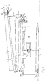
- Fig. 1 shows the side view of a treatment couch according to the invention, wherein some technical details of interest are shown when closed Housing would not be visible from the outside.
- 1 is a deck plate denotes, on which a mattress 2 is located and at the right end to a vertical Completing the deck 1 a headrest 3 is mounted.
- the deck plate 1 is mounted in a manner to be shown in more detail on a base 4, which rests on Verstellffure 5 on a floor 6.
- the base 4 In the base 4 is fixed to a linear drive with an electric motor 7 and one of this driven spindle lifting rod 8 attached.
- the spindle lifting rod 8 is on a console 9 mounted, via which the electric motor 7 and the spindle lifting rod. 8 can move a first intermediate plate 10.
- the first intermediate plate 10 is over on a rail 11 running linear guides 12 in Fig. 1 horizontal direction and thus displaceably mounted in the longitudinal direction of the deck plate 1. This direction thus corresponds to the Y direction.
- the first intermediate plate 10 carries about 17% -18% of the longitudinal extent on the side of the foot (drawing not to scale) a storage 13 with in Fig. 1 vertical Axis of rotation.
- a second intermediate plate 14 opposite the first intermediate plate 10 about the vertical axis through the bearing 13 rotatable held.
- the second intermediate plate 14 via a roller designated 15 supported on a running surface 16 of the first intermediate plate 10 and on the other hand connected to a driver 17, the one below in more detail described timing belt is driven.
- the toothed belt runs in a in Fig. 1 with 18 designated housing.
- the second intermediate plate 14 around the be pivoted by the bearing 13 running vertical axis which in the Y direction from the bearing 13 spaced areas, ie in particular in the area the headrest 3, an adjustment in a direction perpendicular to the plane of the drawing, namely the X-direction, corresponds.
- a pivot bearing 19 is provided on which the videplatte 1 is articulated.
- the deck plate 1 is articulated with a Spindle lifting rod 20 is connected, which is linearly driven by an electric motor 21 is in turn hinged to a mounting platform of the second intermediate plate 14th is appropriate.
- FIG. 2 shows the side view according to FIG. 1 with some deviations with respect to the adjustment positions.
- the comparison of FIGS. 1 and 2 shows, on the one hand, that by extension the spindle lifting rod 20 from the electric motor 21, the deck plate 1 to the Rotated pivot axis 19 and thus in the head area in the vertical direction, ie in the Z direction, can be raised.
- Figs. 1 and 2 shows that by moving the spindle lifting rod 8, here pulling in the electric motor 7, the first intermediate plate 10 and so that the second intermediate plate 14 and the deck plate 1 moves in the Y direction can be.
- Fig. 3 shows a plan view of the treatment table of FIGS. 1 and 2, wherein in particular, the mechanism for driving the driver 17 shown in more detail is.
- An electric motor 22 with lying in the Z direction of rotation drives a toothed belt 23, which is guided over four pulleys 24 and attached to the driver 17 is.
- a rotation of the output shaft of the electric motor 22 thus moves the Carrier 17 in the X direction and thus moves the second intermediate plate 14 relative to the first intermediate plate 10 in the X direction.
- This movement is illustrated in FIG. 4, wherein in solid lines with the head end according to FIG. 4 down adjustment in the X direction and in dashed lines in opposite set direction took place X-adjustment is located.
- the clarity the reference numbers are omitted in FIG. 4.
- the figures also show that the headrest 3 via two levers 25 hinged to the Couch plate 1 is attached.
- Fig. 1 and Fig. 2 further show that in the Z direction below the levers 25, a further Spindelhubstange 26 provided with an electric motor 27 is.
- the electric motor 27 is hinged to the headrest 3.
- the spindle lifting rod 26 is hinged to the deck plate 1.
- the comparison 1 and 2 shows that by retraction and extension of the screw jack 26 in and from the motor 27, a tilting movement of the headrest 3 about the hinge axis of the lever 25 takes place on the deck plate 1, with the particular automatic Tilt compensation for Z-adjustment of the deck plate 1 can accomplish.
- This tilt compensation is clearly visible in FIG.
- headrest 3 can also be tilted in other ways, if desired is.
- the automatic tilt compensation is done by appropriate tuning the control of the motor 27 to the drive of the motor 21st
- Fig. 5 shows the headrest of the treatment table in detail, in Sectional view seen in the X direction.
- the headrest 3 has a holding plate 28, the detailed structure of the following Figures becomes even clearer and the fastening screws 29 on the Treatment couch itself can be attached.
- the holding plate 28 is already in the Fig. 1 - 4 shown symbolically, but not numbered.
- the fastening screws engage in a metal plate 30 with corresponding threads, to relieve the otherwise made of plastic retaining plate 28. She also hold in the holding plate 28 a hinge box 31, in which already based Fig. 1 - 4 mentioned and shown there rack 26 is articulated.
- This head shell 32 consists of an anatomically shaped upper part 33 and an attached below Housing part 34, in which the already mentioned rack 26 protrudes.
- the housing part 34 is arranged below the plane of the electric motor 27, which is already shown in Fig. 1, with a clearly visible in Fig. 5 output pinion built-in.
- a guide 35 is provided which holds the rack 26 and leads, but in which this is displaceable. The guide 35 can be about the axis of the Output pinion of the electric motor 27 are pivoted and thus in the movement the headrest 3 a pivoting movement of the rack 26 about the articulated Attachment in the hinge box 31 follow.
- the headrest 33 consists essentially of a soft foam pad 36, via a hook and loop fastener 37 on an upper plate of the housing part 34th is appropriate. To facilitate insertion of this pad 36 may additionally Not shown here centering pins may be provided.
- This plate is, as Fig. 5 shows in the horizontal position of the head rest 33 something spaced from the holding plate 28, so protrudes in the holding plate 28 facing Direction not far beyond the remaining housing part 34 addition. Therefore arises at this point a slot between the housing part 34 and the holding plate 28, the is surmounted by the pad 36. There is no risk of jamming because of this Slot is sized so large that operators do not pinch their fingers easily can. Furthermore, the pad 36, which is in a downward movement quite closer to the support plate 28 can draw as drawn in Fig. 5, according to dodge above. This follows on the one hand from a certain deformability and is on the other hand, an advantage of the Velcro fastener 37.
- Fig. 6 shows an alternative embodiment to Fig. 5, in the same way at a Treatment couch according to FIGS. 1 - 4 may be attached. The following will be only the differences compared to FIG. 5 received.
- a centering pin 38 is shown, the pad 36 on the upper plate of the housing part 34 of the headrest 32 holds.
- the electric motor 27 is here replaced by a hand crank drive 39 with a worm gear 40, 41.
- the gear 41 of the worm gear is located on a common axis a pinion corresponding to the output gear 27 of FIG. 5 for driving the Rack 26.
- the hand crank 39 has a fold-out pin to facilitate cranking on, which is designated 42. It can be seen that the manual drive in the same way Part of the headrest 3, as for the electric motor 27 with the associated Drive parts in Fig. 5 applies. Incidentally, there are no fundamental differences to Fig. 5.
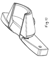
- FIG. 7 illustrates the headrest 3 of FIG. 6 in an exploded view.
- the pad 36 has a somewhat semicircular shape and the housing part 34th the headrest 32 is adapted to this semicircular shape and the pad 36 of keeps outside. It also recognizes the over the housing part 34 protruding part of the Pad 36 and an associated semicircular recess in the holding plate 28, in the this supernatant protrudes.
- FIG. 7 shows two more Joint boxes, which are designated 43 and are held by screws 44. These joint boxes 43 carry hinge pins, which on the housing part 34 of the headrest 32 are mounted on the other hand in the recognizable receiving holes of Retaining plate 28 is inserted and screwed with the screws 44.
- the fixing screws Incidentally, 29 and 44 also serve for fastening the retaining plate 28 on the other treatment couch in a manner not shown. she are through a plate of the treatment couch through by the holding plate 28 with the joint boxes 31 and 43 screwed.
- Fig. 7 shows in perspective the guide 35 for the rack 26 and the Worm gear 40, 41 of FIG. 6.
- the rack 26 is designed as a hollow tube. In not shown manner can be laid in the rack 26 so that electrical lines be, for example, if instead of the manual drive 39 - 42 an electric motor drive 27th is used.
- Fig. 8 shows an analogous representation to Fig. 7, but to the embodiment from Fig. 5. Further, in the illustration of Fig. 8 for illustration, the pad 36 omitted, the Fig. 7 shows. Incidentally, the explanations to the figures 5-7 referenced.
- FIGS. 9 and 10 show a side view of the headrest 3 from FIGS. 6 and 7 with a lower and an upper adjustment position and a perspective view the headrest 3 for a better understanding of Fig. 7.
- FIGS. 9 and 10 show a side view of the headrest 3 from FIGS. 6 and 7 with a lower and an upper adjustment position and a perspective view the headrest 3 for a better understanding of Fig. 7.
- Fig. 9 can be seen esp., That an adjustment with the manual drive 39 - 42 to leads that the headrest 32 relative to the support plate 28 moves upward and it is supported on the rack 26 and the hinge box 31.
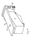
- Fig. 11 shows a schematic plan view of a further embodiment of the Clarification of the optional feature of an X-adjustment of the headrest 3.
- An the deck plate 1 with the Z-parallel axis of rotation 13 for the X-adjustment is the already mentioned holding plate 28 in this case via a motor-driven Rack 46 with motor 45 on an outer side (seen in the X direction) and attached via a hinge 47 on the opposite outer side.
- a motor-driven Rack 46 with motor 45 on an outer side (seen in the X direction) and attached via a hinge 47 on the opposite outer side.
- Fig. 12 shows another optional embodiment in which the X-adjustable Part of the treatment couch via an adjustable support leg 48 on the Ground is caught.
- This support leg 48 is shown here only symbolically and may be driven in practice to move during adjustment movements of the Lift off the ground and set up after adjustment for stabilization.
- the lower end of the support leg 48 can also roll with a rolling on the ground Be provided roll or a sliding surface.
- the support leg 48 is on a front side Plate attached, in turn, with the already mentioned intermediate plate 14th is connected, which in turn pivots about the axis 13 relative to the base 4 can be.
- the illustrated treatment couch is an integral part of one not in further Details shown and known per se laser surgery device for treatment of ametropia in the human eye.
- the headrest 3 Above the headrest 3 is the head attached to this device and directs a running in the Z direction laser beam in the eye, which brought with the treatment couch in the appropriate position must become.
- X-adjustment can between the two eyes of the patient be switched back and forth.
- the optical adjustment options of the laser device so that only the fine movements of the laser beam at the actual must Cover treatment.
- the positioning of the patient is independent of this over the treatment couch.
- the X-adjustment can also do so be used to facilitate the patient's entry.
Landscapes
- Health & Medical Sciences (AREA)
- Public Health (AREA)
- Biomedical Technology (AREA)
- Life Sciences & Earth Sciences (AREA)
- Animal Behavior & Ethology (AREA)
- General Health & Medical Sciences (AREA)
- Engineering & Computer Science (AREA)
- Veterinary Medicine (AREA)
- Accommodation For Nursing Or Treatment Tables (AREA)
- Finish Polishing, Edge Sharpening, And Grinding By Specific Grinding Devices (AREA)
- Mechanical Treatment Of Semiconductor (AREA)
- Inorganic Insulating Materials (AREA)
- Apparatus For Radiation Diagnosis (AREA)
- Radiation-Therapy Devices (AREA)
Priority Applications (12)
| Application Number | Priority Date | Filing Date | Title |
|---|---|---|---|
| DE20311153U DE20311153U1 (de) | 2003-07-18 | 2003-07-18 | Behandlungsliege mit Kopfstütze |
| DE20311152U DE20311152U1 (de) | 2003-07-18 | 2003-07-18 | Behandlungsliege |
| EP03016295A EP1498096A1 (de) | 2003-07-18 | 2003-07-18 | Behandlungsliege mit Kopfstütze |
| EP03016296A EP1498095B1 (de) | 2003-07-18 | 2003-07-18 | Behandlungsliege |
| AT03016296T ATE333859T1 (de) | 2003-07-18 | 2003-07-18 | Behandlungsliege |
| DE50304366T DE50304366D1 (de) | 2003-07-18 | 2003-07-18 | Behandlungsliege |
| ES03016296T ES2269876T3 (es) | 2003-07-18 | 2003-07-18 | Mesa de tratamiento. |
| PCT/EP2004/051525 WO2005009317A1 (de) | 2003-07-18 | 2004-07-16 | Behandlungsliege |
| CNA2004800266917A CN1852694A (zh) | 2003-07-18 | 2004-07-16 | 治疗床 |
| US10/565,093 US20060248648A1 (en) | 2003-07-18 | 2004-07-16 | Treatment couch |
| JP2006520829A JP2006528013A (ja) | 2003-07-18 | 2004-07-16 | 治療用バース |
| KR1020067001219A KR20060057575A (ko) | 2003-07-18 | 2004-07-16 | 치료 침대 |
Applications Claiming Priority (4)
| Application Number | Priority Date | Filing Date | Title |
|---|---|---|---|
| DE20311153U DE20311153U1 (de) | 2003-07-18 | 2003-07-18 | Behandlungsliege mit Kopfstütze |
| DE20311152U DE20311152U1 (de) | 2003-07-18 | 2003-07-18 | Behandlungsliege |
| EP03016295A EP1498096A1 (de) | 2003-07-18 | 2003-07-18 | Behandlungsliege mit Kopfstütze |
| EP03016296A EP1498095B1 (de) | 2003-07-18 | 2003-07-18 | Behandlungsliege |
Publications (1)
| Publication Number | Publication Date |
|---|---|
| EP1498096A1 true EP1498096A1 (de) | 2005-01-19 |
Family
ID=39800494
Family Applications (2)
| Application Number | Title | Priority Date | Filing Date |
|---|---|---|---|
| EP03016295A Withdrawn EP1498096A1 (de) | 2003-07-18 | 2003-07-18 | Behandlungsliege mit Kopfstütze |
| EP03016296A Expired - Lifetime EP1498095B1 (de) | 2003-07-18 | 2003-07-18 | Behandlungsliege |
Family Applications After (1)
| Application Number | Title | Priority Date | Filing Date |
|---|---|---|---|
| EP03016296A Expired - Lifetime EP1498095B1 (de) | 2003-07-18 | 2003-07-18 | Behandlungsliege |
Country Status (9)
| Country | Link |
|---|---|
| US (1) | US20060248648A1 (ko) |
| EP (2) | EP1498096A1 (ko) |
| JP (1) | JP2006528013A (ko) |
| KR (1) | KR20060057575A (ko) |
| CN (1) | CN1852694A (ko) |
| AT (1) | ATE333859T1 (ko) |
| DE (3) | DE20311153U1 (ko) |
| ES (1) | ES2269876T3 (ko) |
| WO (1) | WO2005009317A1 (ko) |
Cited By (2)
| Publication number | Priority date | Publication date | Assignee | Title |
|---|---|---|---|---|
| EP1702535A1 (de) * | 2005-03-17 | 2006-09-20 | Erich Kratzmaier | Behandlungsliege mit Kniestütze |
| US10869798B2 (en) * | 2006-05-05 | 2020-12-22 | Warsaw Orthopedic, Inc. | Patient positioning support apparatus with virtual pivot-shift pelvic pads, upper body stabilization and fail-safe table attachment mechanism |
Families Citing this family (13)
| Publication number | Priority date | Publication date | Assignee | Title |
|---|---|---|---|---|
| KR100823693B1 (ko) * | 2006-08-04 | 2008-04-18 | (주)이우테크놀로지 | 레이저 수술기가 구비된 치과용 유닛체어 |
| DE102006062884A1 (de) | 2006-10-27 | 2008-08-07 | KÖRBER, Ralf | Grundgestell |
| JP2013169289A (ja) * | 2012-02-20 | 2013-09-02 | Mitsubishi Heavy Ind Ltd | 患者傾動装置付きカウチ |
| EP2689761A1 (en) | 2012-07-26 | 2014-01-29 | Fundación para la Investigación del hospital Universitario y Politécnico de la Fe | Stretcher with a movable headrest, its use and a movable headrest assembly for stretchers or beds |
| US10045768B2 (en) * | 2014-07-06 | 2018-08-14 | Javier Garcia-Bengochea | Methods and devices for surgical access |
| CN104812445A (zh) * | 2014-09-22 | 2015-07-29 | 数码医疗集团 | 一种多角度运动治疗床 |
| US9457904B1 (en) * | 2016-01-07 | 2016-10-04 | Robert Karl Fey | Sleeping platform for use on aircraft |
| CN106901933A (zh) * | 2017-03-15 | 2017-06-30 | 北京唯迈医疗设备有限公司 | 医用床台及其控制方法 |
| CN107320127B (zh) * | 2017-06-28 | 2020-07-28 | 马莉 | 一种用于放射科具有摆动功能的人体承载设备 |
| CN107625596B (zh) * | 2017-09-27 | 2023-08-01 | 宝鸡大医数码机器人有限责任公司 | 一种医用六自由度治疗床 |
| CN108114379B (zh) * | 2017-12-21 | 2020-02-14 | 山东省肿瘤防治研究院 | 一种医用电子直线加速器摆位定位装置 |
| CN108969229A (zh) * | 2018-06-27 | 2018-12-11 | 东莞唯度电子科技服务有限公司 | 一种内科检测辅助器 |
| CN109875817A (zh) * | 2019-04-01 | 2019-06-14 | 王风晓 | 一种医用麻醉科介入治疗辅助装置 |
Citations (7)
| Publication number | Priority date | Publication date | Assignee | Title |
|---|---|---|---|---|
| US4353595A (en) * | 1979-12-27 | 1982-10-12 | Kabushiki Kaisha Morita Seisakusho | Headrest control device for a treatment chair |
| GB2133678A (en) * | 1983-01-05 | 1984-08-01 | Denyers Pty Ltd | Operating table |
| US4466425A (en) * | 1981-01-20 | 1984-08-21 | Carlo Maggi | Operating table for ophthalmic surgery |
| US4840429A (en) * | 1987-08-14 | 1989-06-20 | Siemens Aktiengesellschaft | Motor-adjustable head support for a dental treatment chair |
| DE29905089U1 (de) * | 1999-03-19 | 1999-08-05 | Grote Manfred | Behandlungsliege |
| WO2001072226A1 (en) * | 2000-03-29 | 2001-10-04 | Stille Surgical Ab | Surgical table with displacement arrangement |
| US20010041885A1 (en) * | 1996-05-30 | 2001-11-15 | Kristian Hohla | Excimer laser eye surgery system |
Family Cites Families (3)
| Publication number | Priority date | Publication date | Assignee | Title |
|---|---|---|---|---|
| US4660549A (en) * | 1985-09-12 | 1987-04-28 | Standex International | Adjustable head support for chiropractic table |
| US5013018A (en) * | 1989-06-22 | 1991-05-07 | Sicek Bernard W | Table positioning for X-ray examinations in plurality of positions |
| EP0923922A3 (en) * | 1997-12-18 | 2000-02-09 | Stille-Beta, Inc. | Improved operating room table |
-
2003
- 2003-07-18 AT AT03016296T patent/ATE333859T1/de not_active IP Right Cessation
- 2003-07-18 DE DE20311153U patent/DE20311153U1/de not_active Expired - Lifetime
- 2003-07-18 EP EP03016295A patent/EP1498096A1/de not_active Withdrawn
- 2003-07-18 DE DE20311152U patent/DE20311152U1/de not_active Expired - Lifetime
- 2003-07-18 EP EP03016296A patent/EP1498095B1/de not_active Expired - Lifetime
- 2003-07-18 DE DE50304366T patent/DE50304366D1/de not_active Expired - Fee Related
- 2003-07-18 ES ES03016296T patent/ES2269876T3/es not_active Expired - Lifetime
-
2004
- 2004-07-16 WO PCT/EP2004/051525 patent/WO2005009317A1/de active Application Filing
- 2004-07-16 CN CNA2004800266917A patent/CN1852694A/zh active Pending
- 2004-07-16 JP JP2006520829A patent/JP2006528013A/ja not_active Withdrawn
- 2004-07-16 US US10/565,093 patent/US20060248648A1/en not_active Abandoned
- 2004-07-16 KR KR1020067001219A patent/KR20060057575A/ko active IP Right Grant
Patent Citations (7)
| Publication number | Priority date | Publication date | Assignee | Title |
|---|---|---|---|---|
| US4353595A (en) * | 1979-12-27 | 1982-10-12 | Kabushiki Kaisha Morita Seisakusho | Headrest control device for a treatment chair |
| US4466425A (en) * | 1981-01-20 | 1984-08-21 | Carlo Maggi | Operating table for ophthalmic surgery |
| GB2133678A (en) * | 1983-01-05 | 1984-08-01 | Denyers Pty Ltd | Operating table |
| US4840429A (en) * | 1987-08-14 | 1989-06-20 | Siemens Aktiengesellschaft | Motor-adjustable head support for a dental treatment chair |
| US20010041885A1 (en) * | 1996-05-30 | 2001-11-15 | Kristian Hohla | Excimer laser eye surgery system |
| DE29905089U1 (de) * | 1999-03-19 | 1999-08-05 | Grote Manfred | Behandlungsliege |
| WO2001072226A1 (en) * | 2000-03-29 | 2001-10-04 | Stille Surgical Ab | Surgical table with displacement arrangement |
Cited By (3)
| Publication number | Priority date | Publication date | Assignee | Title |
|---|---|---|---|---|
| EP1702535A1 (de) * | 2005-03-17 | 2006-09-20 | Erich Kratzmaier | Behandlungsliege mit Kniestütze |
| WO2006097523A1 (de) * | 2005-03-17 | 2006-09-21 | Erich Kratzmaier | Behandlungsliege mit kniestütze |
| US10869798B2 (en) * | 2006-05-05 | 2020-12-22 | Warsaw Orthopedic, Inc. | Patient positioning support apparatus with virtual pivot-shift pelvic pads, upper body stabilization and fail-safe table attachment mechanism |
Also Published As
| Publication number | Publication date |
|---|---|
| JP2006528013A (ja) | 2006-12-14 |
| ATE333859T1 (de) | 2006-08-15 |
| CN1852694A (zh) | 2006-10-25 |
| ES2269876T3 (es) | 2007-04-01 |
| DE20311153U1 (de) | 2004-12-02 |
| WO2005009317A1 (de) | 2005-02-03 |
| DE50304366D1 (de) | 2006-09-07 |
| DE20311152U1 (de) | 2004-12-02 |
| KR20060057575A (ko) | 2006-05-26 |
| EP1498095B1 (de) | 2006-07-26 |
| US20060248648A1 (en) | 2006-11-09 |
| EP1498095A1 (de) | 2005-01-19 |
Similar Documents
| Publication | Publication Date | Title |
|---|---|---|
| EP1498095B1 (de) | Behandlungsliege | |
| EP2792277B1 (de) | Elektromotorischer möbelantrieb | |
| DE60118160T2 (de) | Bettseitenteil | |
| DE69738141T2 (de) | Patientenliege | |
| EP1708595B1 (de) | Möbelantrieb zum verstellen eines ersten teiles eines möbels relativ zu einem zweiten teil | |
| EP1294255B1 (de) | Möbelantrieb zum verstellen von teilen eines möbels relativ zueinander | |
| WO2004006725A1 (de) | Verstellvorrichtung sowie verstellbare unterstützungsvorrichtung für betten, matratzen, sessel und dergleichen | |
| DE60022252T2 (de) | Massagevorrichtung zum Einbau in der Rückenlehne eines Sessels, versehen mit Massagedruckregulierung | |
| DE102013110096A1 (de) | Aufstellhebelmechanik mit Bowdenzug | |
| DE3719012A1 (de) | Gestell zum halten einer arbeitsplatte | |
| DE102005023477A1 (de) | Vorrichtung zur Lagerung eines Patienten für eine minimalinvasive Implantation eines künstlichen Hüftgelenks | |
| EP1702535B1 (de) | Behandlungsliege mit Kniestütze | |
| DE602004001175T2 (de) | Kernspintomograph | |
| EP2086489B1 (de) | Zahnärztlicher behandlungsstuhl | |
| DE3727186C2 (ko) | ||
| DE4405619C1 (de) | Höhenverstellbare Bett/Nachtschrank-Kombination | |
| DE4230013A1 (de) | Bett, sowie verstellbare bettboden und matratze dafuer | |
| DE2640985C3 (de) | Vorrichtung zum Überführen eines Patienten aus einer liegenden in eine sitzende Stellung und umgekehrt | |
| RU2261695C2 (ru) | Кровать функциональная (варианты) | |
| EP0474055A1 (de) | Einrichtung zur insbesondere postoperativen Behandlung eines Schulter- und/oder Ellbogengelenkes | |
| DE2049282A1 (de) | Stuhl für Patienten | |
| EP0800810B1 (de) | Therapieliege | |
| EP0329951A2 (de) | Bett zur Lagerung immobiler Patienten | |
| DE102020131204A1 (de) | Elektromotorisch verstellbare Stützeinrichtung | |
| EP0838206A1 (de) | Bett mit höhen- und neigungsverstellbarer Liegefläche |
Legal Events
| Date | Code | Title | Description |
|---|---|---|---|
| PUAI | Public reference made under article 153(3) epc to a published international application that has entered the european phase |
Free format text: ORIGINAL CODE: 0009012 |
|
| AK | Designated contracting states |
Kind code of ref document: A1 Designated state(s): AT BE BG CH CY CZ DE DK EE ES FI FR GB GR HU IE IT LI LU MC NL PT RO SE SI SK TR |
|
| AX | Request for extension of the european patent |
Extension state: AL LT LV MK |
|
| 17P | Request for examination filed |
Effective date: 20050712 |
|
| AKX | Designation fees paid |
Designated state(s): AT BE BG CH CY CZ DE DK EE ES FI FR GB GR HU IE IT LI LU MC NL PT RO SE SI SK TR |
|
| 17Q | First examination report despatched |
Effective date: 20051006 |
|
| STAA | Information on the status of an ep patent application or granted ep patent |
Free format text: STATUS: THE APPLICATION IS DEEMED TO BE WITHDRAWN |
|
| 18D | Application deemed to be withdrawn |
Effective date: 20090203 |