EP1497804B1 - Remote control with low battery indication and corresponding method - Google Patents
Remote control with low battery indication and corresponding method Download PDFInfo
- Publication number
- EP1497804B1 EP1497804B1 EP03719806A EP03719806A EP1497804B1 EP 1497804 B1 EP1497804 B1 EP 1497804B1 EP 03719806 A EP03719806 A EP 03719806A EP 03719806 A EP03719806 A EP 03719806A EP 1497804 B1 EP1497804 B1 EP 1497804B1
- Authority
- EP
- European Patent Office
- Prior art keywords
- remote control
- voltage
- control apparatus
- key
- backlight
- Prior art date
- Legal status (The legal status is an assumption and is not a legal conclusion. Google has not performed a legal analysis and makes no representation as to the accuracy of the status listed.)
- Expired - Lifetime
Links
- 238000000034 method Methods 0.000 title claims description 27
- 230000007246 mechanism Effects 0.000 claims description 10
- 230000004913 activation Effects 0.000 claims 3
- 230000005540 biological transmission Effects 0.000 claims 1
- 230000006870 function Effects 0.000 description 8
- 230000008569 process Effects 0.000 description 5
- 230000003213 activating effect Effects 0.000 description 3
- 230000001010 compromised effect Effects 0.000 description 3
- 238000010586 diagram Methods 0.000 description 2
- 238000005286 illumination Methods 0.000 description 2
- 230000007423 decrease Effects 0.000 description 1
- 230000003247 decreasing effect Effects 0.000 description 1
- 230000007812 deficiency Effects 0.000 description 1
- 230000001419 dependent effect Effects 0.000 description 1
- 238000011156 evaluation Methods 0.000 description 1
- 239000004973 liquid crystal related substance Substances 0.000 description 1
- 230000010399 physical interaction Effects 0.000 description 1
- 230000004044 response Effects 0.000 description 1
Images

Classifications
-
- G—PHYSICS
- G08—SIGNALLING
- G08C—TRANSMISSION SYSTEMS FOR MEASURED VALUES, CONTROL OR SIMILAR SIGNALS
- G08C17/00—Arrangements for transmitting signals characterised by the use of a wireless electrical link
- G08C17/02—Arrangements for transmitting signals characterised by the use of a wireless electrical link using a radio link
-
- G—PHYSICS
- G08—SIGNALLING
- G08C—TRANSMISSION SYSTEMS FOR MEASURED VALUES, CONTROL OR SIMILAR SIGNALS
- G08C23/00—Non-electrical signal transmission systems, e.g. optical systems
- G08C23/04—Non-electrical signal transmission systems, e.g. optical systems using light waves, e.g. infrared
-
- G—PHYSICS
- G01—MEASURING; TESTING
- G01R—MEASURING ELECTRIC VARIABLES; MEASURING MAGNETIC VARIABLES
- G01R19/00—Arrangements for measuring currents or voltages or for indicating presence or sign thereof
- G01R19/165—Indicating that current or voltage is either above or below a predetermined value or within or outside a predetermined range of values
- G01R19/16533—Indicating that current or voltage is either above or below a predetermined value or within or outside a predetermined range of values characterised by the application
- G01R19/16538—Indicating that current or voltage is either above or below a predetermined value or within or outside a predetermined range of values characterised by the application in AC or DC supplies
- G01R19/16542—Indicating that current or voltage is either above or below a predetermined value or within or outside a predetermined range of values characterised by the application in AC or DC supplies for batteries
-
- G—PHYSICS
- G01—MEASURING; TESTING
- G01R—MEASURING ELECTRIC VARIABLES; MEASURING MAGNETIC VARIABLES
- G01R31/00—Arrangements for testing electric properties; Arrangements for locating electric faults; Arrangements for electrical testing characterised by what is being tested not provided for elsewhere
- G01R31/36—Arrangements for testing, measuring or monitoring the electrical condition of accumulators or electric batteries, e.g. capacity or state of charge [SoC]
- G01R31/3644—Constructional arrangements
- G01R31/3648—Constructional arrangements comprising digital calculation means, e.g. for performing an algorithm
Definitions
- This invention relates generally to the field of remote controls for controlling electronic devices, and specifically to apparatus and methods for indicating when the batteries/power source for such remote controls is low.
- Remote control devices are used to control electronic devices such as televisions, video cassette recorders, digital versatile disc players, stereos, digital recorders, cable boxes, etc. Most remote controls are wireless and have an internal energy source such as a battery to provide the necessary power to the remote control device. Wireless capability allows a user to control the desired electronic device from almost anywhere in a room and without having to be in physical contact with the device. As the capabilities, functionality, and complexity of electronic devices have increased over the years, so has the dependency of the user an the remote control.
- a single remote control can be used to control a plurality of electronic devices.
- the increased capabilities and applications of remote controls have resulted in an increased use of the internal power source, e.g., batteries, of the remote control.
- the voltage of the batteries may be decreased to a point where the remote control either operates poorly and/or stops working completely. This is undesirably not only because the user loses the ability to control electronic devices without physical interaction, but also because the user's programming that is saved within a volatile memory of the remote control, for example, programming multiple universal devices and learned codes, will be lost.
- the batteries are replaced before the voltage level of the batteries get too low, these problems can be avoided.
- the electronic device does not have a display screen or is not capable of deciphering the hexcode, the message will not be displayed to the user.
- this coordination between remote control and electronic device cannot be implemented if the remote control is sold as a replacement for an original remote control of a different brand and/or having different compatibility requirements.
- LED light emitting diode
- Specially dedicated LED's are located an the remote control itself and do not require cooperation with the electronic device in order to alert the user of a low voltage status of the battery.
- specially dedicated LED's increase the cost of the remote, take up additional space an the remote control face, and use additional voltage from the batteries.
- some remote controls have replaced the specially dedicated LED with a liquid crystal display (“LCD”) for displaying a low battery icon.
- LCD liquid crystal display
- JP-A-11154878 discloses a wireless remote controller powered by a built-in battery, The wireless remote control indicates three different voltage levels of the built-in battery by lighting up one or more of the three areas on the keyboard of the wireless remote control. However, three additional switches are required to provide such indications.
- Another object of the present invention is to provide a method and remote control apparatus that can alert a user of a low voltage state without the need for cooperation with an electronic device.
- Yet another object of the present invention is to provide a method and remote control apparatus that can alert a user of a low voltage state without using a specially designated indicator, such as an LED or an LCD icon.
- Still another object of the of the present invention is to provide a method and remote control apparatus that can alert a user of a low voltage state while conserving the remaining voltage of the power source.
- a yet further object is to provide a more cost effective method and remote control apparatus that can alert a user of a low voltage state.
- activating the backlight source in the first way comprises illuminating the backlight source for a first predetermined time and activating the backlight source in the second way comprises illuminating the backlight source for a second predetermined time.
- activating the backlight source in the second way can comprise flashing the backlight source for a third predetermined time.
- the predefined threshold can be at or about approximately 0.2 volts and the user input mechanism can be a backlight key, channel key, a volume key, a number key, a power key, or a mute key.
- the indicator can comprise a plurality of backlight LED's.
- the power source can be a battery.
- the invention is a method for indicating when a power source of a remote control apparatus is in a low voltage state as defined in claim 14.
- the inventive method preferably comprises the further step of transmitting a signal to an electronic device indicating that the voltage is at or below the predefined threshold.
- the remote control apparatus used to carry out the inventive method preferably comprises the hardware and functions, as described above in relation to the remote control apparatus of the present invention.
- FIG. 1 is a schematic of a remote control apparatus according to the present invention.
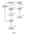
- FIG. 2 is flowchart diagram of a method for indicating when a power source of a remote control apparatus is in a low voltage state according to the present invention.
- the first way It is not uncommon for current remote controls to have a backlight which, when activated, illuminates the user keys of the remote control for a predetermined period of time, typically about 6 seconds, referred to herein as "the first way."
- the backlight is activated by a user pressing either any key or a dedicated backlight key on the remote control.
- the backlight illumination allows the user to more easily operate the remote control in poor lighting conditions.
- the backlight key when a user presses the backlight key when the batteries are in a low voltage state (defined by a threshold voltage), instead of the backlight being illuminated for 6 seconds, the backlight will only be illuminated for 1 second, "the second way.”
- the user can easily recognize when the batteries need to be changed before the operability of the remote control is compromised and/or lost when the backlighting illuminates the second way upon pressing any remote key.
- remote control 100 an exemplary embodiment of the present invention is schematically illustrated.
- Remote control 100 comprises a plurality of user input keys, namely channel up key 110, channel down key 120, volume up key 130, volume down key 140, and backlight key 150. These five user input keys are illustrated for exemplary purpose only, those skilled in the art will appreciate that remote control 100 can comprise numerous other user input keys such as a power key, a mute key, or a plurality of number keys.
- CPU 160 When a user presses one of the user input keys 110-150 , CPU 160 receives a corresponding signal via bus 400.
- CPU 160 is programmed so that upon receipt of a signal from user input keys 110-150, it will carry out the desired function.
- Remote control 100 further comprises CPU 160, backlight 170, infrared (“IR”) transmitter 180, voltage meter 190, and battery 199.
- Remotes having other types of transmitters, for example radio frequency (“RF"), can be used.
- Battery 199 can be any conventional single battery or a plurality of batteries in combination. Battery 199 acts as a power source for CPU 160 and provides the energy necessary for remote control 100 to function via connection 320. Battery 199 has a voltage that starts at a certain level and gradually decreases as it is used.
- Voltage meter 190 is operably coupled to battery 199 and CPU 160. Through programming, voltage meter 190 is adapted to monitor and/or measure the voltage level of battery 199 and communicate this voltage level to CPU 160 for evaluation.
- CPU 160 is also operably coupled to backlight 170 and IR transmitter 180.
- CPU 160 can activate/deactivate backlight 170.
- backlight 170 is positioned behind transparent or translucent user input keys of remote control 100.
- Backlight 170 can be a backlight LED or a plurality of backlight LED's. Other types of backlighting can be used, for example electroluminescent panels. When activated, backlight 170 is illuminated, causing the user input keys to appear to be illuminated.
- CPU 160 can also activate/use IR transmitter 180 to send signals to an electronic device.
- IR transmitter 180 is adapted to send control signals corresponding to user inputs to an IR sensor on the electronic device (not illustrated).
- FIG. 2 is a flowchart diagram of an embodiment of a method for indicating when battery 199 of remote control 100 is in a low voltage state according to the present invention. The inventive method of FIG. 2 will be discussed in relation to the hardware of FIG. 1.
- voltage meter 190 monitors and/or measures the voltage of battery 199 via connection 390.
- voltage meter 190 can be adapted to measure the output voltage of battery 199 along connection 320 rather than the voltage of the battery itself.
- Voltage meter 190 can also be positioned in series between battery 199 and CPU 160.
- CPU 160 can be programmed so that the voltage measuring function of voltage meter 190 is initiated upon a user entering a command by pressing one of user input keys 110-150.
- CPU 160 can be programmed to initiate the voltage measuring function of voltage meter 190 at set intervals of time or continuously.
- voltage meter 190 communicates the voltage reading to CPU 160 via connection 360.
- CPU 160 is programmed to analyze the incoming voltage reading data and compare it to a predefined threshold voltage.
- battery 199 can provide enough electrical energy to remote control 100 so that operability is not compromised.
- the predefined threshold can be 0.2 volts.
- decision block 210 is executed by CPU 160.
- CPU 160 compares the voltage reading data received from voltage meter 190 to the predefined threshold voltage stored in CPU 160, in this case 0.2 volts. If the voltage reading data indicates that the voltage of battery 199 is at or above 0.2 volts, the answer to decision block 210 is NO and CPU 160 proceeds to decision block 220.
- CPU 160 analyzes the user input signal received from bus 400 via connection 350 to determine what key 110-150 was activated by the user. If backlight key 150 was activated, the answer to decision block 220 is YES and CPU 160 send a signal to backlight 170 via connection 350, causing backlight 170 to illuminate for a normal duration, e.g., six seconds. However, if backlight key 150 was not pressed, i.e., a different key was pressed, the answer to decision block 220 is NO. CPU 160 will then proceed to process block 270 and carry out the user requested function.
- CPU 160 is programmed to then proceed to process block 230 and set a low-voltage flag in the software. Once the low voltage flag is set, CPU 160 proceeds to decision block 240.
- CPU 160 analyzes the user input signal received from bus 400 via connection 350 to determine what key 110-150 was activated by the user. If backlight key 150 was activated, the answer to decision block 240 is YES and CPU 160 send a signal to backlight 170 via connection 350, causing backlight 170 to illuminate for a shortened duration, e.g., one second. This one-second flash of backlight 170 is an indication to the user that battery 190 needs to be replaced in remote control 100. The shortened duration of illumination of backlight 170 also acts to conserve the energy of battery 190 by reducing the draining of battery 190.
- backlight 170 can be a plurality of LED's positioned on remote control 100.
- CPU 160 can be programmed to only light up one of the LED's when the battery level is low instead of all of the LED's as normal.
- CPU 160 can be programmed to light up the LED's in a sequence when the battery level is low instead of all of the LED's being illuminated simultaneously as normal.
- the backlight illuminates in the first way whenever any key is pressed and the voltage is above the predetermined threshold, and in the second way when any key is pressed when the voltage is below the predetermined threshold.
- Remote control 100 can also be adapted to also have the ability to send out the a Low Voltage Display (“LVD”) IR hexcode signal via IR transmitter 180 to the electronic device in addition to the backlighting features described above, which causes a pop up message or icon in the on-screen display (“OSD”) to signify that the remote battery voltage is low. This can be accomplished by properly programming CPU 160.
- the backlight can also be used as a feedback indication when programming the remote rather than having a dedicated LED for programming mode feedback.
Landscapes
- Physics & Mathematics (AREA)
- General Physics & Mathematics (AREA)
- Engineering & Computer Science (AREA)
- Computer Networks & Wireless Communication (AREA)
- Selective Calling Equipment (AREA)
- Details Of Television Systems (AREA)
- Circuit Arrangement For Electric Light Sources In General (AREA)
Applications Claiming Priority (3)
| Application Number | Priority Date | Filing Date | Title |
|---|---|---|---|
| US37453502P | 2002-04-22 | 2002-04-22 | |
| US374535P | 2002-04-22 | ||
| PCT/US2003/011874 WO2003090178A1 (en) | 2002-04-22 | 2003-04-17 | Remote control with low battery indication |
Publications (2)
| Publication Number | Publication Date |
|---|---|
| EP1497804A1 EP1497804A1 (en) | 2005-01-19 |
| EP1497804B1 true EP1497804B1 (en) | 2006-06-21 |
Family
ID=29251203
Family Applications (1)
| Application Number | Title | Priority Date | Filing Date |
|---|---|---|---|
| EP03719806A Expired - Lifetime EP1497804B1 (en) | 2002-04-22 | 2003-04-17 | Remote control with low battery indication and corresponding method |
Country Status (10)
| Country | Link |
|---|---|
| US (1) | US7411515B2 (enExample) |
| EP (1) | EP1497804B1 (enExample) |
| JP (1) | JP2005523623A (enExample) |
| KR (1) | KR100987209B1 (enExample) |
| CN (1) | CN100414965C (enExample) |
| AU (1) | AU2003223665A1 (enExample) |
| DE (1) | DE60306354T2 (enExample) |
| MX (1) | MXPA04010328A (enExample) |
| MY (1) | MY138561A (enExample) |
| WO (1) | WO2003090178A1 (enExample) |
Families Citing this family (22)
| Publication number | Priority date | Publication date | Assignee | Title |
|---|---|---|---|---|
| JP2007166401A (ja) * | 2005-12-15 | 2007-06-28 | Toshiba Corp | リモコン装置 |
| KR101349798B1 (ko) * | 2006-10-27 | 2014-01-10 | 엘지전자 주식회사 | 동작제어방법 및 이를 구현할 수 있는 전자기기 |
| US8082455B2 (en) * | 2008-03-27 | 2011-12-20 | Echostar Technologies L.L.C. | Systems and methods for controlling the power state of remote control electronics |
| US9520743B2 (en) * | 2008-03-27 | 2016-12-13 | Echostar Technologies L.L.C. | Reduction of power consumption in remote control electronics |
| US8009054B2 (en) * | 2008-04-16 | 2011-08-30 | Echostar Technologies L.L.C. | Systems, methods and apparatus for adjusting a low battery detection threshold of a remote control |
| US7907060B2 (en) * | 2008-05-08 | 2011-03-15 | Echostar Technologies L.L.C. | Systems, methods and apparatus for detecting replacement of a battery in a remote control |
| US20090303097A1 (en) * | 2008-06-09 | 2009-12-10 | Echostar Technologies Llc | Systems, methods and apparatus for changing an operational mode of a remote control |
| US8305249B2 (en) | 2008-07-18 | 2012-11-06 | EchoStar Technologies, L.L.C. | Systems and methods for controlling power consumption in electronic devices |
| US8134475B2 (en) * | 2009-03-16 | 2012-03-13 | Echostar Technologies L.L.C. | Backlighting remote controls |
| KR101603340B1 (ko) * | 2009-07-24 | 2016-03-14 | 엘지전자 주식회사 | 제어 장치 및 그 동작 방법 |
| US20110074590A1 (en) * | 2009-09-28 | 2011-03-31 | Eric Sacknoff | Smoke detector with wireless muting system |
| US8525520B2 (en) * | 2010-05-26 | 2013-09-03 | Landis+Gyr Innovations, Inc. | System and method for low battery detection |
| US20120280544A1 (en) * | 2011-05-06 | 2012-11-08 | Earl Jansen Wiley | Universal remote control chair |
| US20130188960A1 (en) * | 2011-07-25 | 2013-07-25 | Xiuzhi Gao | One-Handed Remote Unit That Can Control Multiple Devices |
| CN103576092A (zh) * | 2012-07-20 | 2014-02-12 | 珠海格力电器股份有限公司 | 遥控器及其电池电量的检测装置和检测方法 |
| US8847775B2 (en) * | 2012-11-30 | 2014-09-30 | Panasonic Corporation | Tangible charge level awareness method and apparatus using augmented batteries |
| CN109547826A (zh) * | 2018-12-03 | 2019-03-29 | 四川长虹电器股份有限公司 | 基于智能电视的遥控器低电量提示方法 |
| CN110572918B (zh) * | 2019-09-17 | 2021-11-23 | Tcl空调器(中山)有限公司 | 遥控器背光调节方法及其装置以及存储介质 |
| CN111145520A (zh) * | 2019-12-27 | 2020-05-12 | 深圳市创荣发电子有限公司 | 遥控器和控制方法 |
| FR3110016B1 (fr) * | 2020-05-07 | 2022-04-08 | Cogelec | Clef électronique pour déverrouiller une serrure électronique |
| CN111816128B (zh) * | 2020-07-22 | 2022-03-11 | Tcl空调器(中山)有限公司 | 遥控器及其控制方法、控制装置、存储介质 |
| CN117177417A (zh) * | 2023-09-05 | 2023-12-05 | 安徽华宇电子科技有限公司 | 一种遥控器低电量控制系统及方法 |
Family Cites Families (24)
| Publication number | Priority date | Publication date | Assignee | Title |
|---|---|---|---|---|
| DE2805896A1 (de) * | 1978-02-13 | 1979-08-16 | Hoermann Kg Antrieb Steuertec | Handsender fuer zwei unterschiedliche signale |
| US4649373A (en) * | 1983-08-10 | 1987-03-10 | International Business Machines Corporation | Powered conservation system in battery powered keyboard device including a microprocessor |
| US4578671A (en) * | 1984-12-05 | 1986-03-25 | International Business Machines Corp. | Remote indicating low battery voltage enunciator method and apparatus |
| US4959810A (en) * | 1987-10-14 | 1990-09-25 | Universal Electronics, Inc. | Universal remote control device |
| JPH0272326A (ja) * | 1988-09-07 | 1990-03-12 | Canon Inc | 電子機器 |
| US4890108A (en) * | 1988-09-09 | 1989-12-26 | Clifford Electronics, Inc. | Multi-channel remote control transmitter |
| JPH0573182A (ja) * | 1991-09-11 | 1993-03-26 | Canon Inc | 情報処理装置 |
| US5506572A (en) * | 1993-06-23 | 1996-04-09 | Lodgenet Entertainment Corporation | Low battery detection system |
| US5543776A (en) * | 1993-10-19 | 1996-08-06 | Whistler Corporation | Vehicle security system |
| KR950016433A (ko) * | 1993-11-30 | 1995-06-17 | 김광호 | 리모콘의 로우 밧데리 표시방법 |
| US5686887A (en) * | 1994-12-07 | 1997-11-11 | Schoeferisch Aeusserung Anstalt | Electronic locating device |
| US5684471A (en) * | 1995-07-24 | 1997-11-04 | Zenith Electronics Corporation | IR remote control transmitter with power saving feature |
| JPH11110660A (ja) * | 1997-10-08 | 1999-04-23 | Matsushita Electric Ind Co Ltd | 遠隔制御装置 |
| JP3319579B2 (ja) * | 1997-10-17 | 2002-09-03 | 河西工業株式会社 | エスカッションの取付構造 |
| JPH11154878A (ja) * | 1997-11-20 | 1999-06-08 | Funai Electric Co Ltd | 無線遠隔制御装置 |
| JPH11176286A (ja) * | 1997-12-15 | 1999-07-02 | Canon Inc | リモートコントロール装置 |
| US6098175A (en) * | 1998-02-24 | 2000-08-01 | Smartpower Corporation | Energy-conserving power-supply system |
| US6353800B1 (en) * | 1999-08-06 | 2002-03-05 | Spotware Technologies, Inc. | Method, system, signal and software for sensing remote battery life based upon cursor characteristics |
| JP2002032980A (ja) * | 2000-07-18 | 2002-01-31 | Aiwa Co Ltd | 電池残量表示装置 |
| JP2002077378A (ja) * | 2000-08-31 | 2002-03-15 | Kyocera Corp | 携帯電話機 |
| EP1611834B1 (en) * | 2000-12-21 | 2011-03-16 | Insulet Corporation | Medical apparatus remote control and method |
| US6794992B1 (en) * | 2000-12-29 | 2004-09-21 | Bellsouth Intellectual Property Corporation | Integrated remote control unit for operating a television and a video game unit |
| US20030012563A1 (en) * | 2001-07-10 | 2003-01-16 | Darrell Neugebauer | Space heater with remote control |
| US7746242B2 (en) * | 2004-07-21 | 2010-06-29 | Honeywell International Inc. | Low battery indicator |
-
2003
- 2003-04-17 DE DE60306354T patent/DE60306354T2/de not_active Expired - Lifetime
- 2003-04-17 JP JP2003586847A patent/JP2005523623A/ja active Pending
- 2003-04-17 CN CNB038086956A patent/CN100414965C/zh not_active Expired - Lifetime
- 2003-04-17 WO PCT/US2003/011874 patent/WO2003090178A1/en not_active Ceased
- 2003-04-17 US US10/512,317 patent/US7411515B2/en not_active Expired - Lifetime
- 2003-04-17 MX MXPA04010328A patent/MXPA04010328A/es active IP Right Grant
- 2003-04-17 KR KR1020047016936A patent/KR100987209B1/ko not_active Expired - Lifetime
- 2003-04-17 EP EP03719806A patent/EP1497804B1/en not_active Expired - Lifetime
- 2003-04-17 AU AU2003223665A patent/AU2003223665A1/en not_active Abandoned
- 2003-04-21 MY MYPI20031492A patent/MY138561A/en unknown
Also Published As
| Publication number | Publication date |
|---|---|
| CN100414965C (zh) | 2008-08-27 |
| MXPA04010328A (es) | 2005-02-03 |
| WO2003090178A1 (en) | 2003-10-30 |
| KR100987209B1 (ko) | 2010-10-12 |
| KR20040106362A (ko) | 2004-12-17 |
| DE60306354D1 (de) | 2006-08-03 |
| DE60306354T2 (de) | 2007-06-14 |
| US20050146438A1 (en) | 2005-07-07 |
| AU2003223665A1 (en) | 2003-11-03 |
| CN1647126A (zh) | 2005-07-27 |
| MY138561A (en) | 2009-06-30 |
| US7411515B2 (en) | 2008-08-12 |
| JP2005523623A (ja) | 2005-08-04 |
| EP1497804A1 (en) | 2005-01-19 |
Similar Documents
| Publication | Publication Date | Title |
|---|---|---|
| EP1497804B1 (en) | Remote control with low battery indication and corresponding method | |
| US7786623B2 (en) | Power management for electronic devices | |
| CN1111968C (zh) | 便携无线电设备及其电池节电方法 | |
| US6839781B1 (en) | Wireless keyboard and information processing device having the same | |
| JP2010187236A (ja) | 電子装置、遠隔操作システム、電子装置の制御方法 | |
| JP5229194B2 (ja) | 電子機器 | |
| KR100220602B1 (ko) | 리모트 콘트롤러의 키 기능 절환 장치 및 방법 | |
| JPH11154878A (ja) | 無線遠隔制御装置 | |
| KR20000003775A (ko) | 타사 리모콘의 호환적 사용을 위한 리모콘 셋팅방법 | |
| JPH06101868B2 (ja) | リモコン送信機 | |
| KR0117089Y1 (ko) | 리모콘의 광버튼용 발광다이오드 제어회로 | |
| JP3156542B2 (ja) | 液晶表示付リモコンのバック照明装置 | |
| KR200217320Y1 (ko) | 모니터의 화면밝기 자동조절장치 | |
| KR20000061222A (ko) | 키 입력장치 및 그 제어방법 | |
| KR19980018976U (ko) | 광버튼 송신기의 전원절약회로 | |
| KR910008403B1 (ko) | 리모콘의 키신호 처리방법 | |
| KR100216759B1 (ko) | 광버튼 리모콘의 충격감지에 의한 발광 제어장치 및 방법 | |
| KR960015352A (ko) | Rf케이블 연결 표시 장치 | |
| JP2001238276A (ja) | リモコン装置 | |
| KR19980039431A (ko) | 원격 제어기의 동작 모드 버튼 표시 방법 | |
| KR19990017860A (ko) | 절전형 표시 제어 방법 | |
| KR20040062027A (ko) | 브이씨알의 설정채널 디스플레이 장치 및 방법 | |
| KR19980014113U (ko) | 외부잭 꽂힘 유무 확인기능을 갖는 에이브이 시스템 | |
| KR19990051252A (ko) | 리모트 컨트롤러의 시간 자동 설정 방법 | |
| JPH0654382A (ja) | ワイヤレスリモコン |
Legal Events
| Date | Code | Title | Description |
|---|---|---|---|
| PUAI | Public reference made under article 153(3) epc to a published international application that has entered the european phase |
Free format text: ORIGINAL CODE: 0009012 |
|
| 17P | Request for examination filed |
Effective date: 20041008 |
|
| AK | Designated contracting states |
Kind code of ref document: A1 Designated state(s): AT BE BG CH CY CZ DE DK EE ES FI FR GB GR HU IE IT LI LU MC NL PT RO SE SI SK TR |
|
| AX | Request for extension of the european patent |
Extension state: AL LT LV MK |
|
| 17Q | First examination report despatched |
Effective date: 20050223 |
|
| RAP1 | Party data changed (applicant data changed or rights of an application transferred) |
Owner name: THOMSON LICENSING |
|
| GRAP | Despatch of communication of intention to grant a patent |
Free format text: ORIGINAL CODE: EPIDOSNIGR1 |
|
| RTI1 | Title (correction) |
Free format text: REMOTE CONTROL WITH LOW BATTERY INDICATION AND CORRESPONDING METHOD |
|
| GRAS | Grant fee paid |
Free format text: ORIGINAL CODE: EPIDOSNIGR3 |
|
| GRAA | (expected) grant |
Free format text: ORIGINAL CODE: 0009210 |
|
| AK | Designated contracting states |
Kind code of ref document: B1 Designated state(s): DE ES FR GB IT TR |
|
| PG25 | Lapsed in a contracting state [announced via postgrant information from national office to epo] |
Ref country code: IT Free format text: LAPSE BECAUSE OF FAILURE TO SUBMIT A TRANSLATION OF THE DESCRIPTION OR TO PAY THE FEE WITHIN THE PRESCRIBED TIME-LIMIT;WARNING: LAPSES OF ITALIAN PATENTS WITH EFFECTIVE DATE BEFORE 2007 MAY HAVE OCCURRED AT ANY TIME BEFORE 2007. THE CORRECT EFFECTIVE DATE MAY BE DIFFERENT FROM THE ONE RECORDED. Effective date: 20060621 |
|
| REG | Reference to a national code |
Ref country code: GB Ref legal event code: FG4D |
|
| REF | Corresponds to: |
Ref document number: 60306354 Country of ref document: DE Date of ref document: 20060803 Kind code of ref document: P |
|
| PG25 | Lapsed in a contracting state [announced via postgrant information from national office to epo] |
Ref country code: ES Free format text: LAPSE BECAUSE OF FAILURE TO SUBMIT A TRANSLATION OF THE DESCRIPTION OR TO PAY THE FEE WITHIN THE PRESCRIBED TIME-LIMIT Effective date: 20061002 |
|
| ET | Fr: translation filed | ||
| PLBE | No opposition filed within time limit |
Free format text: ORIGINAL CODE: 0009261 |
|
| STAA | Information on the status of an ep patent application or granted ep patent |
Free format text: STATUS: NO OPPOSITION FILED WITHIN TIME LIMIT |
|
| 26N | No opposition filed |
Effective date: 20070322 |
|
| REG | Reference to a national code |
Ref country code: FR Ref legal event code: PLFP Year of fee payment: 13 |
|
| REG | Reference to a national code |
Ref country code: FR Ref legal event code: PLFP Year of fee payment: 14 |
|
| REG | Reference to a national code |
Ref country code: FR Ref legal event code: PLFP Year of fee payment: 15 |
|
| REG | Reference to a national code |
Ref country code: DE Ref legal event code: R082 Ref document number: 60306354 Country of ref document: DE Representative=s name: DEHNS, DE Ref country code: DE Ref legal event code: R082 Ref document number: 60306354 Country of ref document: DE Representative=s name: DEHNS PATENT AND TRADEMARK ATTORNEYS, DE Ref country code: DE Ref legal event code: R082 Ref document number: 60306354 Country of ref document: DE Representative=s name: HOFSTETTER, SCHURACK & PARTNER PATENT- UND REC, DE |
|
| REG | Reference to a national code |
Ref country code: FR Ref legal event code: PLFP Year of fee payment: 16 |
|
| REG | Reference to a national code |
Ref country code: DE Ref legal event code: R082 Ref document number: 60306354 Country of ref document: DE Representative=s name: DEHNS, DE Ref country code: DE Ref legal event code: R081 Ref document number: 60306354 Country of ref document: DE Owner name: INTERDIGITAL CE PATENT HOLDINGS SAS, FR Free format text: FORMER OWNER: THOMSON LICENSING, BOULOGNE, FR Ref country code: DE Ref legal event code: R082 Ref document number: 60306354 Country of ref document: DE Representative=s name: DEHNS PATENT AND TRADEMARK ATTORNEYS, DE |
|
| REG | Reference to a national code |
Ref country code: GB Ref legal event code: 732E Free format text: REGISTERED BETWEEN 20190912 AND 20190918 |
|
| PGFP | Annual fee paid to national office [announced via postgrant information from national office to epo] |
Ref country code: IT Payment date: 20220421 Year of fee payment: 20 Ref country code: GB Payment date: 20220419 Year of fee payment: 20 Ref country code: FR Payment date: 20220427 Year of fee payment: 20 Ref country code: DE Payment date: 20220428 Year of fee payment: 20 |
|
| PGFP | Annual fee paid to national office [announced via postgrant information from national office to epo] |
Ref country code: TR Payment date: 20220404 Year of fee payment: 20 |
|
| REG | Reference to a national code |
Ref country code: DE Ref legal event code: R071 Ref document number: 60306354 Country of ref document: DE |
|
| REG | Reference to a national code |
Ref country code: GB Ref legal event code: PE20 Expiry date: 20230416 |
|
| P01 | Opt-out of the competence of the unified patent court (upc) registered |
Effective date: 20230511 |
|
| PG25 | Lapsed in a contracting state [announced via postgrant information from national office to epo] |
Ref country code: GB Free format text: LAPSE BECAUSE OF EXPIRATION OF PROTECTION Effective date: 20230416 |