EP1497033B1 - A decanter centrifuge - Google Patents
A decanter centrifuge Download PDFInfo
- Publication number
- EP1497033B1 EP1497033B1 EP03746811A EP03746811A EP1497033B1 EP 1497033 B1 EP1497033 B1 EP 1497033B1 EP 03746811 A EP03746811 A EP 03746811A EP 03746811 A EP03746811 A EP 03746811A EP 1497033 B1 EP1497033 B1 EP 1497033B1
- Authority
- EP
- European Patent Office
- Prior art keywords
- screw
- baffle
- separation
- decanter centrifuge
- screw conveyor
- Prior art date
- Legal status (The legal status is an assumption and is not a legal conclusion. Google has not performed a legal analysis and makes no representation as to the accuracy of the status listed.)
- Expired - Lifetime
Links
- 238000000926 separation method Methods 0.000 claims abstract description 49
- 230000007704 transition Effects 0.000 claims abstract description 33
- 230000010006 flight Effects 0.000 claims abstract description 15
- 238000011144 upstream manufacturing Methods 0.000 claims abstract description 10
- 239000000463 material Substances 0.000 claims abstract description 8
- 239000010802 sludge Substances 0.000 description 13
- 238000009825 accumulation Methods 0.000 description 3
- 235000012970 cakes Nutrition 0.000 description 2
- 230000001427 coherent effect Effects 0.000 description 2
- 230000003247 decreasing effect Effects 0.000 description 2
- XLYOFNOQVPJJNP-UHFFFAOYSA-N water Substances O XLYOFNOQVPJJNP-UHFFFAOYSA-N 0.000 description 2
- 230000004323 axial length Effects 0.000 description 1
- 235000021463 dry cake Nutrition 0.000 description 1
- 230000000694 effects Effects 0.000 description 1
- 238000000034 method Methods 0.000 description 1
- 230000002093 peripheral effect Effects 0.000 description 1
- 239000013049 sediment Substances 0.000 description 1
- 238000009736 wetting Methods 0.000 description 1
- 238000004804 winding Methods 0.000 description 1
Images

Classifications
-
- B—PERFORMING OPERATIONS; TRANSPORTING
- B04—CENTRIFUGAL APPARATUS OR MACHINES FOR CARRYING-OUT PHYSICAL OR CHEMICAL PROCESSES
- B04B—CENTRIFUGES
- B04B1/00—Centrifuges with rotary bowls provided with solid jackets for separating predominantly liquid mixtures with or without solid particles
- B04B1/20—Centrifuges with rotary bowls provided with solid jackets for separating predominantly liquid mixtures with or without solid particles discharging solid particles from the bowl by a conveying screw coaxial with the bowl axis and rotating relatively to the bowl
- B04B2001/2041—Centrifuges with rotary bowls provided with solid jackets for separating predominantly liquid mixtures with or without solid particles discharging solid particles from the bowl by a conveying screw coaxial with the bowl axis and rotating relatively to the bowl with baffles, plates, vanes or discs attached to the conveying screw
Definitions
- the present invention relates to a decanter centrifuge for separation of a supplied material in a light phase and a heavy phase, comprising an elongate bowl arranged for rotation about its longitudinal axis, said bowl having a separation chamber, a screw conveyor being provided in the separation chamber and being coaxial with the bowl, said screw conveyor comprising a body, which carries a screw comprising one or more flights and having a nominal transport speed varying along the longitudinal axis, an inlet with at least one inlet opening in the screw conveyor for supply of the material to the separated, and at least one discharge opening for the heavy phase in the bowl at one end of the screw conveyor, in which the screw conveyor is made to rotate relative to the bowl in view of conveying the heavy phase towards the discharge openings for the heavy phase, and in which the screw conveyor is provided with a baffle positioned between the inlet openings and the discharge openings, said baffle dividing the separation chamber in a substantially cylindrical separation part and an at least partially conical discharge part, the discharge openings for the heavy phase being positioned in the
- a decanter centrifuge of this kind is known from WO-A-97/22411 , which discloses a decanter centrifuge having a baffle shaped as a rib extending from the upstream side of a screw turn as a part of a turn having a bigger pitch than the screw to the downstream side of a screw turn at an axial distance from its starting point.
- US-A-3 934 792 discloses a decanter centrifuge having a baffle extending axially from the upstream side of the screw turn to the downstream side of the adjacent screw turn. A similar baffle is described in US-A-5 653 673 .
- US-A-3 885 734 , US-A-4 245 777 and US-A-4 381 849 disclose baffles extending tangentially around the screw conveyor.
- the flight or flights of a screw conveyor defines/define a passageway between adjacent turns, through which material flows during the running of the decanter centrifuge.
- a baffle is in general a member barring a part of the cross section of the passageway at a distance from the interior wall of the bowl. If only one flight is provided, it forms a single passageway winding around the body of the screw conveyor, and the baffle will comprise a single member. If several flights are provided, a similar number of passageways will be defined between them, and the baffle will therefore comprise a member in each passageway.
- a separation of the heavy phase and the light phase takes place in the separation part, whereby the light phase may be water and the heavy phase may be sludge to be drained off.
- the drained off sludge is conveyed by the screw through the bowl to the baffle, under the baffle, i.e. between the baffle and the interior wall of the bowl, and to the discharge openings, where the comparatively dry sludge leaves the centrifuge, the baffle preventing the water or the light phase from reaching the discharge openings for the heavy phase.
- the separation part and the part of the screw present therein are designed with a view to obtaining the biggest possible efficiency of the drainage.
- an accumulation of the heavy phase immediately before the baffle may occur, partly on account of the throttling of the flow area of the heavy phase caused by the baffle, partly on account of the reduced area in the conical discharge part, which acts backwards in such a manner that the separation process in the separation part does not get the intended course, which moreover entails a poorer process economy and a poorer drainage.
- This object is according to the invention met in that immediately upstream of the baffle, seen in relation to the transport direction, a transition part is provided between the separation part and the discharge part, and that the screw conveyor has a bigger nominal transport speed in the transition part than in the separation part immediately before the transition part, the change of the nominal transport speed of the screw from the nominal transport speed in the separation part immediately before the transition part to the higher nominal transport speed in the transition part being established by a change of the screw pitch.
- nominal transport speed for the screw is to be understood the speed, at which a given part of the screw would convey the heavy phase without disturbance from the surrounding parts of the screw, like for instance downstream accumulation of heavy phase.
- the nominal transport speed depends in a non-linear way on the screw pitch and is highest at a pitch angle of approx. 45° relative to the tangential direction.
- the change of the screw pitch may be abrupt, which may be convenient from a constructional point of view, but the change of the screw pitch may alternatively be gradual.
- the pitch angle of the screw in the separation part is considerably smaller than 45° relative to the tangential direction, and the change of the screw pitch from the separation part to the transition part is an increase. This increase is preferably 40-80%.
- the pitch angle of the screw in the separation part is considerably bigger than 45° relative to the tangential direction, and the change of the screw pitch is a decrease from the separation part to the transition part.
- the screw has the bigger nominal transport speed over at least 1/3 x 1/n of a turn before the baffle, preferably over approximately 2/3 x 1/n of a turn, n being the number of flights, corresponding to an axial length of 1/3 and preferably 2/3, respectively, of the pitch in the transition part, if there is only one flight, or the axial distance between two adjacent turns, if several flights are present.
- the border between the discharge part and the transition part is considered to be at the centre point of the axial extension of the baffle.
- the inlet is preferably placed upstream of the transition part in the separation part itself. In this way the risk of turbulence, on account of the change of speed, disturbing the inlet flow is eliminated.
- the screw pitch may be increasing in the separation part in a direction away from the transition part. In this manner known per se a decreasing concentration of the heavy phase in a direction away from the inlet and the discharge part is compensated for.
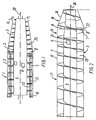
- the decanter centrifuge 1 in Fig. 1 has a hollow bowl 2 with a separation chamber containing a screw conveyor 3 having a body 4 with a screw with a flight 7, which is wound in a number of turns.
- the body 4 is substantially cylindrical and has a conical part 5 at one end.
- inlet openings 6 for the material to be separated are provided, and in the bowl 2 discharge openings 14 for the separated heavy phase are provided.
- the light phase 12 will be positioned closest to the body of the screw conveyor 4, whereas the heavy phase 13 is positioned at the interior side of the bowl 2.
- the light phase is taken away via a discharge edge 10 on the bowl.
- the heavy phase is conveyed by the screw turn towards the discharge openings 14 in the bowl at its conical end.
- the figure shows a baffle 8 comprising an annular disc, which is perpendicular to the longitudinal axis or axial direction of the screw conveyor.
- Fig. 2 shows a screw conveyor 3, which as the screw conveyor in Fig. 1 is provided with a baffle 8 in the form of an annular disc and an inlet opening 6.
- Fig. 2 shows by broken lines the enveloping surface for the screw turns of the flight 7.
- the enveloping surface comprises a cylindrical part 15 and a conical part 16.
- the enveloping surface corresponds with a suitable clear to the shape of the bowl, in which the screw conveyor is to be mounted.
- the baffle 8 is positioned near the transition between the conical part 16 and the cylindrical part 15, and it divides substantially the centrifuge or the separation chamber in a cylindrical separation part 17 and a conical discharge part 18.
- the discharge part 18 comprises, however, a small portion of the cylindrical part 15.
- the pitch of the screw turns varies along the screw conveyor 3 in its axial direction 20.
- the position 21 marks, on account of the change constituted by the leap, a dividing line between the separation part 17 and a transition part 19 between the separation part 17 and the discharge part 18.
- the pitch is in the embodiment constant from the position 21 to the discharge openings for the heavy phase.
- the pitch of the screw turns in the separation part 17 is in this example decreasing in the axial direction 20 such that the pitch is smallest immediately before the transition part 19.
- the inlet 6 is situated in the separation part 17 shortly before the transition part 19.
- Fig. 3 shows another embodiment having a baffle 8 extending axially.
- the flight 7 of the screw conveyor 3 has in the position 21 a leap of the pitch, which is consequently bigger in the transition part 19 than in the separation part 17.
- the pitch is constant.
- the dividing line between the transition part 19 and the discharge part 18 is considered to lie at the axial centre point 23 of the baffle.
- the position 21 is somewhat downstream of the starting point 24 of the baffle, the position 21 will lie slightly more than a half pitch before the centre point 23 of the baffle.
- the pitch of the flight 7 is, in the screw conveyors described up till now, equal to the axial dimension of the passageway 25 formed between the adjacent turns of the flight 7, and the pitch angle of the flight 7 in the separation part 17 is substantially smaller than 45° relative to the tangential direction.
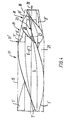
- Fig. 4 shows an embodiment, in which the screw of the screw conveyor 3 has three flights 7' having a pitch angle substantially bigger than 45° relative to the tangential direction in the separation part 17. At an axial position 21' the pitch is changed, the pitch angle being changed in direction of 45°, following which the nominal transport speed increases.
- baffle member 8' extends from each flight 7', said baffle member extending as a part of a turn having a higher pitch than the flights 7' in the transition part 19 and the discharge part 18, but with the same rotational direction such that the baffle members 8' extend from a downstream side surface 26 of a flight 7' to an upstream side surface 27 of an adjacent flight 7'.
- the baffle members 8' have the same pitch as the flights 7' in the separation part, but that need not be the case.
- a centrifuge with a screw conveyor according to the invention works in the following way.
- Material to be separated for example aqueous sludge
- aqueous sludge is led into the separation chamber through the inlet 6.
- the sludge flows through the passageway 25 established by the flight 7 of the screw turn, or the passageways 25 established by the flights 7', towards the left of the figures.
- the heavy phase sediments i.e. the sludge, as indicated in Fig. 1.
- the screw conveyor 3 pulls on account of its rotation relative to the bowl 2 the sedimented sludge to the right of the figures (downstream direction).
- the sludge is compressed in the separation part 15 up to the axial position 21. At this point, the sludge forms a coherent, comparatively dry cake.
- the position 21 is in the embodiment in Fig. 2 positioned approximately 2/3 turn before the intersection point 21 of the screw turn 7 with the baffle 8 corresponding to an axial distance between the position 21 and the point 22 of 2/3 of the pitch of the screw turn or the axial dimension of the passageway at this point.
- the position 21 is positioned a little bit more than 1/2 time the axial dimension of the passageway 25 upstream of the axial centre point 23 of the baffle 8 or the baffle members 8'. In this manner the changing point of the transport speed is situated sufficiently far from the baffle 8, 8' to convey the sludge along the periphery of the entire baffle at the increased speed.
- the space between the periphery of the baffle 8 and the interior wall of the bowl 2 is smaller than the thickness of the sludge at the point 21.
- the increased speed in the transition part 19 compensates to a certain degree for this difference.
- compensation is somewhat below 100%, as a compensation of 100% or more could entail the risk that the sludge cake might be pulled to pieces, which may result in a break through of the light phase under and past the baffle 8.
- the increased speed also compensates for the reduced cross-section area of the conical part of the bowl 2 in the discharge part 18.
Landscapes
- Centrifugal Separators (AREA)
- Medicines Containing Material From Animals Or Micro-Organisms (AREA)
- Extraction Or Liquid Replacement (AREA)
Applications Claiming Priority (3)
| Application Number | Priority Date | Filing Date | Title |
|---|---|---|---|
| DK200200598A DK200200598A (da) | 2002-04-22 | 2002-04-22 | Dekantercentrifuge |
| DK200200598 | 2002-04-22 | ||
| PCT/DK2003/000235 WO2003089146A1 (en) | 2002-04-22 | 2003-04-09 | A decanter centrifuge |
Publications (2)
| Publication Number | Publication Date |
|---|---|
| EP1497033A1 EP1497033A1 (en) | 2005-01-19 |
| EP1497033B1 true EP1497033B1 (en) | 2008-01-23 |
Family
ID=29225557
Family Applications (1)
| Application Number | Title | Priority Date | Filing Date |
|---|---|---|---|
| EP03746811A Expired - Lifetime EP1497033B1 (en) | 2002-04-22 | 2003-04-09 | A decanter centrifuge |
Country Status (21)
| Country | Link |
|---|---|
| US (1) | US7156801B2 (pl) |
| EP (1) | EP1497033B1 (pl) |
| JP (1) | JP4387202B2 (pl) |
| KR (1) | KR100943692B1 (pl) |
| CN (1) | CN1287901C (pl) |
| AT (1) | ATE384582T1 (pl) |
| AU (1) | AU2003226930B2 (pl) |
| BR (1) | BR0309069B1 (pl) |
| CA (1) | CA2480715C (pl) |
| DE (1) | DE60318833T2 (pl) |
| DK (2) | DK200200598A (pl) |
| ES (1) | ES2299716T3 (pl) |
| IL (2) | IL164024A0 (pl) |
| MX (1) | MXPA04010355A (pl) |
| NO (1) | NO334185B1 (pl) |
| NZ (1) | NZ535208A (pl) |
| PL (1) | PL198688B1 (pl) |
| PT (1) | PT1497033E (pl) |
| RU (1) | RU2279924C2 (pl) |
| WO (1) | WO2003089146A1 (pl) |
| ZA (1) | ZA200407109B (pl) |
Families Citing this family (26)
| Publication number | Priority date | Publication date | Assignee | Title |
|---|---|---|---|---|
| DK200200598A (da) * | 2002-04-22 | 2003-10-23 | Alfa Laval Copenhagen As | Dekantercentrifuge |
| SE525413C2 (sv) * | 2003-06-18 | 2005-02-15 | Alfa Laval Corp Ab | En skruvtransportör för en dekantercentrifug |
| DE10336350B4 (de) * | 2003-08-08 | 2007-10-31 | Westfalia Separator Ag | Vollmantel-Schneckenzentrifuge, mit Schälscheibe |
| JP4093586B1 (ja) * | 2007-02-23 | 2008-06-04 | 株式会社プラントコンストラクトアンドエンジニアリング | 物質移送装置 |
| CA2626814C (en) * | 2007-03-23 | 2014-04-29 | Rod Wick | Apparatus and methods for remediating drill cuttings and other particulate materials |
| CN101402072B (zh) * | 2008-08-14 | 2012-07-04 | 浙江辰鑫机械设备有限公司 | 卧螺离心机 |
| DK200970028A (en) * | 2009-06-12 | 2010-12-13 | Alfa Laval Corp Ab | A decanter centrifuge and a screw conveyor |
| RU2417844C1 (ru) * | 2009-10-22 | 2011-05-10 | Алексей Георгиевич Трошин | Центрифуга с непрерывной выгрузкой осадка |
| CN103443577B (zh) * | 2010-07-01 | 2016-05-25 | 森特瑞斯公司 | 使多相固体在重相排放流中高效地流动的离心液体分离机 |
| CN102824966B (zh) * | 2012-07-31 | 2014-08-13 | 天圣环保工程(成都)有限公司 | 一种螺旋推料器及其应用的卧螺离心机 |
| US9826757B2 (en) | 2013-03-15 | 2017-11-28 | Advance International Inc. | Automated method and system for recovering protein powder meal, pure omega 3 oil and purified distilled water from animal tissue |
| EP3009193A4 (en) * | 2013-06-14 | 2017-02-22 | TOMOE Engineering Co., Ltd. | Centrifuge |
| JP6278307B2 (ja) * | 2014-01-14 | 2018-02-14 | 三菱重工環境・化学エンジニアリング株式会社 | 遠心脱水装置 |
| JP5667724B1 (ja) * | 2014-08-20 | 2015-02-12 | 巴工業株式会社 | デカンタ型遠心分離機及びデカンタ型遠心分離機の運転方法 |
| NO338067B1 (no) * | 2014-11-10 | 2016-07-25 | Vetco Gray Scandinavia As | Aktivt roterende separator for multifasefluider med elektrisk motor montert koaksialt med en separatortrommel |
| CA2920789C (en) | 2015-06-04 | 2021-05-18 | Advance International, Inc. | Improved methods and systems for recovering protein powder and natural omega-3 oil from animal tissue |
| RU2649448C1 (ru) * | 2017-01-17 | 2018-04-03 | Георгий Петрович Трошин | Центрифуга осадительная |
| DE102017103067A1 (de) | 2017-02-15 | 2018-08-16 | Flottweg Se | Vollmantelschneckenzentrifugen-Schnecke mit einer Schneckenwendel |
| CA3057084C (en) | 2019-01-09 | 2025-05-20 | Jeremy Leonard | CENTRIFUGAL SEPARATOR |
| CN112811778B (zh) * | 2021-02-08 | 2024-11-05 | 福建云康智能科技有限公司 | 一种具有异形中心轴的螺旋轴的固液分离装置 |
| CN113998859A (zh) * | 2021-11-15 | 2022-02-01 | 浙江问源环保科技股份有限公司 | 一种污泥深度脱水处理系统 |
| EP4563231A1 (en) | 2023-11-30 | 2025-06-04 | Alfa Laval Corporate AB | A decanter centrifuge for separating feed material |
| EP4563232A1 (en) | 2023-11-30 | 2025-06-04 | Alfa Laval Corporate AB | A decanter centrifuge for separating feed material |
| WO2025114493A1 (en) | 2023-11-30 | 2025-06-05 | Alfa Laval Corporate Ab | A decanter centrifuge for separating feed material |
| EP4563233A1 (en) | 2023-11-30 | 2025-06-04 | Alfa Laval Corporate AB | A decanter centrifuge for separating feed material |
| EP4563234A1 (en) | 2023-11-30 | 2025-06-04 | Alfa Laval Corporate AB | A decanter centrifuge for separating feed material |
Family Cites Families (24)
| Publication number | Priority date | Publication date | Assignee | Title |
|---|---|---|---|---|
| US1383313A (en) * | 1920-06-24 | 1921-07-05 | Clarence P Landreth | Centrifugal apparatus |
| NO120465B (pl) * | 1965-10-21 | 1970-10-19 | Alfa Laval Ab | |
| US3430850A (en) * | 1967-11-13 | 1969-03-04 | Perfection Eng Co Inc | Centrifugal separator |
| US3795361A (en) * | 1972-09-06 | 1974-03-05 | Pennwalt Corp | Centrifuge apparatus |
| AR205952A1 (es) * | 1975-01-03 | 1976-06-15 | Pennwalt Corp | Una centrifuga decantadora |
| DE2907318A1 (de) | 1979-02-24 | 1980-08-28 | Bayer Ag | Vollmantelschneckenzentrifuge mit angepasster schneckenwendel |
| US4245777A (en) * | 1979-08-30 | 1981-01-20 | Pennwalt Corporation | Centrifuge apparatus |
| DE3027020A1 (de) * | 1980-07-17 | 1982-02-04 | Klöckner-Humboldt-Deutz AG, 5000 Köln | Vollmantelzentrifuge zum stoffaustausch zwischen fluessigkeiten |
| US4381849A (en) * | 1981-06-29 | 1983-05-03 | Bird Machine Company, Inc. | Solids-liquid slurry separating centrifuge |
| DE3335873A1 (de) * | 1983-07-25 | 1985-02-21 | Klöckner-Humboldt-Deutz AG, 5000 Köln | Vollmantel-schneckenzentrifuge zur trennung eines feststoff-fluessigkeitsgemisches |
| US4731182A (en) * | 1985-11-18 | 1988-03-15 | Decanter Pty. Limited | Decanter centrifuge |
| DE3921328A1 (de) * | 1989-06-29 | 1991-01-10 | Kloeckner Humboldt Deutz Ag | Verfahren und vorrichtung zur nachbehandlung des dickstoffes im dickstoffaustragsbereich einer vollmantel-schneckenzentrifuge |
| JP3032283B2 (ja) * | 1990-11-27 | 2000-04-10 | 月島機械株式会社 | デカンタ型遠心分離機 |
| DE4041923A1 (de) * | 1990-12-27 | 1992-07-02 | Kloeckner Humboldt Deutz Ag | Vollmantel-schneckenzentrifuge |
| GB9225067D0 (en) * | 1992-12-01 | 1993-01-20 | Broadbent & Sons Ltd Thomas | Decanting-type centrifuges |
| US5354255A (en) * | 1992-12-17 | 1994-10-11 | Alfa Laval Separation Inc. | Decanter centrifuge with conveyor capable of high speed and higher flow rates |
| US5653673A (en) * | 1994-06-27 | 1997-08-05 | Amoco Corporation | Wash conduit configuration in a centrifuge apparatus and uses thereof |
| DK143295A (da) | 1995-12-18 | 1997-06-19 | Tetra Laval Holdings & Finance | Dekantercentrifuge |
| SE505557C2 (sv) * | 1995-12-21 | 1997-09-15 | Alfa Laval Separation Ab | Dekantercentrifug |
| DE69704963T2 (de) * | 1996-01-18 | 2002-01-24 | Rapanelli Fioravante S.P.A., Foligno | Horizontale Zentrifuge für eine optimale Ölextraktion |
| JP3336291B2 (ja) * | 1999-05-21 | 2002-10-21 | 巴工業株式会社 | デカンタ型遠心分離機 |
| US6572524B1 (en) * | 2000-07-14 | 2003-06-03 | Alfa Laval Inc. | Decanter centrifuge having a heavy phase solids baffle |
| DE10125096A1 (de) * | 2001-05-23 | 2002-11-28 | Hiller Gmbh | Dekantierzentrifuge |
| DK200200598A (da) * | 2002-04-22 | 2003-10-23 | Alfa Laval Copenhagen As | Dekantercentrifuge |
-
2002
- 2002-04-22 DK DK200200598A patent/DK200200598A/da not_active Application Discontinuation
-
2003
- 2003-04-09 IL IL16402403A patent/IL164024A0/xx unknown
- 2003-04-09 DK DK03746811T patent/DK1497033T3/da active
- 2003-04-09 ES ES03746811T patent/ES2299716T3/es not_active Expired - Lifetime
- 2003-04-09 BR BRPI0309069-8B1A patent/BR0309069B1/pt active IP Right Grant
- 2003-04-09 JP JP2003585887A patent/JP4387202B2/ja not_active Expired - Lifetime
- 2003-04-09 AT AT03746811T patent/ATE384582T1/de not_active IP Right Cessation
- 2003-04-09 DE DE60318833T patent/DE60318833T2/de not_active Expired - Lifetime
- 2003-04-09 AU AU2003226930A patent/AU2003226930B2/en not_active Expired
- 2003-04-09 RU RU2004133889/12A patent/RU2279924C2/ru active
- 2003-04-09 US US10/509,836 patent/US7156801B2/en not_active Expired - Lifetime
- 2003-04-09 MX MXPA04010355A patent/MXPA04010355A/es active IP Right Grant
- 2003-04-09 PL PL373320A patent/PL198688B1/pl unknown
- 2003-04-09 KR KR1020047016875A patent/KR100943692B1/ko not_active Expired - Lifetime
- 2003-04-09 CA CA2480715A patent/CA2480715C/en not_active Expired - Lifetime
- 2003-04-09 PT PT03746811T patent/PT1497033E/pt unknown
- 2003-04-09 EP EP03746811A patent/EP1497033B1/en not_active Expired - Lifetime
- 2003-04-09 WO PCT/DK2003/000235 patent/WO2003089146A1/en not_active Ceased
- 2003-04-09 CN CNB038090686A patent/CN1287901C/zh not_active Expired - Lifetime
- 2003-04-09 NZ NZ535208A patent/NZ535208A/en not_active IP Right Cessation
-
2004
- 2004-09-06 ZA ZA2004/07109A patent/ZA200407109B/en unknown
- 2004-09-12 IL IL164024A patent/IL164024A/en active IP Right Revival
- 2004-11-22 NO NO20045062A patent/NO334185B1/no not_active IP Right Cessation
Also Published As
Similar Documents
| Publication | Publication Date | Title |
|---|---|---|
| EP1497033B1 (en) | A decanter centrifuge | |
| EP2551021B1 (en) | Centrifuge and discharge port member of a centrifuge for power reduction | |
| RU98113930A (ru) | Декантирующая центрифуга | |
| AU2002221724B2 (en) | Solid-bowl screw centrifuge | |
| CA2480852A1 (en) | Centrifuges and methods of separating feed material | |
| US10293346B2 (en) | Screw conveyor for a centrifugal separator including partition walls in the helical channel | |
| EP1330313A1 (en) | Pump vanes for a decanter centrifuge feed chamber | |
| WO2002005966A3 (en) | Decanter centrifuge having a heavy phase solids baffle | |
| FI67590B (fi) | Virvelrenare | |
| AU2001230553B2 (en) | Centrifugal separator | |
| GB2083381A (en) | Uniflow decanter centrifuge | |
| KR100345302B1 (ko) | 다중 에젝터를 이용한 분리기 | |
| WO1995026233A1 (en) | Cyclone inlet unit | |
| SE524032C2 (sv) | Anordning och förfarande vid framställning av pappersmassa | |
| CA2240167A1 (en) | A decanter centrifuge |
Legal Events
| Date | Code | Title | Description |
|---|---|---|---|
| PUAI | Public reference made under article 153(3) epc to a published international application that has entered the european phase |
Free format text: ORIGINAL CODE: 0009012 |
|
| 17P | Request for examination filed |
Effective date: 20040902 |
|
| AK | Designated contracting states |
Kind code of ref document: A1 Designated state(s): AT BE BG CH CY CZ DE DK EE ES FI FR GB GR HU IE IT LI LU MC NL PT RO SE SI SK TR |
|
| AX | Request for extension of the european patent |
Extension state: AL LT LV MK |
|
| GRAP | Despatch of communication of intention to grant a patent |
Free format text: ORIGINAL CODE: EPIDOSNIGR1 |
|
| GRAS | Grant fee paid |
Free format text: ORIGINAL CODE: EPIDOSNIGR3 |
|
| GRAA | (expected) grant |
Free format text: ORIGINAL CODE: 0009210 |
|
| AK | Designated contracting states |
Kind code of ref document: B1 Designated state(s): AT BE BG CH CY CZ DE DK EE ES FI FR GB GR HU IE IT LI LU MC NL PT RO SE SI SK TR |
|
| AX | Request for extension of the european patent |
Extension state: AL LT LV MK |
|
| REG | Reference to a national code |
Ref country code: GB Ref legal event code: FG4D |
|
| REG | Reference to a national code |
Ref country code: CH Ref legal event code: EP |
|
| REG | Reference to a national code |
Ref country code: IE Ref legal event code: FG4D |
|
| REG | Reference to a national code |
Ref country code: PT Ref legal event code: SC4A Free format text: AVAILABILITY OF NATIONAL TRANSLATION Effective date: 20080227 |
|
| REF | Corresponds to: |
Ref document number: 60318833 Country of ref document: DE Date of ref document: 20080313 Kind code of ref document: P |
|
| REG | Reference to a national code |
Ref country code: GR Ref legal event code: EP Ref document number: 20080400875 Country of ref document: GR |
|
| REG | Reference to a national code |
Ref country code: DK Ref legal event code: T3 |
|
| REG | Reference to a national code |
Ref country code: SE Ref legal event code: TRGR |
|
| REG | Reference to a national code |
Ref country code: CH Ref legal event code: NV Representative=s name: BOHEST AG |
|
| REG | Reference to a national code |
Ref country code: ES Ref legal event code: FG2A Ref document number: 2299716 Country of ref document: ES Kind code of ref document: T3 |
|
| PG25 | Lapsed in a contracting state [announced via postgrant information from national office to epo] |
Ref country code: BG Free format text: LAPSE BECAUSE OF FAILURE TO SUBMIT A TRANSLATION OF THE DESCRIPTION OR TO PAY THE FEE WITHIN THE PRESCRIBED TIME-LIMIT Effective date: 20080423 Ref country code: AT Free format text: LAPSE BECAUSE OF FAILURE TO SUBMIT A TRANSLATION OF THE DESCRIPTION OR TO PAY THE FEE WITHIN THE PRESCRIBED TIME-LIMIT Effective date: 20080123 |
|
| ET | Fr: translation filed | ||
| PG25 | Lapsed in a contracting state [announced via postgrant information from national office to epo] |
Ref country code: SI Free format text: LAPSE BECAUSE OF FAILURE TO SUBMIT A TRANSLATION OF THE DESCRIPTION OR TO PAY THE FEE WITHIN THE PRESCRIBED TIME-LIMIT Effective date: 20080123 |
|
| PG25 | Lapsed in a contracting state [announced via postgrant information from national office to epo] |
Ref country code: SK Free format text: LAPSE BECAUSE OF FAILURE TO SUBMIT A TRANSLATION OF THE DESCRIPTION OR TO PAY THE FEE WITHIN THE PRESCRIBED TIME-LIMIT Effective date: 20080123 |
|
| PG25 | Lapsed in a contracting state [announced via postgrant information from national office to epo] |
Ref country code: RO Free format text: LAPSE BECAUSE OF FAILURE TO SUBMIT A TRANSLATION OF THE DESCRIPTION OR TO PAY THE FEE WITHIN THE PRESCRIBED TIME-LIMIT Effective date: 20080123 Ref country code: MC Free format text: LAPSE BECAUSE OF NON-PAYMENT OF DUE FEES Effective date: 20080430 |
|
| PLBE | No opposition filed within time limit |
Free format text: ORIGINAL CODE: 0009261 |
|
| STAA | Information on the status of an ep patent application or granted ep patent |
Free format text: STATUS: NO OPPOSITION FILED WITHIN TIME LIMIT |
|
| 26N | No opposition filed |
Effective date: 20081024 |
|
| PG25 | Lapsed in a contracting state [announced via postgrant information from national office to epo] |
Ref country code: EE Free format text: LAPSE BECAUSE OF FAILURE TO SUBMIT A TRANSLATION OF THE DESCRIPTION OR TO PAY THE FEE WITHIN THE PRESCRIBED TIME-LIMIT Effective date: 20080123 |
|
| PG25 | Lapsed in a contracting state [announced via postgrant information from national office to epo] |
Ref country code: IE Free format text: LAPSE BECAUSE OF NON-PAYMENT OF DUE FEES Effective date: 20080409 |
|
| PG25 | Lapsed in a contracting state [announced via postgrant information from national office to epo] |
Ref country code: CY Free format text: LAPSE BECAUSE OF FAILURE TO SUBMIT A TRANSLATION OF THE DESCRIPTION OR TO PAY THE FEE WITHIN THE PRESCRIBED TIME-LIMIT Effective date: 20080123 |
|
| PG25 | Lapsed in a contracting state [announced via postgrant information from national office to epo] |
Ref country code: HU Free format text: LAPSE BECAUSE OF FAILURE TO SUBMIT A TRANSLATION OF THE DESCRIPTION OR TO PAY THE FEE WITHIN THE PRESCRIBED TIME-LIMIT Effective date: 20080724 Ref country code: LU Free format text: LAPSE BECAUSE OF NON-PAYMENT OF DUE FEES Effective date: 20080409 |
|
| REG | Reference to a national code |
Ref country code: CH Ref legal event code: PCAR Free format text: NEW ADDRESS: HOLBEINSTRASSE 36-38, 4051 BASEL (CH) |
|
| REG | Reference to a national code |
Ref country code: FR Ref legal event code: PLFP Year of fee payment: 13 |
|
| REG | Reference to a national code |
Ref country code: FR Ref legal event code: PLFP Year of fee payment: 14 |
|
| REG | Reference to a national code |
Ref country code: FR Ref legal event code: PLFP Year of fee payment: 15 |
|
| REG | Reference to a national code |
Ref country code: FR Ref legal event code: PLFP Year of fee payment: 16 |
|
| PGFP | Annual fee paid to national office [announced via postgrant information from national office to epo] |
Ref country code: GB Payment date: 20220303 Year of fee payment: 20 Ref country code: CH Payment date: 20220314 Year of fee payment: 20 |
|
| PGFP | Annual fee paid to national office [announced via postgrant information from national office to epo] |
Ref country code: SE Payment date: 20220228 Year of fee payment: 20 Ref country code: NL Payment date: 20220314 Year of fee payment: 20 Ref country code: IT Payment date: 20220310 Year of fee payment: 20 Ref country code: GR Payment date: 20220316 Year of fee payment: 20 Ref country code: FR Payment date: 20220308 Year of fee payment: 20 Ref country code: CZ Payment date: 20220317 Year of fee payment: 20 Ref country code: BE Payment date: 20220321 Year of fee payment: 20 |
|
| PGFP | Annual fee paid to national office [announced via postgrant information from national office to epo] |
Ref country code: PT Payment date: 20220407 Year of fee payment: 20 Ref country code: ES Payment date: 20220506 Year of fee payment: 20 Ref country code: DK Payment date: 20220412 Year of fee payment: 20 Ref country code: DE Payment date: 20220302 Year of fee payment: 20 |
|
| PGFP | Annual fee paid to national office [announced via postgrant information from national office to epo] |
Ref country code: TR Payment date: 20220407 Year of fee payment: 20 Ref country code: FI Payment date: 20220412 Year of fee payment: 20 |
|
| REG | Reference to a national code |
Ref country code: DE Ref legal event code: R071 Ref document number: 60318833 Country of ref document: DE |
|
| REG | Reference to a national code |
Ref country code: DK Ref legal event code: EUP Expiry date: 20230409 |
|
| REG | Reference to a national code |
Ref country code: NL Ref legal event code: MK Effective date: 20230408 |
|
| REG | Reference to a national code |
Ref country code: CH Ref legal event code: PL |
|
| PG25 | Lapsed in a contracting state [announced via postgrant information from national office to epo] |
Ref country code: CZ Free format text: LAPSE BECAUSE OF EXPIRATION OF PROTECTION Effective date: 20230409 |
|
| REG | Reference to a national code |
Ref country code: ES Ref legal event code: FD2A Effective date: 20230428 |
|
| REG | Reference to a national code |
Ref country code: BE Ref legal event code: MK Effective date: 20230409 |
|
| REG | Reference to a national code |
Ref country code: GB Ref legal event code: PE20 Expiry date: 20230408 |
|
| REG | Reference to a national code |
Ref country code: SE Ref legal event code: EUG |
|
| P01 | Opt-out of the competence of the unified patent court (upc) registered |
Effective date: 20230325 |
|
| PG25 | Lapsed in a contracting state [announced via postgrant information from national office to epo] |
Ref country code: PT Free format text: LAPSE BECAUSE OF EXPIRATION OF PROTECTION Effective date: 20230420 Ref country code: ES Free format text: LAPSE BECAUSE OF EXPIRATION OF PROTECTION Effective date: 20230410 |
|
| PG25 | Lapsed in a contracting state [announced via postgrant information from national office to epo] |
Ref country code: GB Free format text: LAPSE BECAUSE OF EXPIRATION OF PROTECTION Effective date: 20230408 |