EP1496175B1 - Schlüsselsystem für ein Kraftfahrzeug - Google Patents
Schlüsselsystem für ein Kraftfahrzeug Download PDFInfo
- Publication number
- EP1496175B1 EP1496175B1 EP04014221A EP04014221A EP1496175B1 EP 1496175 B1 EP1496175 B1 EP 1496175B1 EP 04014221 A EP04014221 A EP 04014221A EP 04014221 A EP04014221 A EP 04014221A EP 1496175 B1 EP1496175 B1 EP 1496175B1
- Authority
- EP
- European Patent Office
- Prior art keywords
- key
- motor vehicle
- latching
- emergency key
- locking
- Prior art date
- Legal status (The legal status is an assumption and is not a legal conclusion. Google has not performed a legal analysis and makes no representation as to the accuracy of the status listed.)
- Expired - Lifetime
Links
Images




Classifications
-
- G—PHYSICS
- G07—CHECKING-DEVICES
- G07C—TIME OR ATTENDANCE REGISTERS; REGISTERING OR INDICATING THE WORKING OF MACHINES; GENERATING RANDOM NUMBERS; VOTING OR LOTTERY APPARATUS; ARRANGEMENTS, SYSTEMS OR APPARATUS FOR CHECKING NOT PROVIDED FOR ELSEWHERE
- G07C9/00—Individual registration on entry or exit
- G07C9/00174—Electronically operated locks; Circuits therefor; Nonmechanical keys therefor, e.g. passive or active electrical keys or other data carriers without mechanical keys
- G07C9/00944—Details of construction or manufacture
-
- B—PERFORMING OPERATIONS; TRANSPORTING
- B60—VEHICLES IN GENERAL
- B60R—VEHICLES, VEHICLE FITTINGS, OR VEHICLE PARTS, NOT OTHERWISE PROVIDED FOR
- B60R25/00—Fittings or systems for preventing or indicating unauthorised use or theft of vehicles
- B60R25/20—Means to switch the anti-theft system on or off
- B60R25/24—Means to switch the anti-theft system on or off using electronic identifiers containing a code not memorised by the user
-
- B—PERFORMING OPERATIONS; TRANSPORTING
- B60—VEHICLES IN GENERAL
- B60R—VEHICLES, VEHICLE FITTINGS, OR VEHICLE PARTS, NOT OTHERWISE PROVIDED FOR
- B60R25/00—Fittings or systems for preventing or indicating unauthorised use or theft of vehicles
- B60R25/20—Means to switch the anti-theft system on or off
- B60R25/24—Means to switch the anti-theft system on or off using electronic identifiers containing a code not memorised by the user
- B60R25/243—Means to switch the anti-theft system on or off using electronic identifiers containing a code not memorised by the user with more than one way to gain access
-
- E—FIXED CONSTRUCTIONS
- E05—LOCKS; KEYS; WINDOW OR DOOR FITTINGS; SAFES
- E05B—LOCKS; ACCESSORIES THEREFOR; HANDCUFFS
- E05B19/00—Keys; Accessories therefor
- E05B19/0082—Keys or shanks being removably stored in a larger object, e.g. a remote control or a key fob
-
- E—FIXED CONSTRUCTIONS
- E05—LOCKS; KEYS; WINDOW OR DOOR FITTINGS; SAFES
- E05B—LOCKS; ACCESSORIES THEREFOR; HANDCUFFS
- E05B19/00—Keys; Accessories therefor
- E05B19/04—Construction of the bow or head of the key; Attaching the bow to the shank
- E05B19/046—Construction of the bow or head of the key; Attaching the bow to the shank the shank being slidingly mounted on the bow, e.g. for storage
-
- G—PHYSICS
- G07—CHECKING-DEVICES
- G07C—TIME OR ATTENDANCE REGISTERS; REGISTERING OR INDICATING THE WORKING OF MACHINES; GENERATING RANDOM NUMBERS; VOTING OR LOTTERY APPARATUS; ARRANGEMENTS, SYSTEMS OR APPARATUS FOR CHECKING NOT PROVIDED FOR ELSEWHERE
- G07C9/00—Individual registration on entry or exit
- G07C9/00174—Electronically operated locks; Circuits therefor; Nonmechanical keys therefor, e.g. passive or active electrical keys or other data carriers without mechanical keys
- G07C9/00944—Details of construction or manufacture
- G07C2009/00952—Electronic keys comprising a mechanical key within their housing, e.g. extractable or retractable emergency key
-
- G—PHYSICS
- G07—CHECKING-DEVICES
- G07C—TIME OR ATTENDANCE REGISTERS; REGISTERING OR INDICATING THE WORKING OF MACHINES; GENERATING RANDOM NUMBERS; VOTING OR LOTTERY APPARATUS; ARRANGEMENTS, SYSTEMS OR APPARATUS FOR CHECKING NOT PROVIDED FOR ELSEWHERE
- G07C9/00—Individual registration on entry or exit
- G07C9/00174—Electronically operated locks; Circuits therefor; Nonmechanical keys therefor, e.g. passive or active electrical keys or other data carriers without mechanical keys
- G07C2009/00968—Electronically operated locks; Circuits therefor; Nonmechanical keys therefor, e.g. passive or active electrical keys or other data carriers without mechanical keys shape of the data carrier
Definitions
- the invention relates to a key system for a motor vehicle with a transmission electronics arranged in a housing for non-contact locking and / or unlocking a door of the motor vehicle and / or operation of the motor vehicle and with an emergency key for mechanically locking and / or unlocking the door Motor vehicle and / or the operation of the motor vehicle.
- a key system for a motor vehicle with a housing arranged in a transmission electronics for contactless locking and / or unlocking a door of the motor vehicle and / or operation of the motor vehicle and an emergency key for mechanically locking and / or unlocking the door Motor vehicle and / or to operate the motor vehicle solved, wherein the emergency key at least a first notch, by means of the emergency key is locked in a first detent position in the housing, and a second notch, by means of the emergency key in a different from the first detent second Locking position can be locked in the housing, wherein the housing has a cooperating both with the first notch and with the second notch of the notch locking mechanism for locking the emergency key in the first and in the second detent position.
- a notch instead of a notch, other mechanically equivalent geometries, such as bulges, possible, which can be understood as notches in the context of the invention.
- a notch a counterpart to the locking mechanism is achieved, which requires less effort compared to a bulge in the mechanical locking of the emergency key.
- an opening for threading a key ring by a locking mechanism as a notch for locking the emergency key, in particular in the first detent position is usable.
- Motor vehicle in the sense of the invention is in particular a land vehicle which can be used individually in road traffic.
- Motor vehicles according to the invention are not limited in particular to land vehicles with internal combustion engine.
- a door (of a motor vehicle) in the sense of the invention may in particular be a door, a rear or front flap or a boot lid.
- a trained for mechanical operation of the motor vehicle emergency key according to the invention corresponds in particular to a mechanical key.
- the latching mechanism has a locking ball which can be pressed into the first notch in order to lock the emergency key in the first latching position, in particular by means of a spring.
- the locking ball for locking the emergency key in the second detent position in particular by means of a spring, can be pressed into the second notch.
- the latching mechanism on a locking pin which is depressible for locking the emergency key in the first detent position, in particular by means of a spring in the first notch.
- the locking pin is pressed in a further advantageous embodiment of the invention for locking the emergency key in the second detent position, in particular by means of a spring in the second notch.
- the latching mechanism has a latching hook, which is used for locking the emergency key in the first latching position, in particular by means of an elastic element, such as. a so-called 'crackpot frog', in the first notch is pressed.
- the latching hook for locking the emergency key in the second latching position, in particular by means of the elastic element in the second notch can be pressed.
- the latching hook can be pressed by pressure on the elastic element from the first notch and by pressure on the elastic element from the second notch.
- the latching mechanism on a detent which is for locking the emergency key in the first detent position in the first Notch is pressed, wherein the first notch is designed as an opening for receiving a key ring.
- the detent for locking the emergency key in the second detent position in the second notch can be pressed.
- the key system at least one resilient element, in particular a coil spring or a plastic piece, on, by means of which the emergency key at least z.T. from the housing is slidable when the locking mechanism is in a released position.
- the resilient element may be made substantially of plastic, e.g. Silicone, insist.
- the resilient element is advantageously arranged in the housing.
- the emergency key is slidable by means of the resilient element from the first detent position to the second detent position when the detent mechanism is in a released position, wherein the resilient element in a further advantageous embodiment of the invention by inserting the emergency key into the housing is tensionable.
- the housing advantageously has a height of less than 20mm, in particular less than 18mm. It can be provided that, moreover, the overall height at an end face of the housing is smaller by about 5 mm than the overall height of the opposite end face of the housing.
- a key system for a motor vehicle with a transmission electronics arranged in a housing for non-contact locking and / or unlocking a door of the motor vehicle and / or operation of the motor vehicle and with an emergency key to mechanically locking and / or unlocking the door of the motor vehicle and / or for operating the motor vehicle, the housing having a latching mechanism for locking the emergency key in a first latching position and a second latching position different from the first latching position and a resilient element, by means of which the emergency key is slidable from the first detent position to the second detent position when the detent mechanism is in a released position.
- the key system 1 shows an exemplary embodiment of a key system 1 for a motor vehicle located in a first arresting position.
- the key system 1 has a transmission electronics arranged in a housing 2 for non-contact locking and / or unlocking a door of the motor vehicle and / or operation of the motor vehicle and an emergency key 3 for mechanically locking and / or unlocking the door of the motor vehicle and / or for the operation of the motor vehicle.
- a thrust element 4 is also provided.
- Fig. 2 shows the emergency key 3 in three-dimensional representation.
- the emergency key 3 has a closing body 6 and a receiving body 5 suitable for receiving a key ring with an oval opening 11.
- the closing body 6 has a closing piece 10 for mechanically locking and / or unlocking the door of the motor vehicle and / or for operating the motor vehicle and a holding body 9, on which the closing piece 10 is fastened.
- the closing body 6 and the receiving body 5 are tiltably connected to each other by means of a hinge 12.
- the closing body 6 also has a first notch 7 and a second notch 8.
- Fig. 3 shows an alternative to the emergency key 3 embodiment of an emergency key 20 in three-dimensional representation.
- the emergency key 20 has a closing body 26 and a receiving body 25 suitable for receiving a key ring with a circular opening 21 in contrast to the opening 11.
- the closing body 26 has a closing piece 23 for mechanically locking and / or unlocking the door of the motor vehicle and / or for operating the motor vehicle and a holding body 29, to which the closing piece 23 is fastened.
- the closing body 26 and the receiving body 25 are tiltably connected to each other by means of a hinge 22.
- the closing body 26 also has a first notch 27 and a second notch 28.
- Fig. 2 and Fig. 3 also show exemplary dimensions in mm.
- Fig. 4 shows the embodiment of the key system 1 according to FIG. 1 in a cut-three-dimensional representation.
- the emergency key 3 is completely received in an inner space 30 of the housing 2.
- Fig. 5 shows the embodiment of the key system 1 of FIG. 1 in a second locking position in a three-dimensional view seen from below.
- the second locking position of the closing body 6 is completely housed in an inner space 30 of the housing 3.
- the receiving body 5 with the oval opening 11 is located outside the housing 2.
- the receiving body 5 is located just outside the housing 2 so far that the exception body 5 can be tilted.
- the key system 1 has a meandering switching area 40 with four buttons 41, 42, 43 and 44.
- the button 41 the doors of the motor vehicle can be unlocked.
- the button 42 a trunk of the motor vehicle can be unlocked and opened.
- the button 43 the doors and the trunk of the motor vehicle can be locked.
- the button 44 the motor vehicle can be started.
- FIG. 6 shows a detail of a cutaway view of the exemplary embodiment of the key system 1 according to FIG. 1 in the first locking position.
- the detail of the key system 1 shown in FIG. 6 shows a detent mechanism cooperating with the notch 7 of the emergency key for locking the key Emergency key 3 in the first locking position.
- the locking mechanism has a detent body 50 connected to the thrust element 4 with a recess 57, a detent ball 51 and a detent spring 52. By means of the locking body 50, the locking ball 51 is pressed into the notch 7, so that the emergency key 22 is fixed in the first locking position.
- the locking spring 52 holds the locking body 50 in this position.
- Fig. 7 shows a section of a cutaway view of the key system 1 in a position between the first locking position and the second locking position.
- the locking spring 52 pushes the locking body 50 back into the starting position, so that the locking body 50 presses the locking ball 51 into the notch 8.
- the emergency key 3 - as shown in Fig. 8 - locked in the housing 2 in the second locking position.
- the thrust element 4 By re-pushing the thrust element 4 in the direction of the arrow 54, the locking ball 51 again in the recess 57, so that the lock is canceled by the interaction of Arretierkugel 51 and notch 8.
- the emergency key 3 can be pulled out of the housing.
- the key system 60 includes a housing 61 into which an emergency key 62 is fully inserted.
- the emergency key 62 corresponds to the emergency key 3, but has two of the notches 7 and 8 differently shaped notches 63 and 64.
- the housing 61 corresponds to the housing 2, but differs by its locking mechanism.
- the locking mechanism of the housing 61 has a pressure pin 71, a locking lever 73 pivotable about a pin 72, a locking pin 74 and a spring 75.
- the locking lever 73 has two ends, wherein at one end of the pressure pin 71 and at the other end of the locking pin 74 is movably mounted.
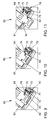
- FIG. 10 shows a section of a cutaway view of the embodiment of the key system 60 according to FIG. 9 in a position between the first locking position and a second locking position, FIG.
- FIG. 11 shows a corresponding section of a cutaway view of the embodiment of the key system 60 in the second locking position.
- the force of the spring 75 can be overcome and the locking pin 74 can be pulled out of the notch 64.
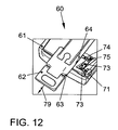
- the emergency key 62 can be pulled out of the housing 61 in the direction of the arrow 79, as shown in FIG. 12.
- Fig. 12 shows a corresponding section of a cutaway view of the key system 60 after release of the second locking position.
- FIG. 13 shows an exemplary embodiment of a key system 90 for a motor vehicle with a so-called crack-frog mechanism in a second arresting position in a cut-open three-dimensional representation.
- the key system 90 has a transmission electronics arranged in a housing 91 for the contactless locking and / or unlocking of a door of the motor vehicle and / or operation of the motor vehicle as well as an emergency key 92 arranged in an interior 93 of the housing 91 for mechanically locking and / or locking Unlocking the door of the motor vehicle and / or the operation of the motor vehicle.
- the housing 91 has a so-called snap-fly mechanism forming elastic element 95 with a pressure point 96.
- the elastic element 95 is also shown in FIG. 14 in a three-dimensional view from below.
- the elastic element 95 is shown separately from the housing 91 in FIG. 13 for reasons of clarity. However, the elastic element 95 is arranged in the mounted state in the area designated by reference numeral 101, which it comprises with outer terminals 97, 98. The elastic element 95 also has latching hooks 99, 100, by means of which the emergency key 92 is locked in the housing 91. For this purpose, the emergency key 92 on its underside corresponding, not visible in Fig. 13 notches.
- the emergency key 92 is completely inserted into the interior 93 of the housing 91 and can be locked by means of the elastic element 95 in this first locking position.
- the emergency key 92 is pressed out of the housing 91 by a resilient element 94, which in the present embodiment is designed as a spiral spring. If the pressure point 96 is relieved, the emergency key 92 can be locked in the second locking position shown in Fig. 13. For this purpose, the emergency key 92 on its underside corresponding, not visible in Fig. 13, further notches. If pressure is exerted again on the pressure point 96, the catch hooks 99, 100 are pressed down again and release the emergency key 92. In this state, the emergency key 92 can be pulled out of the housing 91.
- a resilient element corresponding to the resilient element 94 can also be arranged in the housings 2 and 61, respectively.
- Fig. 15 shows a further embodiment of a key system 110 in a second locking position in three-dimensional representation.
- the key system 110 has a transmission electronics arranged in a housing 111 for the contactless locking and / or unlocking of a door of the motor vehicle and / or operation of the motor vehicle and an emergency key 112 arranged in an interior of the housing 111 for mechanically locking and / or unlocking the door of the motor vehicle and / or the operation of the motor vehicle.
- the housing also has a push button 114.
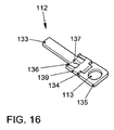
- the emergency key 112 is shown separately in FIG.
- the emergency key 112 has a closing body 136 and a receiving body 135 suitable for receiving a key ring with a circular opening 113.
- the closing body 136 has a closing piece 133 for mechanically locking and / or unlocking the door of the motor vehicle and / or for operating the motor vehicle and a holding body 139 to which the closing piece 133 is fastened.
- the closing body 136 and the receiving body 135 are tiltably connected to one another by means of a hinge 134.
- the closing body 136 also has a notch 137.
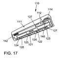
- FIG. 17 shows a cross section of the key system 110 according to FIG. 15 in a first locking position in a three-dimensional representation.
- the key system 110 has four buttons 120, 121, 122 and 123, below which buttons 124, 125, 126 and 127 are arranged.
- buttons 124, 125, 126 and 127 are arranged.
- the button 127 the doors of the motor vehicle can be unlocked.
- buttons 126, a trunk of the motor vehicle can be unlocked and opened.
- the button 125 the doors and the trunk of the motor vehicle can be locked.
- the button 124 the motor vehicle can be started.
- the push button 114 is connected to a detent 140.
- the detent 140 engages in the opening 113 of the emergency key 112 and locks it. If the push button 114 is depressed, then the detent 140 is pressed downwards and out of the opening 113 and thus releases the emergency key 112. In this state, the emergency key 112 is pressed out of the housing 111 by a resilient member 142, which is formed in the present embodiment as a spiral spring. If the push button 114 relieved, the detent 140 can engage in the notch 137 and lock the emergency key 112 in the second locking position shown in Fig. 13.
- the detent 140 is pressed down and out of the notch 137 and thus releases the emergency key 112. In this state, the emergency key 112 can be pulled out of the housing 111 in the direction of the arrow 143.
Landscapes
- Engineering & Computer Science (AREA)
- Mechanical Engineering (AREA)
- Manufacturing & Machinery (AREA)
- Physics & Mathematics (AREA)
- General Physics & Mathematics (AREA)
- Lock And Its Accessories (AREA)
- Automatic Cycles, And Cycles In General (AREA)
- Control Of Throttle Valves Provided In The Intake System Or In The Exhaust System (AREA)
Description
- Die Erfindung betrifft ein Schlüsselsystem für ein Kraftfahrzeug mit einer in einem Gehäuse angeordneten Sendeelektronik zum berührungslosen Ver- und/oder Entriegeln einer Tür des Kraftfahrzeuges und/oder zum Betrieb des Kraftfahrzeuges sowie mit einem Notschlüssel zum mechanisch erfolgenden Ver- und/oder Entriegeln der Tür des Kraftfahrzeuges und/oder zum Betrieb des Kraftfahrzeuges.
- Derartige Schlüsselsysteme sind zum Beispiel aus Dokument DE-A-4444913 bekannt.
- Es ist Aufgabe der Erfindung, ein derartiges Schlüsselsystem zu verbessern.
- Vorgenannte Aufgabe wird durch ein Schlüsselsystem für ein Kraftfahrzeug mit einer in einem Gehäuse angeordneten Sendeelektronik zum berührungslosen Ver- und/oder Entriegeln einer Tür des Kraftfahrzeuges und/oder zum Betrieb des Kraftfahrzeuges sowie einem Notschlüssel zum mechanisch erfolgenden Ver- und/oder Entriegeln der Tür des Kraftfahrzeuges und/oder zum Betrieb des Kraftfahrzeuges gelöst, wobei der Notschlüssel zumindest eine erste Einkerbung, mittels der der Notschlüssel in einer ersten Rastposition in dem Gehäuse arretierbar ist, und eine zweite Einkerbung aufweist, mittels der der Notschlüssel in einer von der ersten Rastposition verschiedenen zweiten Rastposition in dem Gehäuse arretierbar ist, wobei das Gehäuse einen sowohl mit der ersten Einkerbung als auch mit der zweiten Einkerbung des Notschlüssels zusammenwirkenden Rastmechanismus zum Arretieren des Notschlüssels in der ersten und in der zweiten Rastposition aufweist.
- Statt einer Einkerbung sind auch andere mechanisch gleichwirkende Geometrien, wie etwa Ausbuchtungen, möglich, die als Einkerbungen im Sinne der Erfindung verstanden werden können. Durch eine Einkerbung wird ein Gegenpart zu dem Rastmechanismus erzielt, der gegenüber einer Ausbuchtung einen geringeren Aufwand beim mechanischen Arretieren des Notschlüssels erfordert. In einer vorteilhaften Ausgestaltung kann vorgesehen sein, dass eine Öffnung zum Einfädeln eines Schlüsselringes durch einen Rastmechanismus als Einkerbung zum Arretieren des Notschlüssels, insbesondere in der ersten Rastposition, nutzbar ist.
- Kraftfahrzeug im Sinne der Erfindung ist insbesondere ein individuell im Straßenverkehr benutzbares Landfahrzeug. Kraftfahrzeuge im Sinne der Erfindung sind insbesondere nicht auf Landfahrzeuge mit Verbrennungsmotor beschränkt. Eine Tür (eines Kraftfahrzeuges) im Sinne der Erfindung kann insbesondere eine Tür, eine Heck- oder Frontklappe oder ein Kofferraumdeckel sein. Ein zum mechanisch erfolgenden Betrieb des Kraftfahrzeuges ausgebildeter Notschlüssel in Sinne der Erfindung entspricht insbesondere einem mechanischen Schlüssel.
- In vorteilhafter Ausgestaltung der Erfindung weist der Rastmechanismus eine Arretierkugel auf, die zum Arretieren des Notschlüssels in der ersten Rastposition, insbesondere mittels einer Feder, in die erste Einkerbung drückbar ist. In weiterhin vorteilhafter Ausgestaltung der Erfindung ist die Arretierkugel zum Arretieren des Notschlüssels in der zweiten Rastposition, insbesondere mittels einer Feder, in die zweite Einkerbung drückbar.
- In weiterhin vorteilhafter Ausgestaltung der Erfindung weist der Rastmechanismus einen Arretierstift auf, der zum Arretieren des Notschlüssels in der ersten Rastposition, insbesondere mittels einer Feder, in die erste Einkerbung drückbar ist. Der Arretierstift ist in weiterhin vorteilhafter Ausgestaltung der Erfindung zum Arretieren des Notschlüssels in der zweiten Rastposition, insbesondere mittels einer Feder, in die zweite Einkerbung drückbar.
- In weiterhin vorteilhafter Ausgestaltung der Erfindung weist der Rastmechanismus einen Rasthaken auf, der zum Arretieren des Notschlüssels in der ersten Rastposition, insbesondere mittels eines elastischen Elementes, wie z.B. eines sogenannten ,Knackfrosches', in die erste Einkerbung drückbar ist. In weiterhin vorteilhafter Ausgestaltung der Erfindung ist der Rasthaken zum Arretieren des Notschlüssels in der zweiten Rastposition, insbesondere mittels des elastischen Elementes, in die zweite Einkerbung drückbar. In weiterhin vorteilhafter Ausgestaltung der Erfindung ist der Rasthaken durch Druck auf das elastische Element aus der ersten Einkerbung und durch Druck auf das elastische Element aus der zweiten Einkerbung drückbar.
- In weiterhin vorteilhafter Ausgestaltung der Erfindung weist der Rastmechanismus eine Rastung auf, die zum Arretieren des Notschlüssels in der ersten Rastposition in die erste Einkerbung drückbar ist, wobei die erste Einkerbung als Öffnung zur Aufnahme eines Schlüsselringes ausgestaltet ist. In weiterhin vorteilhafter Ausgestaltung der Erfindung ist die Rastung zum Arretieren des Notschlüssels in der zweiten Rastposition in die zweite Einkerbung drückbar.
- In weiterhin vorteilhafter Ausgestaltung der Erfindung weist das Schlüsselsystem zumindest ein federndes Element, insbesondere eine Spiralfeder oder ein Kunststoffstück, auf, mittels dem der Notschlüssel zumindest z.T. aus dem Gehäuse schiebbar ist, wenn sich der Rastmechanismus in einer gelösten Stellung befindet. In einer Ausbildung als Kunststoffstück kann das federnde Element im wesentlichen aus Kunststoff, z.B. Silikon, bestehen. Das federnde Element ist vorteilhafterweise in dem Gehäuse angeordnet.
- In weiterhin vorteilhafter Ausgestaltung der Erfindung ist der Notschlüssel mittels des federnden Elementes von der ersten Rastposition in die zweite Rastposition schiebbar, wenn sich der Rastmechanismus in einer gelösten Stellung befindet, wobei das federnde Element in weiterhin vorteilhafter Ausgestaltung der Erfindung durch Einschieben des Notschlüssels in das Gehäuse spannbar ist.
- Das Gehäuse hat vorteilhafterweise eine Bauhöhe von weniger als 20mm, insbesondere von weniger als 18mm. Es kann vorgesehen sein, dass zudem die Bauhöhe an einer Stirnseite des Gehäuses um in etwa 5mm geringer ist als die Bauhöhe der gegenüberliegenden Stirnseite des Gehäuses.
- Vorgenannte Aufgabe wird zudem - insbesondere in Verbindung mit vorgenannten vorteilhaften Ausgestaltungen - durch ein Schlüsselsystem für ein Kraftfahrzeug mit einer in einem Gehäuse angeordneten Sendeelektronik zum berührungslosen Ver- und/oder Entriegeln einer Tür des Kraftfahrzeuges und/oder zum Betrieb des Kraftfahrzeuges sowie mit einem Notschlüssel zum mechanisch erfolgenden Ver- und/oder Entriegeln der Tür des Kraftfahrzeuges und/oder zum Betrieb des Kraftfahrzeuges gelöst, wobei das Gehäuse einen Rastmechanismus zum Arretieren des Notschlüssels in einer ersten Rastposition und in einer von der ersten Rastposition verschiedenen zweiten Rastposition sowie ein federndes Element aufweist, mittels dessen der Notschlüssel von der ersten Rastposition in die zweite Rastposition schiebbar ist, wenn sich der Rastmechanismus in einer gelösten Stellung befindet.
- Weitere Vorteile und Einzelheiten ergeben sich aus der nachfolgenden Beschreibung von Ausführungsbeispielen. Dabei zeigen:
- Fig. 1
- ein Ausführungsbeispiel eines Schlüsselsystems in einer ersten Arretierposition in dreidimensionaler Darstellung,
- Fig. 2
- ein Ausführungsbeispiel eines Notschlüssels,
- Fig. 3
- ein weiteres Ausführungsbeispiel eines Notschlüssels,
- Fig. 4
- das Ausführungsbeispiel des Schlüsselsystems gemäß Fig. 1 in aufgeschnittener dreidimensionaler Darstellung,
- Fig. 5
- das Ausführungsbeispiel des Schlüsselsystems gemäß Fig. 1 in einer zweiten Arretierposition in dreidimensionaler Darstellung von unten gesehen,
- Fig. 6
- einen Ausschnitt einer aufgeschnittenen Darstellung des Ausführungsbeispiels des Schlüsselsystems gemäß Fig. 1 in der ersten Arretierposition,
- Fig. 7
- einen Ausschnitt einer aufgeschnittenen Darstellung des Ausführungsbeispiels des Schlüsselsystems gemäß Fig. 1 in einer Position zwischen der ersten Arretierposition und der zweiten Arretierposition,
- Fig. 8
- einen Ausschnitt einer aufgeschnittenen Darstellung des Ausführungsbeispiels des Schlüsselsystems gemäß Fig. 1 in der zweiten Arretierposition,
- Fig. 9
- einen Ausschnitt einer aufgeschnittenen Darstellung eines weiteren Ausführungsbeispiels eines Schlüsselsystems in einer ersten Arretierposition,
- Fig. 10
- einen Ausschnitt einer aufgeschnittenen Darstellung des Ausführungsbeispiels des Schlüsselsystems gemäß Fig. 9 in einer Position zwischen der ersten Arretierposition und einer zweiten Arretierposition,
- Fig. 11
- einen Ausschnitt einer aufgeschnittenen Darstellung des Ausführungsbeispiels des Schlüsselsystems gemäß Fig. 9 in der zweiten Arretierposition,
- Fig. 12
- einen Ausschnitt einer aufgeschnittenen Darstellung des Ausführungsbeispiels des Schlüsselsystems gemäß Fig. 9 nach Lösen der zweiten Arretierposition,
- Fig. 13
- ein Ausführungsbeispiel eines Schlüsselsystems mit Knackfrosch-Mechanik in aufgeschnittener dreidimensionaler Darstellung,
- Fig. 14
- ein elastisches Element in dreidimensionaler Darstellung von unten betrachtet,
- Fig. 15
- ein weiteres Ausführungsbeispiel eines Schlüsselsystems in einer zweiten Arretierposition in dreidimensionaler Darstellung,
- Fig. 16
- einen Notschlüssel des Schlüsselsystems gemäß Fig. 15,
- Fig. 17
- einen Querschnitt des Ausführungsbeispiels des Schlüsselsystems gemäß Fig. 15 in einer ersten Arretierposition in dreidimensionaler Darstellung,
- Fig. 1 zeigt ein Ausführungsbeispiel für ein sich in einer ersten Arretierposition befindendes Schlüsselsystem 1 für ein Kraftfahrzeug. Das Schlüsselsystem 1 weist eine in einem Gehäuse 2 angeordnete Sendeelektronik zum berührungslosen Ver- und/oder Entriegeln einer Tür des Kraftfahrzeuges und/oder zum Betrieb des Kraftfahrzeuges sowie einen Notschlüssel 3 zum mechanisch erfolgenden Ver- und/oder Entriegeln der Tür des Kraftfahrzeuges und/oder zum Betrieb des Kraftfahrzeuges auf. Seitlich am Gehäuse 2 ist zudem ein Schubelement 4 vorgesehen.
- Fig. 2 zeigt den Notschlüssel 3 in dreidimensionaler Darstellung. Der Notschlüssel 3 weist einen Schließkörper 6 und einen zur Aufnahme eines Schlüsselringes geeigneten Aufnahmekörper 5 mit einer ovalen Öffnung 11 auf. Der Schließkörper 6 weist ein Schließstück 10 zum mechanisch erfolgenden Ver- und/oder Entriegeln der Tür des Kraftfahrzeuges und/oder zum Betrieb des Kraftfahrzeuges und einen Haltekörper 9 auf, an dem das Schließstück 10 befestigt ist. Der Schließkörper 6 und der Aufnahmekörper 5 sind mittels eines Scharniers 12 kippbar miteinander verbunden. Der Schließkörper 6 weist zudem eine erste Einkerbung 7 und eine zweite Einkerbung 8 auf.
- Fig. 3 zeigt ein zum Notschlüssel 3 alternatives Ausführungsbeispiel eines Notschlüssels 20 in dreidimensionaler Darstellung. Der Notschlüssel 20 weist einen Schließkörper 26 und einen zur Aufnahme eines Schlüsselringes geeigneten Aufnahmekörper 25 mit einer im Gegensatz zur Öffnung 11 kreisrunden Öffnung 21 auf. Der Schließkörper 26 weist ein Schließstück 23 zum mechanisch erfolgenden Ver- und/oder Entriegeln der Tür des Kraftfahrzeuges und/oder zum Betrieb des Kraftfahrzeuges und einen Haltekörper 29 auf, an dem das Schließstück 23 befestigt ist. Der Schließkörper 26 und der Aufnahmekörper 25 sind mittels eines Scharniers 22 kippbar miteinander verbunden. Der Schließkörper 26 weist zudem eine erste Einkerbung 27 und eine zweite Einkerbung 28 auf. Fig. 2 und Fig. 3 zeigen zudem beispielhafte Maßangaben in mm.
- Fig. 4 zeigt das Ausführungsbeispiel des Schlüsselsystems 1 gemäß Fig. 1 in aufgeschnittener dreidimensionaler Darstellung. Der Notschlüssel 3 ist vollständig in einem Innenraum 30 des Gehäuses 2 aufgenommen.
- Fig. 5 zeigt das Ausführungsbeispiel des Schlüsselsystems 1 gemäß Fig. 1 in einer zweiten Arretierposition in dreidimensionaler Darstellung von unten gesehen. In der zweiten Arretierposition ist der Schließkörper 6 vollständig in einem Innenraum 30 des Gehäuses 3 untergebracht. Der Aufnahmekörper 5 mit der ovalen Öffnung 11 befindet sich dagegen außerhalb des Gehäuses 2. In der beispielhaften Ausgestaltung befindet sich der Aufnahmekörper 5 gerade soweit außerhalb des Gehäuses 2, dass der Ausnahmekörper 5 kippbar ist.
- Das Schlüsselsystem 1 weist einen mäanderförmigen Schaltbereich 40 mit vier Schaltflächen 41, 42, 43 und 44 auf. Mittels der Schaltfläche 41 sind die Türen des Kraftfahrzeuges entriegelbar. Mittels der Schaltfläche 42 ist ein Kofferraum des Kraftfahrzeuges entriegelbar und zu öffnen. Mittels der Schaltfläche 43 sind die Türen und der Kofferraum des Kraftfahrzeuges verriegelbar. Mittels der Schaltfläche 44 kann das Kraftfahrzeug gestartet werden.
- Fig. 6 zeigt einen Ausschnitt einer aufgeschnittenen Darstellung des Ausführungsbeispiels des Schlüsselsystems 1 gemäß Fig. 1 in der ersten Arretierposition. Der in Fig. 6 dargestellte Ausschnitt des Schlüsselsystems 1 zeigt einen mit der Einkerbung 7 des Notschlüssels zusammenwirkenden Rastmechanismus zum Arretieren des Notschlüssels 3 in der ersten Arretierposition. Der Rastmechanismus weist einen mit dem Schubelement 4 verbundenen Arretierkörper 50 mit einer Aussparung 57, eine Arretierkugel 51 und eine Arretierfeder 52 auf. Mittels des Arretierkörpers 50 wird die Arretierkugel 51 in die Einkerbung 7 gedrückt, so dass der Notschlüssel 22 in der ersten Arretierposition fixiert ist. Die Arretierfeder 52 hält den Arretierkörper 50 dabei in dieser Position.
- Durch Schieben des Schubelementes 4 in Richtung des Pfeils 54 gerät die Arretierkugel 51 in die Aussparung 57, so dass die Arretierung durch das Zusammenwirken von Arretierkugel 51 und Einkerbung 7 aufgehoben wird. Durch ein nicht dargestelltes federndes Element wird der Notschlüssel 3 z.T. aus dem Gehäuse gedrückt wie dies in Fig. 7 dargestellt ist. Fig. 7 zeigt dabei einen Ausschnitt einer aufgeschnittenen Darstellung des Schlüsselsystems 1 in einer Position zwischen der ersten Arretierposition und der zweiten Arretierposition.
- Wird das Schubelement 4 losgelassen, so drückt die Arretierfeder 52 den Arretierkörper 50 zurück in die Ausgangsposition, so dass der Arretierkörper 50 die Arretierkugel 51 in die Einkerbung 8 drückt. Auf diese Weise wird der Notschlüssel 3 - wie in Fig. 8 gezeigt - im Gehäuse 2 in der zweiten Arretierposition arretiert. Durch erneutes Schieben des Schubelementes 4 in Richtung des Pfeils 54 gerät die Arretierkugel 51 erneut in die Aussparung 57, so dass die Arretierung durch das Zusammenwirken von Arretierkugel 51 und Einkerbung 8 aufgehoben wird. In diesem Zustand kann der Notschlüssel 3 aus dem Gehäuse gezogen werden.
- Fig. 9 zeigt einen Ausschnitt einer aufgeschnittenen Darstellung eines weiteren Ausführungsbeispiels eines Schlüsselsystems 60 in einer ersten Arretierposition. Das Schlüsselsystem 60 weist ein Gehäuse 61 auf, in das ein Notschlüssel 62 vollständig hineingeschoben ist. Der Notschlüssel 62 entspricht dem Notschlüssel 3, weist jedoch zwei von den Einkerbungen 7 und 8 verschieden gestaltete Einkerbungen 63 und 64 auf. Das Gehäuse 61 entspricht dem Gehäuse 2, unterscheidet sich jedoch durch seinen Rastmechanismus. Der Rastmechanismus des Gehäuses 61 weist einen Druckstift 71, einen um einen Stift 72 schwenkbaren Arretierhebel 73, einen Arretierstift 74 und eine Feder 75 auf. Der Arretierhebel 73 weist zwei Enden auf, wobei an einem Ende der Druckstift 71 und an dem anderen Ende der Arretierstift 74 beweglich befestigt ist.
- Mittels der Feder 75 wird der Arretierstift 74 in die Einkerbung 63 bedrückt, so dass der Notschlüssel 62 in der ersten Arretierposition arretiert ist. Durch Drücken des Druckstiftes 71, wie dies durch den Pfeil 70 angedeutet ist, kann die Kraft der Feder 75 überwunden und der Arretierstift 74 aus der Einkerbung 63 gezogen werden. Durch ein nicht dargestelltes federndes Element wird der Notschlüssel 62 z.T. aus dem Gehäuse gedrückt, wie dies in Fig. 10 dargestellt ist. Fig. 10 zeigt dabei einen Ausschnitt einer aufgeschnittenen Darstellung des Ausführungsbeispiels des Schlüsselsystems 60 gemäß Fig. 9 in einer Position zwischen der ersten Arretierposition und einer zweiten Arretierposition,
- Wird der Druckstift 71 losgelassen, so drückt die Feder 75 den Arretierstift 74 in die Einkerbung 64 und arretiert den Notschlüssel 62 in der zweiten Arretierposition. Fig. 11 zeigt einen entsprechenden Ausschnitt einer aufgeschnittenen Darstellung des Ausführungsbeispiels des Schlüsselsystems 60 in der zweiten Arretierposition. Durch erneutes Drücken des Druckstiftes 71, wie dies durch den Pfeil 78 angedeutet ist, kann die Kraft der Feder 75 überwunden und der Arretierstift 74 aus der Einkerbung 64 gezogen werden. In diesen Zustand kann der Notschlüssel 62 - wie in Fig. 12 gezeigt - in Richtung des Pfeils 79 aus dem Gehäuse 61 gezogen werden. Fig. 12 zeigt entsprechend einen Ausschnitt einer aufgeschnittenen Darstellung des Schlüsselsystems 60 nach Lösen der zweiten Arretierposition.
- Fig. 13 zeigt ein Ausführungsbeispiel eines Schlüsselsystems 90 für ein Kraftfahrzeug mit einer sogenannten Knackfrosch-Mechanik in einer zweiten Arretierposition in aufgeschnittener dreidimensionaler Darstellung. Das Schlüsselsystem 90 weist eine in einem Gehäuse 91 angeordnete Sendeelektronik zum berührungslosen Ver- und/oder Entriegeln einer Tür des Kraftfahrzeuges und/oder zum Betrieb des Kraftfahrzeuges sowie einen in einem Innenraum 93 des Gehäuses 91 angeordneten Notschlüssel 92 zum mechanisch erfolgenden Ver- und/oder Entriegeln der Tür des Kraftfahrzeuges und/oder zum Betrieb des Kraftfahrzeuges auf.
- Das Gehäuse 91 weist ein die sogenannte Knackfrosch-Mechanik bildendes elastisches Element 95 mit einem Druckpunkt 96 auf. Das elastische Element 95 ist in Fig. 14 zudem in dreidimensionaler Darstellung von unten betrachtet dargestellt.
- Das elastische Element 95 ist in Fig. 13 aus Gründen der Übersichtlichkeit vom Gehäuse 91 getrennt dargestellt. Das elastische Element 95 ist im montierten Zustand jedoch in dem mit Bezugszeichen 101 bezeichneten Bereich angeordnet, den es mit äußeren Klemmen 97, 98 umfasst. Das elastische Element 95 weist zudem Rasthaken 99, 100 auf, mittels derer der Notschlüssel 92 im Gehäuse 91 arretiert wird. Dazu weist der Notschlüssel 92 an seiner Unterseite entsprechende, in Fig. 13 nicht erkennbare Einkerbungen auf.
- Der Notschlüssel 92 ist vollständig in den Innenraum 93 des Gehäuses 91 einschiebbar und mittels des elastischen Elementes 95 in dieser ersten Arretierposition arretierbar.
- Wird Druck auf den Druckpunkt 96 angeübt, so werden die Rasthaken 99, 100 nach unten gedrückt und geben den Notschlüssel 92 frei. In diesem Zustand wird der Notschlüssel 92 durch ein federndes Element 94, das im vorliegenden Ausführungsbeispiel als Spiralfeder ausgebildet ist, aus dem Gehäuse 91 gedrückt. Wird der Druckpunkt 96 entlastet, kann der Notschlüssel 92 in der in Fig. 13 dargestellten zweiten Arretierposition arretiert werden. Dazu weist der Notschlüssel 92 an seiner Unterseite entsprechende, in Fig. 13 nicht erkennbare, weitere Einkerbungen auf. Wird erneut Druck auf den Druckpunkt 96 angeübt, so werden die Rasthaken 99, 100 wiederum nach unten gedrückt und geben den Notschlüssel 92 frei. In diesem Zustand kann der Notschlüssel 92 aus dem Gehäuse 91 gezogen werden.
- Ein dem federnden Element 94 entsprechendes federndes Element kann auch in den Gehäusen 2 bzw. 61 angeordnet werden.
- Fig. 15 zeigt ein weiteres Ausführungsbeispiel eines Schlüsselsystems 110 in einer zweiten Arretierposition in dreidimensionaler Darstellung. Das Schlüsselsystem 110 weist eine in einem Gehäuse 111 angeordnete Sendeelektronik zum berührungslosen Ver- und/oder Entriegeln einer Tür des Kraftfahrzeuges und/oder zum Betrieb des Kraftfahrzeuges sowie einen in einem Innenraum des Gehäuses 111 angeordneten Notschlüssel 112 zum mechanisch erfolgenden Ver- und/oder Entriegeln der Tür des Kraftfahrzeuges und/oder zum Betrieb des Kraftfahrzeuges auf. Das Gehäuse weist zudem eine Drucktaste 114 auf.
- Der Notschlüssel 112 ist separat in Fig. 16 dargestellt. Der Notschlüssel 112 weist einen Schließkörper 136 und einen zur Aufnahme eines Schlüsselringes geeigneten Aufnahmekörper 135 mit einer kreisrunden Öffnung 113 auf. Der Schließkörper 136 weist ein Schließstück 133 zum mechanisch erfolgenden Ver- und/oder Entriegeln der Tür des Kraftfahrzeuges und/oder zum Betrieb des Kraftfahrzeuges und einen Haltekörper 139 auf, an dem das Schließstück 133 befestigt ist. Der Schließkörper 136 und der Aufnahmekörper 135 sind mittels eines Scharniers 134 kippbar miteinander verbunden. Der Schließkörper 136 weist zudem eine Einkerbung 137 auf.
- Fig. 17 zeigt einen Querschnitt des Schlüsselsystems 110 gemäß Fig. 15 in einer ersten Arretierposition in dreidimensionaler Darstellung. Das Schlüsselsystem 110 weist vier Schaltflächen 120, 121, 122 und 123 auf, unter denen Taster 124, 125, 126 und 127 angeordnet sind. Mittels des Tasters 127 sind die Türen des Kraftfahrzeuges entriegelbar. Mittels des Tasters 126 ist ein Kofferraum des Kraftfahrzeuges entriegelbar und zu öffnen. Mittels des Tasters 125 sind die Türen und der Kofferraum des Kraftfahrzeuges verriegelbar. Mittels des Tasters 124 kann das Kraftfahrzeug gestartet werden.
- Die Drucktaste 114 ist mit einer Rastung 140 verbunden. In der in Fig. 15 dargestellten ersten Arretierposition rastet die Rastung 140 in der Öffnung 113 des Notschlüssel 112 und arretiert diesen. Wird die Drucktaste 114 heruntergedrückt, so wird auch die Rastung 140 nach unten und aus der Öffnung 113 gedrückt und gibt damit den Notschlüssel 112 frei. In diesem Zustand wird der Notschlüssel 112 durch ein federndes Element 142, das im vorliegenden Ausführungsbeispiel als Spiralfeder ausgebildet ist, aus den Gehäuse 111 gedrückt. Wird die Drucktaste 114 entlastet, kann die Rastung 140 in die Einkerbung 137 einrasten und den Notschlüssel 112 in der in Fig. 13 dargestellten zweiten Arretierposition arretieren.
- Wird die Drucktaste 114 erneut heruntergedrückt, so wird auch die Rastung 140 nach unten und aus der Einkerbung 137 gedrückt und gibt damit den Notschlüssel 112 frei. In diesem Zustand kann der Notschlüssel 112 in Richtung des Pfeils 143 aus dem Gehäuse 111 gezogen werden.
-
- 1, 60, 90, 110
- Schlüsselsystem
- 2, 61, 91,111
- Gehäuse
- 3, 20, 62, 92, 112
- Notschlüssel
- 4
- Schubelement
- 5, 25, 135
- Aufnahmekörper
- 6, 26, 136
- Schließkörper
- 7, 8, 27, 28, 63, 64, 137
- Einkerbung
- 9, 29, 139
- Haltekörper
- 10, 23, 133
- Schließstück
- 11,21,113
- Öffnung
- 12, 22,134
- Scharnier
- 30, 93
- Innenraum
- 40
- mäanderförmiger Schaltbereich
- 41,42,43,44,120, 121, 122, 123
- Schaltfläche
- 50
- Arretierkörper
- 51
- Arretierkugel
- 52
- Arretierfeder
- 54, 70, 78, 79, 143
- Pfeil
- 57
- Aussparung
- 71 _
- Druckstift
- 72
- Stift
- 73
- Arretierhebel
- 74
- Arretierstift
- 75
- Feder
- 94, 142
- federndes Element
- 95
- elastisches Element
- 96
- Druckpunkt
- 97, 98
- äußere Klemmen
- 99, 100
- Rasthaken
- 101
- Bereich
- 114
- Drucktaste
- 124, 125, 126, 127
- Taster
- 140
- Rastung
Claims (19)
- Schlüsselsystem (1, 60, 90, 110) für ein Kraftfahrzeug mit einer in einem Gehäuse (2, 61, 91, 111) angeordneten Sendeelektronik zum berührungslosen Ver- und/oder Entriegeln einer Tür des Kraftfahrzeuges und/oder zum Betrieb des Kraftfahrzeuges sowie mit einem Notschlüssel (3, 20, 62, 92, 112) zum mechanisch erfolgenden Ver- und/oder Entriegeln der Tür des Kraftfahrzeuges und/oder zum Betrieb des Kraftfahrzeuges, dadurch gekennzeichnet, dass der Notschlüssel (3, 20, 62, 92, 112) zumindest eine erste Einkerbung (7, 27, 63, 113) aufweist, mittels der der Notschlüssel (3, 20, 62, 92, 112) in einer ersten Rastposition in dem Gehäuse (2, 61, 91, 111) arretierbar ist, und eine zweite Einkerbung (8, 28, 64, 137) aufweist, mittels der der Notschlüssel (3, 20, 62, 92, 112) in einer von der ersten Rastposition verschiedenen zweiten Rastposition in dem Gehäuse (2, 61, 91, 111) arretierbar ist, wobei das Gehäuse (2, 61, 91, 111) einen sowohl mit der ersten Einkerbung (7, 27, 63, 113) als auch mit der zweiten Einkerbung (8, 28, 64, 137) des Notschlüssels (3, 20, 62, 92, 112) zusammenwirkenden Rastmechanismus zum Arretieren des Notschlüssels (3, 20, 62, 92, 112) in der ersten und in der zweiten Rastposition aufweist.
- Schlüsselsystem (1, 60, 90, 110) nach Anspruch 1, dadurch gekennzeichnet, dass der Rastmechanismus eine Arretierkugel (51) aufweist, die zum Arretieren des Notschlüssels (3) in der ersten Rastposition in die erste Einkerbung (7) drückbar ist.
- Schlüsselsystem (1, 60, 90, 110) nach Anspruch 2, dadurch gekennzeichnet, dass die Arretierkugel (51) zum Arretieren des Notschlüssels (3) in der zweiten Rastposition in die zweite Einkerbung (8) drückbar ist.
- Schlüsselsystem (1, 60, 90, 110) nach Anspruch 1, dadurch gekennzeichnet, dass der Rastmechanismus einen Arretierstift (74) aufweist, der zum Arretieren des Notschlüssels (62) in der ersten Rastposition in die erste Einkerbung (63) drückbar ist.
- Schlüsselsystem (1, 60, 90, 110) nach Anspruch 4, dadurch gekennzeichnet, dass der Arretierstift (74) zum Arretieren des Notschlüssels (62) in der zweiten Rastposition in die zweite Einkerbung (64) drückbar ist.
- Schlüsselsystem (1, 60, 90, 110) nach Anspruch 1, dadurch gekennzeichnet, dass der Rastmechanismus einen Rasthaken (99, 100) aufweist, der zum Arretieren des Notschlüssels (62) in der ersten Rastposition in die erste Einkerbung drückbar ist.
- Schlüsselsystem (1, 60, 90, 110) nach Anspruch 6, dadurch gekennzeichnet, dass der Rasthaken (99, 100) zum Arretieren des Notschlüssels (62) in der zweiten Rastposition in die zweite Einkerbung drückbar ist.
- Schlüsselsystem (1, 60, 90, 110) nach Anspruch6 oder 7, dadurch gekennzeichnet, dass der Rastmechanismus ein elastisches Element (95) aufweist.
- Schlüsselsystem (1, 60, 90, 110) nach Anspruch 8, dadurch gekennzeichnet, dass der Rasthaken (99, 100) durch Druck auf das elastische Element (95) aus der ersten Einkerbung drückbar ist
- Schlüsselsystem (1, 60, 90, 110) nach Anspruch 8 oder 9, dadurch gekennzeichnet, dass der Rasthaken (99, 100) durch Druck auf das elastische Element (95) aus der zweiten Einkerbung drückbar ist.
- Schlüsselsystem (1, 60, 90, 110) nach Anspruch 1, dadurch gekennzeichnet, dass der Rastmechanismus eine Rastung (140) aufweist, die zum Arretieren des Notschlüssels (3) in der ersten Rastposition in die erste Einkerbung drückbar ist, wobei die erste Einkerbung als Öffnung (113) zur Aufnahme eines Schlüsselringes ausgestaltet ist.
- Schlüsselsystem (1, 60, 90, 110) nach Anspruch 11, dadurch gekennzeichnet, dass die Rastung (140) zum Arretieren des Notschlüssels (3) in der zweiten Rastposition in die zweite Einkerbung (137) drückbar ist.
- Schlüsselsystem (1, 60, 90, 110) nach einem der vorhergehenden Ansprüche, dadurch gekennzeichnet, dass es zumindest ein federndes Element (94, 142) aufweist, mittels dessen der Notschlüssel (3, 20, 62, 92, 112) zumindest zum Teil aus dem Gehäuse (2, 61, 91, 111) schiebbar ist, wenn sich der Rastmechanismus in einer gelösten Stellung befindet.
- Schlüsselsystem (1, 60, 90, 110) nach Anspruch 13, dadurch gekennzeichnet, dass der Notschlüssel (3, 20, 62, 92, 112) mittels des federnden Elementes (94, 142) von der ersten Rastposition in die zweite Rastposition schiebbar ist, wenn sich der Rastmechanismus in einer gelösten Stellung befindet.
- Schlüsselsystem (1, 60, 90, 110) für ein Kraftfahrzeug mit einer in einem Gehäuse (2, 61, 91, 111) angeordneten Sendeelektronik zum berührungslosen Ver- und/oder Entriegeln einer Tür des Kraftfahrzeuges und/oder zum Betrieb des Kraftfahrzeuges sowie mit einem Notschlüssel (3, 20, 62, 92, 112) zum mechanisch erfolgenden Ver- und/oder Entriegeln der Tür des Kraftfahrzeuges und/oder zum Betrieb des Kraftfahrzeuges, dadurch gekennzeichnet, dass das Gehäuse (2, 61, 91, 111) einen Rastmechanismus zum Arretieren des Notschlüssels (3, 20, 62, 92, 112) in einer ersten Rastposition und in einer von der ersten Rastposition verschiedenen zweiten Rastposition sowie ein federndes Element (94, 142) aufweist, mittels dessen der Notschlüssel (3, 20, 62, 92, 112) von der ersten Rastposition in die zweite Rastposition schiebbar ist, wenn sich der Rastmechanismus in einer gelösten Stellung befindet.
- Schlüsselsystem (1, 60, 90, 110) nach einem der Ansprüche 13 bis 15, dadurch gekennzeichnet, dass das federnde Element (94, 142) eine Spiralfeder ist.
- Schlüsselsystem (1, 60, 90, 110) nach einem der Ansprüche 13 bis 16, dadurch gekennzeichnet, dass das federnde Element (94, 142) Kunststoff aufweist.
- Schlüsselsystem (1, 60, 90, 110) nach einem der Ansprüche 13 bis 17, dadurch gekennzeichnet, dass das federnde Element (94, 142) in dem Gehäuse (2, 61, 91, 111) angeordnet ist.
- Schlüsselsystem (1, 60, 90, 110) nach einem der Ansprüche 13 bis 18, dadurch gekennzeichnet, dass das federnde Element (94, 142) durch Einschieben des Notschlüssels in das Gehäuse (2, 61, 91, 111) spannbar ist.
Applications Claiming Priority (2)
| Application Number | Priority Date | Filing Date | Title |
|---|---|---|---|
| DE10331087 | 2003-07-09 | ||
| DE10331087A DE10331087A1 (de) | 2003-07-09 | 2003-07-09 | Schlüsselsystem für ein Kraftfahrzeug |
Publications (2)
| Publication Number | Publication Date |
|---|---|
| EP1496175A1 EP1496175A1 (de) | 2005-01-12 |
| EP1496175B1 true EP1496175B1 (de) | 2006-08-30 |
Family
ID=33441686
Family Applications (1)
| Application Number | Title | Priority Date | Filing Date |
|---|---|---|---|
| EP04014221A Expired - Lifetime EP1496175B1 (de) | 2003-07-09 | 2004-06-17 | Schlüsselsystem für ein Kraftfahrzeug |
Country Status (3)
| Country | Link |
|---|---|
| EP (1) | EP1496175B1 (de) |
| AT (1) | ATE338179T1 (de) |
| DE (2) | DE10331087A1 (de) |
Families Citing this family (15)
| Publication number | Priority date | Publication date | Assignee | Title |
|---|---|---|---|---|
| DE102004049264A1 (de) * | 2004-10-09 | 2006-04-13 | Conti Temic Microelectronic Gmbh | Fernbedienungseinheit |
| DE102004049263A1 (de) * | 2004-10-09 | 2006-04-13 | Conti Temic Microelectronic Gmbh | Schlüssel |
| EP1750230B1 (de) * | 2005-07-16 | 2015-06-17 | Marquardt GmbH | Gehäuse, insbesondere für einen elektronischen Schlüssel |
| WO2008006551A1 (de) | 2006-07-13 | 2008-01-17 | Volkswagen Aktiengesellschaft | Schlüsseleinheit für ein schlosssystem eines fahrzeugs |
| DE102007014179B4 (de) * | 2007-03-24 | 2020-02-20 | Huf Hülsbeck & Fürst Gmbh & Co. Kg | Elektronischer Schlüssel zur Fernbedienung von Fahrzeugen |
| DE102008005840B4 (de) | 2008-01-24 | 2018-07-19 | HELLA GmbH & Co. KGaA | Elektronischer Schlüssel mit einem mechanischen Notschlüssel |
| FR2927512B1 (fr) * | 2008-02-19 | 2011-04-22 | Peugeot Citroen Automobiles Sa | Boitier de telecommande ou de badge mains libres pour vehicule a element porte-clefs escamotable dans ce boitier. |
| DE102012100162A1 (de) | 2012-01-10 | 2013-07-11 | Huf Hülsbeck & Fürst Gmbh & Co. Kg | Funkschlüssel für ein Kraftfahrzeug |
| US9593514B2 (en) * | 2013-02-18 | 2017-03-14 | Ford Global Technologies, Llc | Seamless exterior handle for a vehicle door |
| DE102014004806A1 (de) * | 2014-04-03 | 2015-10-08 | Huf Hülsbeck & Fürst Gmbh & Co. Kg | Kraftfahrzeugschlüssel mit Notschlüssel |
| IT201600129819A1 (it) * | 2016-12-22 | 2018-06-22 | Giobert Spa | Dispositivo di avviamento per veicolo |
| CN108729745B (zh) * | 2017-04-20 | 2020-05-15 | 上海海拉电子有限公司 | 一种车辆的备用钥匙及放置该备用钥匙的遥控钥匙 |
| DE102019111045A1 (de) * | 2019-04-29 | 2020-10-29 | HELLA GmbH & Co. KGaA | Elektronisches Schlüsselsystem für ein Kraftfahrzeug |
| KR102772332B1 (ko) * | 2019-09-25 | 2025-02-25 | 현대자동차주식회사 | 차량용 키 어셈블리 |
| DE102020200979B3 (de) | 2020-01-28 | 2021-04-22 | Continental Automotive Gmbh | Vorrichtung zum Unterbringen einer Komponente |
Family Cites Families (9)
| Publication number | Priority date | Publication date | Assignee | Title |
|---|---|---|---|---|
| US3328986A (en) * | 1964-06-15 | 1967-07-04 | Ralton Theodore | Mechanical key holder |
| US5440910A (en) * | 1993-06-07 | 1995-08-15 | Florian; David W. | Key adaptor |
| DE4444913C2 (de) * | 1993-12-18 | 1999-12-16 | Marquardt Gmbh | Schlüssel |
| DE19605201B4 (de) * | 1996-02-13 | 2007-04-12 | Marquardt Gmbh | Gehäuse für einen elektronischen Schlüssel |
| DE19820831C1 (de) * | 1998-05-09 | 1999-08-26 | Daimler Chrysler Ag | Schlüssel |
| DE19912749C1 (de) * | 1999-03-22 | 2000-11-02 | Valeo Gmbh & Co Schliessyst Kg | Flachschlüssel |
| DE19964314C2 (de) * | 1999-11-24 | 2003-07-10 | Huf Huelsbeck & Fuerst Gmbh | Schlüssel, insbesondere für Kfz |
| DE19958819C1 (de) * | 1999-12-07 | 2001-05-10 | Valeo Gmbh & Co Schliessyst Kg | Flachschüssel |
| FR2828515B1 (fr) * | 2001-08-08 | 2004-02-27 | Valeo Securite Habitacle | Cle a panneton articule |
-
2003
- 2003-07-09 DE DE10331087A patent/DE10331087A1/de not_active Withdrawn
-
2004
- 2004-06-17 AT AT04014221T patent/ATE338179T1/de not_active IP Right Cessation
- 2004-06-17 DE DE502004001311T patent/DE502004001311D1/de not_active Expired - Lifetime
- 2004-06-17 EP EP04014221A patent/EP1496175B1/de not_active Expired - Lifetime
Also Published As
| Publication number | Publication date |
|---|---|
| EP1496175A1 (de) | 2005-01-12 |
| ATE338179T1 (de) | 2006-09-15 |
| DE10331087A1 (de) | 2005-02-03 |
| DE502004001311D1 (de) | 2006-10-12 |
Similar Documents
| Publication | Publication Date | Title |
|---|---|---|
| DE4421808C2 (de) | Türverriegelungsvorrichtung mit einem Anti-Diebstahls-Mechanismus | |
| DE60110670T2 (de) | Verriegelungsvorrichtung | |
| DE19821754B4 (de) | Verriegelungsvorrichtung für eine Kraftfahrzeugtür | |
| DE102009045843A1 (de) | Griffvorrichtung | |
| DE102008048712A1 (de) | Schlosseinheit mit Mehrklinken-Gesperre | |
| DE102018208950A1 (de) | Verschluss-Verriegelungsanordnung mit Verriegelungsmechanismus und einem äußeren Lösemechanismus mit Rückstellvorrichtung | |
| DE102017207295A1 (de) | Verschlussverriegelung für eine Fahrzeugtür mit Doppelzug-Lösemechanismus, der von einem Kindersicherungs-Betätigungsglied angetrieben wird | |
| DE102015122365A1 (de) | Türgriffanordnung für ein Kraftfahrzeug | |
| DE202008012706U1 (de) | Schlosseinheit mit mehrteiliger Sperrklinke und federvorgespannter Blockierklinke | |
| EP1496175A1 (de) | Schlüsselsystem für ein Kraftfahrzeug | |
| DE112016006079T5 (de) | Fahrzeug-türverriegelungssystem | |
| DE19845723B4 (de) | Verriegelungsvorrichtung für eine Fahrzeugtür | |
| DE102012206577A1 (de) | Tür-Schließvorrichtung | |
| DE102012203734A1 (de) | Schloss für eine Klappe oder Tür | |
| DE202009015561U1 (de) | Kraftfahrzeugtürverschluss | |
| DE10006765B4 (de) | Kraftfahrzeug-Türschloß mit kompaktem Aufbau | |
| DE102007013228A1 (de) | Lenkradschlosseinrichtung | |
| DE202007008652U1 (de) | Kraftfahrzeugschloß | |
| EP2927394B1 (de) | Kraftfahrzeugschlüssel mit Notschlüssel | |
| DE102014112031A1 (de) | Schloss | |
| DE2250173A1 (de) | Schloss fuer sicherheitsgurte | |
| DE102012102485A1 (de) | Handhabe eines Kraftfahrzeuges mit einem bewegbaren Abdeckelement | |
| DE102022120793A1 (de) | Knopfanordnung für ein auslösesystem mit einem zahnstangengetriebe und einem ritzel | |
| EP3179021B1 (de) | Türgriffanordnung für ein kraftfahrzeug | |
| EP1669526B1 (de) | Kraftfahrzeugschloss |
Legal Events
| Date | Code | Title | Description |
|---|---|---|---|
| PUAI | Public reference made under article 153(3) epc to a published international application that has entered the european phase |
Free format text: ORIGINAL CODE: 0009012 |
|
| AK | Designated contracting states |
Kind code of ref document: A1 Designated state(s): AT BE BG CH CY CZ DE DK EE ES FI FR GB GR HU IE IT LI LU MC NL PL PT RO SE SI SK TR |
|
| AX | Request for extension of the european patent |
Extension state: AL HR LT LV MK |
|
| 17P | Request for examination filed |
Effective date: 20050712 |
|
| AKX | Designation fees paid |
Designated state(s): AT BE BG CH CY CZ DE DK EE ES FI FR GB GR HU IE IT LI LU MC NL PL PT RO SE SI SK TR |
|
| GRAP | Despatch of communication of intention to grant a patent |
Free format text: ORIGINAL CODE: EPIDOSNIGR1 |
|
| GRAS | Grant fee paid |
Free format text: ORIGINAL CODE: EPIDOSNIGR3 |
|
| GRAA | (expected) grant |
Free format text: ORIGINAL CODE: 0009210 |
|
| AK | Designated contracting states |
Kind code of ref document: B1 Designated state(s): AT BE BG CH CY CZ DE DK EE ES FI FR GB GR HU IE IT LI LU MC NL PL PT RO SE SI SK TR |
|
| PG25 | Lapsed in a contracting state [announced via postgrant information from national office to epo] |
Ref country code: IT Free format text: LAPSE BECAUSE OF FAILURE TO SUBMIT A TRANSLATION OF THE DESCRIPTION OR TO PAY THE FEE WITHIN THE PRESCRIBED TIME-LIMIT;WARNING: LAPSES OF ITALIAN PATENTS WITH EFFECTIVE DATE BEFORE 2007 MAY HAVE OCCURRED AT ANY TIME BEFORE 2007. THE CORRECT EFFECTIVE DATE MAY BE DIFFERENT FROM THE ONE RECORDED. Effective date: 20060830 Ref country code: GB Free format text: LAPSE BECAUSE OF FAILURE TO SUBMIT A TRANSLATION OF THE DESCRIPTION OR TO PAY THE FEE WITHIN THE PRESCRIBED TIME-LIMIT Effective date: 20060830 Ref country code: SI Free format text: LAPSE BECAUSE OF FAILURE TO SUBMIT A TRANSLATION OF THE DESCRIPTION OR TO PAY THE FEE WITHIN THE PRESCRIBED TIME-LIMIT Effective date: 20060830 Ref country code: RO Free format text: LAPSE BECAUSE OF FAILURE TO SUBMIT A TRANSLATION OF THE DESCRIPTION OR TO PAY THE FEE WITHIN THE PRESCRIBED TIME-LIMIT Effective date: 20060830 Ref country code: SK Free format text: LAPSE BECAUSE OF FAILURE TO SUBMIT A TRANSLATION OF THE DESCRIPTION OR TO PAY THE FEE WITHIN THE PRESCRIBED TIME-LIMIT Effective date: 20060830 Ref country code: PL Free format text: LAPSE BECAUSE OF FAILURE TO SUBMIT A TRANSLATION OF THE DESCRIPTION OR TO PAY THE FEE WITHIN THE PRESCRIBED TIME-LIMIT Effective date: 20060830 Ref country code: NL Free format text: LAPSE BECAUSE OF FAILURE TO SUBMIT A TRANSLATION OF THE DESCRIPTION OR TO PAY THE FEE WITHIN THE PRESCRIBED TIME-LIMIT Effective date: 20060830 Ref country code: IE Free format text: LAPSE BECAUSE OF FAILURE TO SUBMIT A TRANSLATION OF THE DESCRIPTION OR TO PAY THE FEE WITHIN THE PRESCRIBED TIME-LIMIT Effective date: 20060830 Ref country code: FI Free format text: LAPSE BECAUSE OF FAILURE TO SUBMIT A TRANSLATION OF THE DESCRIPTION OR TO PAY THE FEE WITHIN THE PRESCRIBED TIME-LIMIT Effective date: 20060830 Ref country code: CZ Free format text: LAPSE BECAUSE OF FAILURE TO SUBMIT A TRANSLATION OF THE DESCRIPTION OR TO PAY THE FEE WITHIN THE PRESCRIBED TIME-LIMIT Effective date: 20060830 |
|
| REG | Reference to a national code |
Ref country code: GB Ref legal event code: FG4D Free format text: NOT ENGLISH |
|
| REG | Reference to a national code |
Ref country code: CH Ref legal event code: EP |
|
| REG | Reference to a national code |
Ref country code: IE Ref legal event code: FG4D Free format text: LANGUAGE OF EP DOCUMENT: GERMAN |
|
| REF | Corresponds to: |
Ref document number: 502004001311 Country of ref document: DE Date of ref document: 20061012 Kind code of ref document: P |
|
| REG | Reference to a national code |
Ref country code: DE Ref legal event code: R096 Ref document number: 502004001311 Country of ref document: DE Effective date: 20061012 |
|
| PG25 | Lapsed in a contracting state [announced via postgrant information from national office to epo] |
Ref country code: SE Free format text: LAPSE BECAUSE OF FAILURE TO SUBMIT A TRANSLATION OF THE DESCRIPTION OR TO PAY THE FEE WITHIN THE PRESCRIBED TIME-LIMIT Effective date: 20061130 Ref country code: BG Free format text: LAPSE BECAUSE OF FAILURE TO SUBMIT A TRANSLATION OF THE DESCRIPTION OR TO PAY THE FEE WITHIN THE PRESCRIBED TIME-LIMIT Effective date: 20061130 Ref country code: DK Free format text: LAPSE BECAUSE OF FAILURE TO SUBMIT A TRANSLATION OF THE DESCRIPTION OR TO PAY THE FEE WITHIN THE PRESCRIBED TIME-LIMIT Effective date: 20061130 |
|
| PG25 | Lapsed in a contracting state [announced via postgrant information from national office to epo] |
Ref country code: ES Free format text: LAPSE BECAUSE OF FAILURE TO SUBMIT A TRANSLATION OF THE DESCRIPTION OR TO PAY THE FEE WITHIN THE PRESCRIBED TIME-LIMIT Effective date: 20061211 |
|
| PG25 | Lapsed in a contracting state [announced via postgrant information from national office to epo] |
Ref country code: PT Free format text: LAPSE BECAUSE OF FAILURE TO SUBMIT A TRANSLATION OF THE DESCRIPTION OR TO PAY THE FEE WITHIN THE PRESCRIBED TIME-LIMIT Effective date: 20070205 |
|
| NLV1 | Nl: lapsed or annulled due to failure to fulfill the requirements of art. 29p and 29m of the patents act | ||
| GBV | Gb: ep patent (uk) treated as always having been void in accordance with gb section 77(7)/1977 [no translation filed] |
Effective date: 20060830 |
|
| ET | Fr: translation filed | ||
| REG | Reference to a national code |
Ref country code: IE Ref legal event code: FD4D |
|
| PLBE | No opposition filed within time limit |
Free format text: ORIGINAL CODE: 0009261 |
|
| STAA | Information on the status of an ep patent application or granted ep patent |
Free format text: STATUS: NO OPPOSITION FILED WITHIN TIME LIMIT |
|
| 26N | No opposition filed |
Effective date: 20070531 |
|
| REG | Reference to a national code |
Ref country code: DE Ref legal event code: R097 Ref document number: 502004001311 Country of ref document: DE Effective date: 20070530 |
|
| BERE | Be: lapsed |
Owner name: HELLA KGAA HUECK & CO. Effective date: 20070630 Owner name: VOLKSWAGEN A.G. Effective date: 20070630 |
|
| PG25 | Lapsed in a contracting state [announced via postgrant information from national office to epo] |
Ref country code: MC Free format text: LAPSE BECAUSE OF NON-PAYMENT OF DUE FEES Effective date: 20070630 |
|
| PG25 | Lapsed in a contracting state [announced via postgrant information from national office to epo] |
Ref country code: BE Free format text: LAPSE BECAUSE OF NON-PAYMENT OF DUE FEES Effective date: 20070630 |
|
| PG25 | Lapsed in a contracting state [announced via postgrant information from national office to epo] |
Ref country code: GR Free format text: LAPSE BECAUSE OF FAILURE TO SUBMIT A TRANSLATION OF THE DESCRIPTION OR TO PAY THE FEE WITHIN THE PRESCRIBED TIME-LIMIT Effective date: 20061201 |
|
| PG25 | Lapsed in a contracting state [announced via postgrant information from national office to epo] |
Ref country code: EE Free format text: LAPSE BECAUSE OF FAILURE TO SUBMIT A TRANSLATION OF THE DESCRIPTION OR TO PAY THE FEE WITHIN THE PRESCRIBED TIME-LIMIT Effective date: 20060830 |
|
| PG25 | Lapsed in a contracting state [announced via postgrant information from national office to epo] |
Ref country code: AT Free format text: LAPSE BECAUSE OF NON-PAYMENT OF DUE FEES Effective date: 20070617 |
|
| REG | Reference to a national code |
Ref country code: CH Ref legal event code: PL |
|
| PG25 | Lapsed in a contracting state [announced via postgrant information from national office to epo] |
Ref country code: CH Free format text: LAPSE BECAUSE OF NON-PAYMENT OF DUE FEES Effective date: 20080630 Ref country code: LI Free format text: LAPSE BECAUSE OF NON-PAYMENT OF DUE FEES Effective date: 20080630 |
|
| PG25 | Lapsed in a contracting state [announced via postgrant information from national office to epo] |
Ref country code: LU Free format text: LAPSE BECAUSE OF NON-PAYMENT OF DUE FEES Effective date: 20070617 Ref country code: CY Free format text: LAPSE BECAUSE OF FAILURE TO SUBMIT A TRANSLATION OF THE DESCRIPTION OR TO PAY THE FEE WITHIN THE PRESCRIBED TIME-LIMIT Effective date: 20060830 |
|
| PG25 | Lapsed in a contracting state [announced via postgrant information from national office to epo] |
Ref country code: TR Free format text: LAPSE BECAUSE OF FAILURE TO SUBMIT A TRANSLATION OF THE DESCRIPTION OR TO PAY THE FEE WITHIN THE PRESCRIBED TIME-LIMIT Effective date: 20060830 Ref country code: HU Free format text: LAPSE BECAUSE OF FAILURE TO SUBMIT A TRANSLATION OF THE DESCRIPTION OR TO PAY THE FEE WITHIN THE PRESCRIBED TIME-LIMIT Effective date: 20070301 |
|
| REG | Reference to a national code |
Ref country code: FR Ref legal event code: PLFP Year of fee payment: 12 |
|
| REG | Reference to a national code |
Ref country code: FR Ref legal event code: PLFP Year of fee payment: 13 |
|
| REG | Reference to a national code |
Ref country code: FR Ref legal event code: PLFP Year of fee payment: 14 |
|
| REG | Reference to a national code |
Ref country code: DE Ref legal event code: R081 Ref document number: 502004001311 Country of ref document: DE Owner name: HELLA GMBH & CO. KGAA, DE Free format text: FORMER OWNERS: VOLKSWAGEN AG, 38440 WOLFSBURG, DE; HELLA KGAA HUECK & CO., 59557 LIPPSTADT, DE Ref country code: DE Ref legal event code: R081 Ref document number: 502004001311 Country of ref document: DE Owner name: VOLKSWAGEN AG, DE Free format text: FORMER OWNERS: VOLKSWAGEN AG, 38440 WOLFSBURG, DE; HELLA KGAA HUECK & CO., 59557 LIPPSTADT, DE |
|
| REG | Reference to a national code |
Ref country code: FR Ref legal event code: PLFP Year of fee payment: 15 |
|
| PGFP | Annual fee paid to national office [announced via postgrant information from national office to epo] |
Ref country code: FR Payment date: 20230622 Year of fee payment: 20 Ref country code: DE Payment date: 20230630 Year of fee payment: 20 |
|
| REG | Reference to a national code |
Ref country code: DE Ref legal event code: R071 Ref document number: 502004001311 Country of ref document: DE |