EP1496158A2 - Befestigungsvorrichtung - Google Patents
Befestigungsvorrichtung Download PDFInfo
- Publication number
- EP1496158A2 EP1496158A2 EP04011497A EP04011497A EP1496158A2 EP 1496158 A2 EP1496158 A2 EP 1496158A2 EP 04011497 A EP04011497 A EP 04011497A EP 04011497 A EP04011497 A EP 04011497A EP 1496158 A2 EP1496158 A2 EP 1496158A2
- Authority
- EP
- European Patent Office
- Prior art keywords
- guardrail
- connecting part
- fastening
- road marking
- screw
- Prior art date
- Legal status (The legal status is an assumption and is not a legal conclusion. Google has not performed a legal analysis and makes no representation as to the accuracy of the status listed.)
- Withdrawn
Links
- 230000004888 barrier function Effects 0.000 claims abstract description 14
- 238000003780 insertion Methods 0.000 claims description 5
- 230000037431 insertion Effects 0.000 claims description 5
- 238000004519 manufacturing process Methods 0.000 claims description 2
- 230000002093 peripheral effect Effects 0.000 claims description 2
- 241001609370 Puschkinia scilloides Species 0.000 abstract 1
- 239000003550 marker Substances 0.000 description 3
- 230000000694 effects Effects 0.000 description 1
- 230000000717 retained effect Effects 0.000 description 1
Images

Classifications
-
- E—FIXED CONSTRUCTIONS
- E01—CONSTRUCTION OF ROADS, RAILWAYS, OR BRIDGES
- E01F—ADDITIONAL WORK, SUCH AS EQUIPPING ROADS OR THE CONSTRUCTION OF PLATFORMS, HELICOPTER LANDING STAGES, SIGNS, SNOW FENCES, OR THE LIKE
- E01F9/00—Arrangement of road signs or traffic signals; Arrangements for enforcing caution
- E01F9/60—Upright bodies, e.g. marker posts or bollards; Supports for road signs
- E01F9/658—Upright bodies, e.g. marker posts or bollards; Supports for road signs characterised by means for fixing
- E01F9/669—Upright bodies, e.g. marker posts or bollards; Supports for road signs characterised by means for fixing for fastening to safety barriers or the like
Definitions
- the invention relates to a device for attachment of guide posts and / or signposts and / or street marker poles, especially vertical snow rods, on crash barriers, with Holding means for receiving a Leitpfostens and / or a shield rod and / or a road marking bar, as well as with fastening means for fastening the device to crash barriers.
- a device for fixing road marking rods Crash barriers are known, for example, from AT 001253 U1.
- the known device consists of a spring clip, the latching attachment is formed on the guardrail.
- At the Front of the spring clip are two as holding means designed receiving clamps for fixing the Road Marking pole.
- the attachment of the Road marking bar is done after clipping on the spring clip on the guardrail.
- the known device has various disadvantages. For one thing is the attachment to the guardrail insufficient. Through a passing snow plow will be hit by large masses of snow pressed the fastening device. The shown spring clip can barely withstand the forces that occur. Another disadvantage is the Design of the holding means for receiving the Road markings bar as reception brackets. The Recording clips are also not suitable for the Snow clearing occurring shear forces to withstand.
- the invention is therefore based on the object, a To propose fastening device, which at a variety different crash barriers can be used, and the at the Snow removal occurring forces.
- the fastening means consist of at least two, spaced-apart jaws, the one, in particular substantially vertical, connecting part connected to each other, wherein means for adjusting the distance between the jaws and thus to bring about a non-positive and / or positive connection between Device and guardrail, in particular in the vertical direction, are provided.
- the device according to the invention can be used on crash barriers with the be set to a wide variety of dimensions. With the means to Setting the distance between the jaws becomes one Clamping the guardrail between the jaws brought about. Characterized in that the distance between the jaws is adjustable, the device can be used on guardrails of different heights become.
- the device known from the prior art has not having means for adjusting the distance of the jaws. The known device will always after releasing the spring clip move back to its original position.
- connection between fastening device and guardrail can be a non-positive and / or positive connection can be selected.
- the means for adjusting the distance of the jaws as Threaded screw combination are formed. It is conceivable that Threaded screw combination in the manner of a screw clamp attach so that, for example, the lower jaw is designed adjustable in height. Of course it is also possible the means for adjusting the distance of the jaws as Form locking connection.
- a threaded screw connection points however, several advantages. For one, the distance between the jaws by means of a threaded-screw connection infinitely adjustable, and on the other hand is a threaded screw connection more robust and less susceptible than a snap connection.
- the means for adjusting the Distance between the jaws as a means of changing the effective length of the connecting part are formed. It is with effective length of the connecting part the distance of the connecting part meant between the two jaws.
- the inventive Configuration of the means for changing the setting of the distance between the jaws as a means of changing the effective Length of the connecting part has the advantage that, for example, the Threaded screw combination on the side of the fastening device can be attached. As a result, the attachment of Fastening device on the guardrail much easier and accelerated.
- the connecting part consists of at least two sections, the via at least one threaded screw connection with each other are connected.
- the connecting part as a sleeve-bolt combination designed, with the bolt in the thread for the screw is provided.
- Bolt and sleeve are different Pieces of the connecting part connected. It is advantageous if the screw can be twisted vertically from above - that is, when the sleeve at the upper connecting part and guided in the sleeve Bolt is attached to the lower connecting part.
- the bearing surface of the Screw head acts on a component, which with the upper Connecting portion is connected, in particular on the sleeve cover or the upper jaw.
- each Jaw one in particular substantially vertical, covenant to Forming a rear grip behind the front or back of the guardrail having.
- the seat of Fixing device on the guardrail improved.
- the frets run substantially parallel to the connecting part of Fastening device.
- means for Generation of a frictional connection of the fastening device are provided with the guardrail in the horizontal direction.
- a horizontal clamping action obtained and thereby significantly improves the attachment.
- the means for generating a frictional connection of Fastening device with the guardrail in the horizontal direction as Means are designed for pressing the frets to the guardrail. This is possible for example with a locking connection.
- a holding means for receiving a Road boundary bar and / or a sign bar one sleeve-shaped, in particular cylindrical, holder, with or without Bottom stop, is provided, wherein the holder is preferably above the attachment means, in particular at the top center of the Device is attached.
- the holder is preferably above the attachment means, in particular at the top center of the Device is attached.
- the central arrangement of the holder has the advantage that the Road marking poles exactly mark the position of the guardrail.
- the Inner diameter of the sleeve-shaped holding means is with advantage measured that he is the diameter of a road boundary rod and / or a shield bar plus a game.
- the versatility of the fastening device becomes essential increased by the fact that an insert for insertion or plugging in / on the Holder is provided, which has a Einsteckability for receiving a Road post has.
- the use with advantage lower extension which is designed so that it is in the holder or can be attached to the top of the bracket around. If the inner diameter of the extension is chosen so that it on the Holder can be plugged, this has the advantage that also on the use road marking rods can be placed. These then penetrate the insert and are replaced by the sleeve-shaped Retained bracket.
- At many motorway sections, in particular at the Roadway center boundary there are no roadside post. With the help of Tower it is possible, such roadside posts also there to install, where no place for the conventional attachment means Erdnägeln, etc., is given.
- the contour of the insertion of the, in particular substantially triangular, peripheral contour of a Leitpost plus a game corresponds.
- the Guide post held by one or more safety screws become.
- one or more security screws be provided for fixing the insert.
- the device described is used to guide posts and / or Signposts and / or street marker poles, in particular Snow rods to attach to crash barriers.
- FIG. 1 shows a device 1 for fastening delineators and / or Signposts and / or road marker bars 2 to crash barriers 3 with holding means 4 for receiving a Leitpfostens and / or a Sign rail and / or a road marking bar 2, as well as with Fastening means 5 for fixing the device 1 to crash barriers. 3 shown.
- the fastening means 5 consist of two spaced clamping jaws 6, 7, which via a vertical connecting part 8 with each other are connected.
- the connecting part 8 consists of two sections 9, 10th
- the upper connecting portion 9 consists of a sleeve which on the Bottom of the upper jaw 6 is welded.
- the lower Connecting part 10 consists of a combination of a bolt and a Rail 11. The bolt is welded to the rail 11 vertically and guided in a fixed state in the sleeve 9. The rail 11 forms with the lower jaw 7 an L-shape.
- a threaded screw connection is provided.
- the thread 12 is introduced into the bolt of the lower connecting part 10.
- the screw 13 is perpendicular through an opening 14 in the upper jaw. 6 guided and protrudes into the sleeve of the upper connecting part 9.
- the Screw 13 can be twisted into the thread 12, causing the Stop surface of the screw head from the top to the top Jaw 6 acts, so that the jaws 6, 7 toward each other or away from each other, depending on the direction of rotation of the screw to be moved can.
- a holding means 4 for receiving the beneficiamark istsstange 2 is a tubular sleeve provided on the middle of the top of the upper Jaw 6 is welded.
- the upper jaw 6 forms at the same time the ground stop for the road marking bar 2 or a signpost.
- an insert 15 For receiving a roadside jamb an insert 15 is provided.
- This insert has a sleeve-shaped extension 16. With help This extension 16, the insert 15 on the holding means. 4 be plugged.
- For fixing is a fixing screw 17.
- the Bottom 18 of the insert 15 has an opening 19, whose Diameter of the diameter of a road marking bar 2 plus one game.
- the bottom 18 is an all-round Outline 20 provided.
- the border 20 forms the Einsteckability for receiving the guide post. Of course, the border must not be formed circumferentially closed.
- the contour of this border 20 and thus the Einsteckability corresponds to the contour of a road bollard plus a game.
- the Strukturleitpfosten can easily from above into the use 15 are inserted and optionally with a locking screw 21 be fixed.
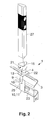
- FIG. 2 shows the device 1 with holding means 4 and insert 15.
- the guide post 27 can in the border 20 of the insert 15th be plugged in.
- the locking screw 21 which serves the border 20 of the insert 15 penetrates.
- the shown in Figure 2 Guardrail 3 has a smaller width (b2) than that shown in FIG Guardrail 3 with the width b1. Creating a horizontal, frictional connection is with the help of the screw 25, as well as the Covenants 22, 23 still possible.
- the bolt of the lower connecting part 10 in the sleeve designed as, upper Connecting part 9 is guided.
- the screw 13 penetrates the upper Jaw 6 and is bolted to the thread 12 of the bolt. As a result, the distance between the jaws 6, 7 depending on Need to be adjusted.
- the insert 15 can be inseparable from the device 1 connected is.
- the holding means 4 can be arranged as shown.
Landscapes
- Engineering & Computer Science (AREA)
- Architecture (AREA)
- Civil Engineering (AREA)
- Structural Engineering (AREA)
- Refuge Islands, Traffic Blockers, Or Guard Fence (AREA)
- Road Signs Or Road Markings (AREA)
Abstract
Description
- Fig. 1:
- eine Explosionsdarstellung der Befestigungsvorrichtung mit Straßenmarkierungsstangen, und
- Fig. 2:
- eine an einer Leitplanke angebrachte Befestigungsvorrichtung mit Einsatz zur Aufnahme eines Straßenleitpfostens.
- 1
- Vorrichtung
- 2
- Straßenmarkierungsstange
- 3
- Leitplanke
- 4
- Haltemittel
- 5
- Befestigungsmittel
- 6
- Klemmbacke
- 7
- Klemmbacke
- 8
- Verbindungsteil
- 9
- oberes Verbindungsteil
- 10
- unteres Verbindungsteil
- 11
- Schiene
- 12
- Gewinde
- 13
- Schraube
- 14
- Öffnung
- 15
- Einsatz
- 16
- Fortsatz
- 17
- Fixierschraube
- 18
- Boden
- 19
- Öffnung
- 20
- Umrandung
- 21
- Sicherungsschraube
- 22
- Bund
- 23
- Bund
- 24
- Vorderseite
- 25
- Schraube
- 26
- Hinterseite
- 27
- Leitpfosten
Claims (13)
- Vorrichtung zur Befestigung von Leitpfosten und/oder Schilderstangen und/oder Straßenmarkierungsstangen, insbesondere senkrechten Schneestangen, an Leitplanken, mit Haltemitteln zur Aufnahme eines Leitpfostens und/oder einer Schilderstange und/oder einer Straßenmarkierungsstange, sowie mit Befestigungsmitteln zur Befestigung der Vorrichtung an Leitplanken, dadurch gekennzeichnet, dass die Befestigungsmittel (5) aus mindestens zwei, voneinander beabstandeten, Klemmbacken (6, 7) bestehen, die über ein, insbesondere im wesentlichen senkrechtes, Verbindungsteil (8, 9 ,10) miteinander verbunden sind, wobei Mittel zur Einstellung des Abstandes zwischen den Klemmbacken und damit zur Herbeiführung einer kraftschlüssigen und/oder formschlüssigen Verbindung zwischen Vorrichtung (1) und Leitplanke (3), insbesondere in senkrechter Richtung, vorgesehen sind.
- Vorrichtung nach Anspruch 1, dadurch gekennzeichnet, dass die Mittel zur Einstellung des Abstandes der Klemmbacken als Gewinde- Schraubenkombination ausgebildet sind.
- Vorrichtung nach einem der vorhergehenden Ansprüche, dadurch gekennzeichnet, dass die Mittel zur Einstellung des Abstandes zwischen den Klemmbacken als Mittel zur Veränderung der wirksamen Länge des Verbindungsteils (8, 9, 10) ausgebildet sind.
- Vorrichtung nach Anspruch 2, dadurch gekennzeichnet, dass das Verbindungsteil (8) aus mindestens zwei Teilstücken (9, 10)besteht, die über mindestens eine Gewinde-Schraubenverbindung miteinander verbunden sind.
- Vorrichtung nach einem der vorhergehenden Ansprüche, dadurch gekennzeichnet, dass zur Herstellung eines Formschlusses, die Kontur der Klemmbacken (6, 7) an die Kontur der Ober- bzw. Unterkante der Leitplanke (3) angepasst ist.
- Vorrichtung nach einem der vorhergehenden Ansprüche, dadurch gekennzeichnet, dass das jede Klemmbacke (6, 7) einen, insbesondere im wesentlichen senkrechten, Bund (22, 23), zur Bildung eines Hintergriffs hinter die Vorder- (24) oder Rückseite (26) der Leitplanke (3), aufweist.
- Vorrichtung nach Anspruch 6, dadurch gekennzeichnet, dass Mittel zur Erzeugung einer kraftschlüssigen Verbindung der Befestigungsvorrichtung (1) mit der Leitplanke (3) in horizontaler Richtung vorgesehen sind.
- Vorrichtung nach Anspruch 7, dadurch gekennzeichnet, dass die Mittel als Mittel zum Anpressen der Bünde (22, 23) an die Leitplanke (3) ausgestaltet sind.
- Vorrichtung nach Anspruch 8, dadurch gekennzeichnet, dass als Mittel zum Anpressen der Bünde (22, 23) an die Leitplanke (3) mindestens eine, in einem, im wesentlichen horizontalen, Gewinde (26) geführte Schraube (25) vorgesehen ist, wobei das Gewinde (26) insbesondere in oder an dem Verbindungsteil (8, 9, 10, 11 ) an bzw. eingebracht ist.
- Vorrichtung nach einem der vorhergehenden Ansprüche, dadurch gekennzeichnet, dass als Haltemittel (4) zur Aufnahme einer Straßenmarkierungsstange (2) und/oder einer Schildstange, eine hülsenförmige, insbesondere zylindrische, Halterung (4), mit oder ohne Bodenanschlag vorgesehen ist, wobei die Halterung (4) vorzugsweise oberhalb der Befestigungsmittel, insbesondere oben mittig auf der Vorrichtung (1) angebracht ist.
- Vorrichtung nach einem der vorhergehenden Ansprüche, dadurch gekennzeichnet, dass ein Einsatz zum Ein- oder Aufstecken in/auf die Halterung (4) vorgesehen ist, der eine Einsteckaufnahme (20) zur Aufnahme eines Straßenleitpfostens (27) aufweist.
- Vorrichtung nach Anspruch 11, dadurch gekennzeichnet, dass die Kontur der Einsteckaufnahme (20) der, insbesondere im wesentlichen dreieckigen, Umfangskontur eines Leitpfostens (27) zuzüglich eines Spiels entspricht.
- Verwendung einer Vorrichtung mit den Merkmalen einer oder mehrer der Ansprüche 1 bis 12 zur Befestigung von Leitpfosten (27) und/oder Schilderstangen und/oder Straßenmarkierungsstangen (2), insbesondere senkrechte Schneestangen, an Leitplanken (3).
Applications Claiming Priority (2)
| Application Number | Priority Date | Filing Date | Title |
|---|---|---|---|
| DE10330770 | 2003-07-07 | ||
| DE10330770A DE10330770A1 (de) | 2003-07-07 | 2003-07-07 | Befestigungsvorrichtung |
Publications (2)
| Publication Number | Publication Date |
|---|---|
| EP1496158A2 true EP1496158A2 (de) | 2005-01-12 |
| EP1496158A3 EP1496158A3 (de) | 2005-12-28 |
Family
ID=33441655
Family Applications (1)
| Application Number | Title | Priority Date | Filing Date |
|---|---|---|---|
| EP04011497A Withdrawn EP1496158A3 (de) | 2003-07-07 | 2004-05-14 | Befestigungsvorrichtung |
Country Status (2)
| Country | Link |
|---|---|
| EP (1) | EP1496158A3 (de) |
| DE (1) | DE10330770A1 (de) |
Citations (1)
| Publication number | Priority date | Publication date | Assignee | Title |
|---|---|---|---|---|
| AT1253U1 (de) | 1996-03-19 | 1997-01-27 | Pointl Hartwig Ing | Vorrichtung zum befestigen von schneestangen |
Family Cites Families (8)
| Publication number | Priority date | Publication date | Assignee | Title |
|---|---|---|---|---|
| DE1817135U (de) * | 1958-10-30 | 1960-08-25 | Hans Rieger | Leitpfosten zur verkehrswegebegrenzungsmarkierung. |
| DE1929054U (de) * | 1965-09-03 | 1965-12-16 | Gubela K G | Halterung fuer einen leitpfosten an verkehrsstrassen. |
| FR2618814B1 (fr) * | 1987-07-31 | 1989-12-01 | Weiss Claude | Dispositif pour la fixation sur des rails de securite de panneaux |
| GB2263499A (en) * | 1992-01-27 | 1993-07-28 | Robert Ernest John Clarke | Road barrier bracket |
| DE9216724U1 (de) * | 1992-12-08 | 1993-04-01 | Ruchti, August, 8931 Mickhausen | Halterungsvorrichtung für Verkehrszeichen, insbesondere Leitpfosten |
| DE4423039A1 (de) * | 1994-07-01 | 1996-01-04 | Peter Siebs | Halterung für in Fahrbahnnähe einer Straße zu plazierende Einrichtungen |
| FR2799221B1 (fr) * | 1999-10-04 | 2001-11-23 | Csm Chaudronnerie De Saint Mar | Dispositif de fixation d'un panneau de signalisation routiere notamment sur une glissiere de securite |
| GB2370858A (en) * | 2001-01-06 | 2002-07-10 | Gerard James Walsh | Road traffic sign mounting bracket |
-
2003
- 2003-07-07 DE DE10330770A patent/DE10330770A1/de not_active Withdrawn
-
2004
- 2004-05-14 EP EP04011497A patent/EP1496158A3/de not_active Withdrawn
Patent Citations (1)
| Publication number | Priority date | Publication date | Assignee | Title |
|---|---|---|---|---|
| AT1253U1 (de) | 1996-03-19 | 1997-01-27 | Pointl Hartwig Ing | Vorrichtung zum befestigen von schneestangen |
Also Published As
| Publication number | Publication date |
|---|---|
| DE10330770A1 (de) | 2005-02-10 |
| EP1496158A3 (de) | 2005-12-28 |
Similar Documents
| Publication | Publication Date | Title |
|---|---|---|
| DE3640821C1 (en) | Protective barrier arrangement | |
| DE7627362U1 (de) | Warn-, markierungs- und/oder absperrvorrichtung | |
| EP0011199B1 (de) | Halteklemme | |
| DE19751625C2 (de) | Haltebügel zur Abstützung einer Absperrung an einer Gleisschiene | |
| DE29804162U1 (de) | Als Leiteinrichtung verwendbare Bake, insbesondere für den Straßenverkehr | |
| DE10250257B4 (de) | Straßenleitpfostenfuß | |
| EP1645691A1 (de) | Übergangskonstruktion | |
| DE19943229C2 (de) | Leitschwellenanordnung als schwenkbare Mittelstreifenschranke | |
| EP1496158A2 (de) | Befestigungsvorrichtung | |
| EP1094158B1 (de) | Verfahren und Vorrichtung zum Befestigen von Leitpflöcken, Leitschienen und dergleichen | |
| EP0697047B1 (de) | Vorrichtung zum verankern von pfosten von sicherheitsabsperrungen in einem fundament | |
| DE202007018693U1 (de) | Befestigungsvorrichtung für Straßenleitpfosten | |
| DE102008048810A1 (de) | Verkehrs-Leit-Einrichtung | |
| DE4341704A1 (de) | Halterung für Straßenverkehrszeichen | |
| DE8031263U1 (de) | Vorrichtung zur loesbaren im wesentlichen vertikalen befestigung von stangen an der der fahrbahn abgewandten seite von leitschienen an strassen, autobahnen usw. | |
| DE29801801U1 (de) | Leiteinrichtung | |
| DE10059080A1 (de) | Straßen-Schutz-Geländer-Stecksystem | |
| DE4007259A1 (de) | Pfahl fuer einfriedungen, insbesondere weidezaunpfahl | |
| DE2627005A1 (de) | Leit- und/oder warnvorrichtung an strassenraendern | |
| DE20016163U1 (de) | Halteelement für Schutzplanken | |
| DE202008006716U1 (de) | Mobile Absturzsicherung | |
| DE20119028U1 (de) | Straßen-Schutzgitter/Geländer-Stecksystem | |
| DE1863236U (de) | Haltevorrichtung fuer zu halternde teile, wie verkehrszeichen, blendschirme od. dgl. an autobahnen und strassen. | |
| DE8906460U1 (de) | Vorrichtung zum Begrenzen der Fahrbahnen von Kraftfahrzeugstraßen | |
| DE7125625U (de) | Hohlpfahl aus Stahl zur Halterung von Stangen, Pfosten und dergleichen |
Legal Events
| Date | Code | Title | Description |
|---|---|---|---|
| PUAI | Public reference made under article 153(3) epc to a published international application that has entered the european phase |
Free format text: ORIGINAL CODE: 0009012 |
|
| AK | Designated contracting states |
Kind code of ref document: A2 Designated state(s): AT BE BG CH CY CZ DE DK EE ES FI FR GB GR HU IE IT LI LU MC NL PL PT RO SE SI SK TR |
|
| AX | Request for extension of the european patent |
Extension state: AL HR LT LV MK |
|
| PUAL | Search report despatched |
Free format text: ORIGINAL CODE: 0009013 |
|
| AK | Designated contracting states |
Kind code of ref document: A3 Designated state(s): AT BE BG CH CY CZ DE DK EE ES FI FR GB GR HU IE IT LI LU MC NL PL PT RO SE SI SK TR |
|
| AX | Request for extension of the european patent |
Extension state: AL HR LT LV MK |
|
| AKX | Designation fees paid | ||
| STAA | Information on the status of an ep patent application or granted ep patent |
Free format text: STATUS: THE APPLICATION IS DEEMED TO BE WITHDRAWN |
|
| 18D | Application deemed to be withdrawn |
Effective date: 20060629 |
|
| REG | Reference to a national code |
Ref country code: DE Ref legal event code: 8566 |