EP1495909A2 - Kopfstütze für Fahrzeuge - Google Patents
Kopfstütze für Fahrzeuge Download PDFInfo
- Publication number
- EP1495909A2 EP1495909A2 EP04016031A EP04016031A EP1495909A2 EP 1495909 A2 EP1495909 A2 EP 1495909A2 EP 04016031 A EP04016031 A EP 04016031A EP 04016031 A EP04016031 A EP 04016031A EP 1495909 A2 EP1495909 A2 EP 1495909A2
- Authority
- EP
- European Patent Office
- Prior art keywords
- cushion units
- passenger
- cushion
- headrest
- units
- Prior art date
- Legal status (The legal status is an assumption and is not a legal conclusion. Google has not performed a legal analysis and makes no representation as to the accuracy of the status listed.)
- Withdrawn
Links
Images


Classifications
-
- B—PERFORMING OPERATIONS; TRANSPORTING
- B60—VEHICLES IN GENERAL
- B60N—SEATS SPECIALLY ADAPTED FOR VEHICLES; VEHICLE PASSENGER ACCOMMODATION NOT OTHERWISE PROVIDED FOR
- B60N2/00—Seats specially adapted for vehicles; Arrangement or mounting of seats in vehicles
- B60N2/80—Head-rests
- B60N2/885—Head-rests provided with side-rests
-
- B—PERFORMING OPERATIONS; TRANSPORTING
- B60—VEHICLES IN GENERAL
- B60N—SEATS SPECIALLY ADAPTED FOR VEHICLES; VEHICLE PASSENGER ACCOMMODATION NOT OTHERWISE PROVIDED FOR
- B60N2/00—Seats specially adapted for vehicles; Arrangement or mounting of seats in vehicles
- B60N2/80—Head-rests
- B60N2/806—Head-rests movable or adjustable
- B60N2/838—Tiltable
- B60N2/853—Tiltable characterised by their adjusting mechanisms, e.g. electric motors
-
- B—PERFORMING OPERATIONS; TRANSPORTING
- B60—VEHICLES IN GENERAL
- B60N—SEATS SPECIALLY ADAPTED FOR VEHICLES; VEHICLE PASSENGER ACCOMMODATION NOT OTHERWISE PROVIDED FOR
- B60N2/00—Seats specially adapted for vehicles; Arrangement or mounting of seats in vehicles
- B60N2/80—Head-rests
- B60N2/806—Head-rests movable or adjustable
- B60N2/838—Tiltable
- B60N2/856—Tiltable movable to an inoperative or stowed position
-
- B—PERFORMING OPERATIONS; TRANSPORTING
- B60—VEHICLES IN GENERAL
- B60N—SEATS SPECIALLY ADAPTED FOR VEHICLES; VEHICLE PASSENGER ACCOMMODATION NOT OTHERWISE PROVIDED FOR
- B60N2/00—Seats specially adapted for vehicles; Arrangement or mounting of seats in vehicles
- B60N2/80—Head-rests
- B60N2/888—Head-rests with arrangements for protecting against abnormal g-forces, e.g. by displacement of the head-rest
-
- B—PERFORMING OPERATIONS; TRANSPORTING
- B60—VEHICLES IN GENERAL
- B60N—SEATS SPECIALLY ADAPTED FOR VEHICLES; VEHICLE PASSENGER ACCOMMODATION NOT OTHERWISE PROVIDED FOR
- B60N2/00—Seats specially adapted for vehicles; Arrangement or mounting of seats in vehicles
- B60N2/02—Seats specially adapted for vehicles; Arrangement or mounting of seats in vehicles the seat or part thereof being movable, e.g. adjustable
- B60N2002/0204—Seats specially adapted for vehicles; Arrangement or mounting of seats in vehicles the seat or part thereof being movable, e.g. adjustable characterised by the seat or seat part turning about or moving along a non-standard, particular axis, i.e. an axis different from the axis characterising the conventional movement
- B60N2002/022—Seats specially adapted for vehicles; Arrangement or mounting of seats in vehicles the seat or part thereof being movable, e.g. adjustable characterised by the seat or seat part turning about or moving along a non-standard, particular axis, i.e. an axis different from the axis characterising the conventional movement the seat or seat part turning about or moving along a vertical axis
Definitions
- the present invention relates to a headrest for vehicles, and more particularly to a headrest for vehicles, which can fixedly support the passenger's head including the mandible in an automobile crash, thereby preventing sprain due to hyper-flexion of the neck.
- an automotive vehicle seat is provided at the top of a backrest with a headrest for supporting the passenger's occiput.
- a headrest serves to relieve shock applied to the occiput in an automobile crash, thereby minimizing injury to the passenger.
- headrests are designed to only to support the passenger's occiput, they have a problem in that they cannot provide protection to the neck, in spite of the fact that the neck is an extremely fragile region of the human body, in an automobile crash.
- Figs. 9a and 9b are, respectively, a plan view and a side view.
- the device shown is disclosed in Korean Registration Patent Publication No. 302153, titled in "AUXILIARY SUPPORT DEVICE OF HEADREST FOR VEHICLES".
- a headrest 200 installed at the top of a backrest 101 of a conventional automotive vehicle seat 100, comprises a pair of support rods 220 fitted at the top of the backrest 101, and a head cushion 210 fitted at the top of the support rods 220 for supporting the passenger's occipital bone.
- the auxiliary support device 300 comprises an air bag 310, and a plurality of springs 320 for elastically supporting the rear surface of the air bag 310.
- the above described conventional headrest provided with the auxiliary support device, can relieve shock generated at the moment of an automobile crash by supporting the passenger's occiput as well as the scruff of the neck at the rear side thereof, it cannot prevent hyperflexion of the neck caused as the passenger's head rebounds forward, thereby potentially causing sprain to the passenger' neck.
- Such sprain is caused due to the fact that the passenger's head is not stably immobilized so as not to move in an automobile crash.
- the passenger wears a safety belt and thus his/her body is stably immobilized, especially, a larger moment is applied to the passenger's neck, resulting in a risk of whiplash due to hyperflexion.
- Such a risk has awakened us to the urgent need for appropriate measures to safeguard passengers.
- the present invention has been made in view of the above problems, and it is an object of the present invention to provide a headrest for vehicles, which can fixedly support the passenger's head including the mandible in an automobile crash, thereby preventing sprain due to hyperflexion of the neck.
- a headrest for a vehicle comprising: a pair of support rods fitted at the top of a backrest of an automotive vehicle seat; first and second cushion units rotatably fitted at the top of the respective support rods, respectively; at least one elastic member for elastically connecting the first and second cushion units; jaw-restraint portions formed at opposite sides of the first and second cushion units, respectively; and stoppers for keeping the support rods in an immobilized state after the first and second cushion units are rotated to a predetermined degree.
- the first and second cushion units include: a pair of symmetrical seating portions, respectively, formed at positions corresponding to the passenger's occipital bone; and a pair of auxiliary cushion members located below the respective seating portions for supporting the bottom of the occipital bone.
- a headrest for a vehicle comprising: first and second cushion units rotatably fitted at the top of a pair of support rods, respectively, the support rods being fitted at the top of a backrest of an automotive vehicle seat, the first and second cushion units having jaw-restraint portions formed at opposite sides thereof, respectively; impact sensors for detecting shock applied to the vehicle in an automobile crash, and outputting signals; pressure sensors for detecting shock caused as the passenger's head collides against the first and second cushion units, and outputting signals; a control unit for receiving the signals from the impact sensor and the pressure sensors, and outputting a control signal for causing rotation of the first and second cushion units; driving units for rotating the first and second cushion units according to the control signal; and stoppers for keeping the first and second cushion units in an immobilized state after they are rotated by a predetermined degree.
- a headrest for a vehicle comprising: first and second cushion units rotatably fitted at the top of a pair of support rods, respectively, the support rods being fitted at the top of a backrest of an automotive vehicle seat, the first and second cushion units having jaw-restraint portions formed at opposite sides thereof, respectively; impact sensors for detecting shock applied to the vehicle in an automobile crash, and outputting signals; a distance adjustment unit for maintaining a constant distance between the passenger's head and the first and second cushion units; a control unit for receiving the signals from the impact sensor, and outputting a control signal for causing rotation of the first and second cushion units; driving units for rotating the first and second cushion units according to the control signal; and stoppers for keeping the first and second cushion units in an immobilized state after they are rotated by a predetermined degree.
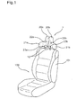
- Fig. 1 is a perspective view illustrating an automotive vehicle seat provided with a headrest in accordance with a first embodiment of the present invention.
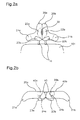
- Figs. 2a and 2b are a front view and a plan view, respectively, illustrating the headrest shown in Fig. 1.
- a headrest for vehicles in accordance with a first embodiment of the present invention which is designated as reference numeral 1, comprises: a pair of support rods 10 fitted at the top of the backrest 101 of the automotive vehicle seat 100; first and second cushion units 20a and 20b rotatably installed at the top of the respective support rods 10; an elastic member 30 for elastically connecting the first and second cushion units 20a and 20b; a jaw-restraint portions 21a and 21b formed at opposite sides of the first and second cushion units 20a and 20b, respectively; and a pair of stoppers 40a and 40b for stopping rotation of the first and second cushion units 20a and 20b after they completely surround the passenger's head.
- first and second cushion units 20a and 20b are disposed cylindrical sleeves 24a and 24b, respectively, for use in the insertion of the respective support rods 10. These sleeves 24a and 24b enable the first and second cushion units 20a and 20b to freely rotate about the respective support rods 10.
- the jaw-restraint portions 21a and 21b formed at the opposite sides of the first and second cushion units 20a and 20b, protrude forward so that they can surround the passenger's head including the mandible as the first and second cushion units 20a and 20b rotate about the support rods 10.
- the stoppers 40a and 40b are disposed within the first and second cushion units 20a and 20b. At the moment when the jaw-restraint portions 21a and 21b completely surround the passenger's head, the stoppers 40a and 40b serve to stop rotation of the first and second cushion units 20a and 20b in order to immobilize the passenger's head. Detailed description related to the operation of the stoppers 40a and 40b will follow with reference to Fig. 3.
- concave seating portions 22a and 22b are positioned in correspondence to the passenger's occipital bone, so as to closely support the occipital bone, thereby serving to allowing shock applied to the occipital bone in an automobile crash to be rapidly distributed and thus providing protection to the brain.
- auxiliary cushion members 23a and 23b Attached at the front surfaces of the first and second cushion units 20a and 20b below the concave seating portions 22a and 22b are auxiliary cushion members 23a and 23b for supporting the bottom of the occipital bone. These auxiliary cushion members 23a and 23b serve to lessen load of the head to be transmitted to the backbone, resulting in a comfortable ride for the passenger.
- the auxiliary cushion members 23a and 23b are made of memory foam so that they come into close contact with the occipital bone regardless of different occipital bone's shapes in order to multiply the comfort of the ride.
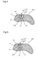
- Fig. 3 is a plan view illustrating the operation of the headrest 1 shown in Fig. 2b.
- Fig. 4 is a cross-sectional view illustrating the stopper 40b shown in Fig. 2b.
- the stopper 40b comprises: a case 41 provided inside the second cushion unit 20b; the latch 42 protruding at one end thereof out of the case 41 so as to come into contact with the outer periphery of the support rod 10 within the second cushion unit 20b; the spring 43 disposed inside the case 41 so as to elastically support the other end of the latch 42; the fixing groove 44 defined at the outer periphery of the support rod 10 for allowing the latch 42 to be lockably engaged therein as a result of rotation of the second cushion unit 20b; and a pulling member 45 for pulling out the latch 42 inserted in the fixing groove 44.
- latches 42 formed at the stoppers 40a and 40b are coincided with fixing grooves 44 defined at the outer periphery of the respective support rods 10, and lockably engaged in the fixing grooves 44 by the elasticity of springs 43, thereby allowing the first and second cushion units 20a and 20b to be fixedly maintained at such a rotated position.
- the sleeves 24a and 24b have through-bores (not designated), respectively, for allowing the end of the respective latches 42 to come into contact with the outer periphery of the respective support rods 10 therethrough.
- shock which is generated in the course of the collision of the passenger's head against the first and second cushion units 20a and 20b, is exhausted largely by virtue of the elasticity of the elastic member 30, resulting in effective reduction of the shock transmitted to the brain of the passenger.
- jaw-restraint portions 21a and 21b are immobilized in a state that they completely surround the passenger's head including the mandible, thereby serving to effectively restrict further movement of the head, sprain due to hyperflexion of the neck can be completely prevented.
- each of the pulling members 45 has a wire 450, which is connected at one end thereof to the other end of the corresponding latch 42. The other end of the wire 450 protrudes out of the cushion unit.
- the pulling member 45 further has a pull grip 451 provided at the outwardly-protruded end of the wire 450.
- the latches 42 are drawn from the fixing grooves 44 by means of the wires 450, thereby allowing the first and second cushion units 20a and 20b to be released from their immobilized state.
- the released first and second cushion units 20a and 20b are automatically returned to their original positions by the elasticity of the elastic member 30.
- Fig. 5 is a cross-sectional view illustrating another example of the stopper shown in Fig. 2b.
- the shown example is different from the above embodiment in that springs 43', used to elastically support the other end of the respective latches 42 are plate springs rather than coil springs.
- Fig. 6 is a cross-sectional view illustrating a headrest in accordance with a second embodiment of the present invention.
- Fig. 7 is a front sectional view illustrating a driving unit for use in the headrest shown in Fig. 6.
- signals from impact sensors (not shown) mounted in an automotive vehicle are inputted into a control unit (not shown).
- a control unit In succession, as the passenger's occiput is rapidly moved back due to such an automobile crash, and collides against the first and second cushion units 20a and 20b, pressure sensors (not shown) disposed inside the first and second cushion units 20a and 20b detect shock applied thereto by the passenger's head, thereby sending signals to the control unit.
- the control unit Upon receiving the above described signals, the control unit outputs a control signal to driving units, so that the first and second cushion units 20a and 20b, and the sleeves 24a and 24b disposed therein are rotated about the support rods 10 according to the operation of the driving units. In this way, the first and second cushion units 20a and 20b are adapted to surround the passenger's head.
- the second embodiment employs a pair of stoppers, which are different from those of the first embodiment.
- the stopper comprises: a first detector 46 positioned just inside the outer periphery of the support rod 10; a second detector 47 positioned just inside the inner periphery of the sleeve 24b, which surrounds the support rod 10, so as to correspond to the first detector 46; and a locking member 48 adapted to support the lateral surface of the support rod 10 when positions of the first and second detectors 46 and 47 coincide with each other as a result of rotation of the second cushion unit 20b, thereby serving to stop rotation of the second cushion unit 20b and maintaining it in an immobilized state.
- the above configuration is also applicable to the stopper of the first cushion unit 20a.
- Each of the locking members 48 serves to immobilize the first and second cushion units 20a and 20b by making use of a frictional force.
- Each of the locking members 48 comprises: a hydraulic or pneumatic cylinder 480; a clamp 481 which comes into close contact with the support rod 10 under operation of the cylinder 480 so as to generate a frictional force; and the control unit (not shown) for receiving a signal generated when positions of the first and second detectors 46 and 47 coincide with each other, and sending a driving signal to the cylinder 480.
- the cylinder 480 In order to release such an immobilized state of the first and second cushion units 20a and 20b, the cylinder 480 must be driven so as to remove a pressure applied to the clamp 481. Such a pressure removal operation can be easily achieved by installing a separate operator unit (not shown) for inputting a release signal to the control unit.
- the driving unit designated as reference numeral 50, has a servo-motor 51 fixed inside the second cushion unit 20b, and a power-transmission member 52 for transmitting a rotating force of the servo-motor 51 to the support rod 10 inside the second cushion unit 20b.
- the power-transmission member 52 transmits the rotating force of the servo-motor 51 to the second cushion unit 20b, thereby allowing the second cushion unit 20b to rotate about the support rod 10.
- a power-transmission member 52 consists of a driving gear (not designated) provided at the servo-motor 51, and a driven gear (not designated) fitted around the support rod 10 so as to engage with the driving gear.
- the control unit drives the servo-motor 51 so as to rotate the driving gear.
- the driving gears rotate around the driven gears fitted to the respective support rods 10
- the first and second cushion units 20a and 20b are automatically rotated so as to fixedly support the passenger's head.
- a time required for the backward movement of the passenger's head by inertia in an automobile crash may be previously calculated and stored in the control unit. Thereby, after the control unit detects an automobile crash, the first and second cushion units 20a and 20b are rotated by a predetermined time interval depending on the stored data.
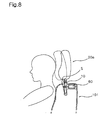
- Fig. 8 is a side sectional view illustrating a headrest in accordance with a third embodiment of the present invention.
- the present embodiment employs a distance adjustment unit for allowing the first and second cushion units 20a and 20b at the top of the backrest 101 to be equally moved toward the passenger's head according to the position of the head. By such a distance adjustment unit, therefore, the first and second cushion units 20a and 20b can closely support the passenger's head.
- the present embodiment enables the first and second cushion units 20a and 20b to be closely spaced from the passenger's head, thereby allowing the first and second cushion units 20a and 20b to freely rotate regardless of the collision direction of an automotive vehicle. This secures accurate and stable supporting of the passenger's head.
- the distance adjustment unit comprises: a distance sensor (S) for detecting a distance between the passenger's occipital bone and the first and second cushion units 20a and 20b, and outputting a corresponding signal; the control unit for detecting the signal from the sensor (S), and outputting a control signal if the detected distance exceeds a predetermined value; and a position adjustor 60 for adjusting positions of the first and second cushion units 20a and 20b according to the control signal.
- the distance sensor (S) is selected from among conventional photo-sensors, ultrasonic sensors, etc. Such a distance sensor (S) is installed between the support rods 10, and is adapted to measure the distance between the occiput or neck of the passenger and the support rods 10, thereby allowing the distance to be kept in a constant value.
- such a distance adjustment is achieved by adjusting an inclination angle of the first and second cushion units 20a and 20b.
- the support rods 10 are hingedly fixed at their lower ends inside the backrest 101, and the position adjustor 60, which is also fixed inside the backrest 101, serves to allow the first and second cushion units 20a and 20b to be pivotably rotated by a desired angle.
- the position adjustor 60 is used a conventional cylinder.
- the control unit In a state wherein a desired distance value between the first and second cushion units and the passenger's head is previously set in the control unit, only when the distance value detected by the distance sensor (S) exceeds the desired preset value, the control unit is adapted to output a control signal to the position adjustor 60.
- the first and second cushion units 20a and 20b are pivotably rotated in an automobile crash so as to fixedly support the passenger's head.
- the first and second cushion units 20a and 20b are automatically pivoted corresponding to the position of the passenger's occipital bone, thereby keeping a constant distance relative to the passenger's head. This enables rapid and accurate support of the passenger's head even if the head is moved laterally in case of a broadside collision.
- the present embodiment employs a separate manually-operated switch provided at an automotive vehicle for selectively operating the distance adjustment unit as occasion demands by controlling a power source of the distance adjustment unit. Further, in order to allow positions of the first and second cushion units to be selectively adjusted by the distance adjustment unit only when a passenger rides in the vehicle, the vehicle is provided with a seat sensor for detecting the presence of the passenger on the vehicle seat.
- the first and second cushion units are automatically pivoted in boarding, or automatically stopped in alighting.
- the seat sensor serves to confirm the presence of the passenger, and is selectable from among various types of sensors, for example, pressure-sensitive sensors, which are usually installed on a vehicle seat for detecting the weight of the passenger, and sensors, which are usually installed in the vehicle for detecting ignition of the vehicle.
- sensors for example, pressure-sensitive sensors, which are usually installed on a vehicle seat for detecting the weight of the passenger, and sensors, which are usually installed in the vehicle for detecting ignition of the vehicle.
- the present invention provides a headrest for vehicles, which can fixedly support the passenger's head including the mandible in an automobile crash, thereby preventing sprain due to hyperflexion of the neck. This has an effect of minimizing injury to the neck of the passenger. Especially, in spite of the fact that the passenger's neck is further endangered when the passenger wears a safety belt, the headrest of the present invention can effectively protect the passenger's neck, and can secure the greatest safety of the passenger.
- shock applied to the occiput in an automobile crash can be rapidly distributed, resulting in minimization in transmission of the shock to the brain.
- auxiliary cushion members therebelow for supporting the bottom of the occiput, it is possible to allow lessen load of the passenger's head to be transmitted to the backbone, resulting in a more comfortable ride.
- the first and second cushion units may be adapted to automatically support the passenger's head in an automobile crash. This enables more rapid and accurate support of the head and thus results in more successful lifesaving.
- the first and second cushion units are adapted to automatically keep a constant distance relative to the passenger's head according to position of the head, and thus rapidly support the head, it is possible to protect the passenger's head in an automobile crash regardless of the posture of the passenger or the collision direction of an automotive vehicle.
- a distance adjustment unit for adjusting a distance between the first and second cushion units and the passenger's occipital bone, is constructed so as to be automatically turned on/off according to the presence of the passenger without requiring a separate switch manipulation, resulting in simplified control in operation of the first and second cushion units.
Applications Claiming Priority (4)
| Application Number | Priority Date | Filing Date | Title |
|---|---|---|---|
| KR2003046196 | 2003-07-08 | ||
| KR20030046196 | 2003-07-08 | ||
| KR2004044149 | 2004-06-15 | ||
| KR1020040044149A KR100584907B1 (ko) | 2003-07-08 | 2004-06-15 | 차량용 헤드레스트 |
Publications (1)
| Publication Number | Publication Date |
|---|---|
| EP1495909A2 true EP1495909A2 (de) | 2005-01-12 |
Family
ID=33455698
Family Applications (1)
| Application Number | Title | Priority Date | Filing Date |
|---|---|---|---|
| EP04016031A Withdrawn EP1495909A2 (de) | 2003-07-08 | 2004-07-07 | Kopfstütze für Fahrzeuge |
Country Status (3)
| Country | Link |
|---|---|
| US (1) | US20050006941A1 (de) |
| EP (1) | EP1495909A2 (de) |
| JP (1) | JP2005028142A (de) |
Cited By (7)
| Publication number | Priority date | Publication date | Assignee | Title |
|---|---|---|---|---|
| FR2917344A1 (fr) * | 2007-06-15 | 2008-12-19 | Airbus France Sas | Appui-tete multimodal pour siege de vehicule |
| EP2033851A3 (de) * | 2007-09-07 | 2010-03-10 | Daimler AG | Fahrzeugsitz für ein Kraftfahrzeug |
| EP2200872A1 (de) * | 2007-09-20 | 2010-06-30 | Richard Gale Scarf | Fahrzeuginsassenkopfschutz |
| RU2515824C1 (ru) * | 2013-04-30 | 2014-05-20 | Виктор Михайлович Коршунов | Приставка к подголовнику кресла транспортного средства |
| CN104648196A (zh) * | 2014-09-06 | 2015-05-27 | 冯逸凡 | 一种护脖头枕 |
| WO2016049691A1 (en) * | 2014-09-30 | 2016-04-07 | Cj Albert Builders Pty Ltd | Head and neck rest |
| IT201800010160A1 (it) * | 2018-11-08 | 2020-05-08 | Matteo Tomaiuolo | "poggiatesta per veicoli atto a limitare i danni da colpi di frusta" |
Families Citing this family (19)
| Publication number | Priority date | Publication date | Assignee | Title |
|---|---|---|---|---|
| JP4578262B2 (ja) * | 2005-02-10 | 2010-11-10 | 株式会社フジクラ | 頭部検知機能付きヘッドレスト及びヘッドレスト制御システム |
| JP2007022450A (ja) * | 2005-07-20 | 2007-02-01 | Aisin Seiki Co Ltd | 車両用シート装置 |
| JP4358255B2 (ja) * | 2007-04-20 | 2009-11-04 | トヨタ紡織株式会社 | 車両用シート |
| KR100973113B1 (ko) | 2008-03-25 | 2010-07-29 | 김민수 | 다기능 자동차 헤드 레스트 |
| JP5323558B2 (ja) * | 2009-03-30 | 2013-10-23 | 日本発條株式会社 | ヘッドレスト装置 |
| JP5323557B2 (ja) * | 2009-03-30 | 2013-10-23 | 日本発條株式会社 | ヘッドレスト装置 |
| US9196175B2 (en) * | 2010-03-30 | 2015-11-24 | Michael C. Walsh | Ergonomic sensor pad with feedback to user and method of use |
| DE102010054651A1 (de) * | 2010-12-15 | 2012-06-21 | Fachhochschule Kaiserslautern | Kopfstütze zum Schutz der Halswirbelsäule |
| CN103338734B (zh) * | 2010-12-28 | 2016-04-20 | 丰田自动车株式会社 | 移乘辅助装置及其工作方法 |
| DE102011121120B3 (de) * | 2011-12-14 | 2013-06-13 | Faurecia Autositze Gmbh | Kopfstütze für Kraftfahrzeugsitze |
| DE102012000426A1 (de) * | 2012-01-12 | 2013-07-18 | GM Global Technology Operations LLC (n. d. Gesetzen des Staates Delaware) | Kopfstütze für einen Fahrzeugsitz |
| US8651570B2 (en) | 2012-04-19 | 2014-02-18 | Terri L. Brucato | Protective headrest |
| US9905106B2 (en) | 2015-09-25 | 2018-02-27 | The Boeing Company | Ergonomics awareness chairs, systems, and methods |
| US10099591B2 (en) * | 2016-12-01 | 2018-10-16 | David Flynn | Dual configuration headrest system |
| JP2018144507A (ja) * | 2017-03-01 | 2018-09-20 | トヨタ紡織株式会社 | 乗物用ヘッドレスト |
| JP6750643B2 (ja) * | 2018-03-22 | 2020-09-02 | トヨタ自動車株式会社 | 車両用シート構造 |
| CN113646209A (zh) * | 2019-04-02 | 2021-11-12 | 盖斯廷德股份有限公司 | 一种车辆座椅 |
| US10893754B1 (en) | 2020-04-09 | 2021-01-19 | Jay Patrick Cooke | Modular and adjustable headrest |
| US20230373370A1 (en) * | 2022-05-19 | 2023-11-23 | GM Global Technology Operations LLC | Adjustable headrest |
Family Cites Families (10)
| Publication number | Priority date | Publication date | Assignee | Title |
|---|---|---|---|---|
| JPS4739054Y1 (de) * | 1967-11-20 | 1972-11-27 | ||
| JPS5022299B1 (de) * | 1970-06-30 | 1975-07-30 | ||
| JPS6111358U (ja) * | 1984-06-28 | 1986-01-23 | 池田物産株式会社 | 回転式ヘツドレスト |
| JPH04279109A (ja) * | 1991-03-05 | 1992-10-05 | Eiichiro Tanaka | いす用ヘッドレスト |
| JPH0661152U (ja) * | 1993-02-12 | 1994-08-30 | ダイハツ工業株式会社 | ヘッドレストの前後位置自動調整装置 |
| JPH08187139A (ja) * | 1995-01-06 | 1996-07-23 | Nec Home Electron Ltd | 車載ヘッドレスト装置 |
| JPH1134711A (ja) * | 1997-05-19 | 1999-02-09 | Araco Corp | 車両用シートのヘッドレスト |
| JP4024428B2 (ja) * | 1999-06-16 | 2007-12-19 | ジョンソン コントロールズ オートモーティブ システムズ株式会社 | 車両のフラット化シート構造 |
| JP4300657B2 (ja) * | 1999-10-22 | 2009-07-22 | 株式会社豊田中央研究所 | 車両用シート |
| JP2002019555A (ja) * | 2000-07-07 | 2002-01-23 | Takata Corp | 乗員保護装置 |
-
2004
- 2004-07-07 US US10/886,424 patent/US20050006941A1/en not_active Abandoned
- 2004-07-07 EP EP04016031A patent/EP1495909A2/de not_active Withdrawn
- 2004-07-08 JP JP2004201293A patent/JP2005028142A/ja active Pending
Cited By (11)
| Publication number | Priority date | Publication date | Assignee | Title |
|---|---|---|---|---|
| FR2917344A1 (fr) * | 2007-06-15 | 2008-12-19 | Airbus France Sas | Appui-tete multimodal pour siege de vehicule |
| WO2009004211A3 (fr) * | 2007-06-15 | 2010-01-14 | AIRBUS OPERATIONS (Société par actions simplifiée) | Appui-tête multimodal pour siège de véhicule |
| US8342606B2 (en) | 2007-06-15 | 2013-01-01 | Airbus Operations Sas | Multimodal headrest for vehicle seat |
| RU2471653C2 (ru) * | 2007-06-15 | 2013-01-10 | Эрбюс Операсьон (С.А.С) | Многофункциональный подголовник для кресла транспортного средства |
| EP2033851A3 (de) * | 2007-09-07 | 2010-03-10 | Daimler AG | Fahrzeugsitz für ein Kraftfahrzeug |
| EP2200872A1 (de) * | 2007-09-20 | 2010-06-30 | Richard Gale Scarf | Fahrzeuginsassenkopfschutz |
| EP2200872A4 (de) * | 2007-09-20 | 2012-09-19 | Richard Gale Scarf | Fahrzeuginsassenkopfschutz |
| RU2515824C1 (ru) * | 2013-04-30 | 2014-05-20 | Виктор Михайлович Коршунов | Приставка к подголовнику кресла транспортного средства |
| CN104648196A (zh) * | 2014-09-06 | 2015-05-27 | 冯逸凡 | 一种护脖头枕 |
| WO2016049691A1 (en) * | 2014-09-30 | 2016-04-07 | Cj Albert Builders Pty Ltd | Head and neck rest |
| IT201800010160A1 (it) * | 2018-11-08 | 2020-05-08 | Matteo Tomaiuolo | "poggiatesta per veicoli atto a limitare i danni da colpi di frusta" |
Also Published As
| Publication number | Publication date |
|---|---|
| JP2005028142A (ja) | 2005-02-03 |
| US20050006941A1 (en) | 2005-01-13 |
Similar Documents
| Publication | Publication Date | Title |
|---|---|---|
| EP1495909A2 (de) | Kopfstütze für Fahrzeuge | |
| US5769489A (en) | Energy absorbing support for vehicular passengers | |
| US5908219A (en) | Restraining system for vehicle occupants | |
| US7748781B2 (en) | Head and body protection child safety seat | |
| US5975637A (en) | Adjustable vehicle seat | |
| US7404402B2 (en) | Whiplash restrainer | |
| JP2002501988A (ja) | レース用の改良された頭部・首部支持物 | |
| US5806933A (en) | Head rest and restraint assembly | |
| EP0677423B1 (de) | Nackenstütze für Fahrzeugsitze | |
| US3713694A (en) | Body restraining device for vehicle | |
| JPH06500748A (ja) | 自動車内の安全装置 | |
| US5765893A (en) | Apparatus for reducing head and neck injuries in infants riding in moving vehicles | |
| US11052796B2 (en) | Vehicle seat | |
| AU722856B2 (en) | Impact pad for a safety seat | |
| US20230365098A1 (en) | Vehicle seat device | |
| US5749599A (en) | Vehicle air bag guard | |
| RU2620144C1 (ru) | Адаптивное транспортное кресло повышенной безопасности | |
| JP2005501771A (ja) | 後部衝突の場合にヘッドレストを移動させる方法および車両シート上のヘッドレストの配置 | |
| KR200326836Y1 (ko) | 자동차용 의자의 목-머리 받침대 | |
| US6938926B2 (en) | Safety device for a comfortable seat | |
| KR100584907B1 (ko) | 차량용 헤드레스트 | |
| EP0322948A1 (de) | Polstersitz mit einer Sicherheitsvorrichtung für den Insassen eines Kraftwagens | |
| JP4421585B2 (ja) | シート着座補助装置 | |
| JP3799823B2 (ja) | 車両用シート構造 | |
| SI9600306A (sl) | Pripomoček za varovanje vratu voznika ali potnika, varovanega s čelado in varnostnim pasom |
Legal Events
| Date | Code | Title | Description |
|---|---|---|---|
| PUAI | Public reference made under article 153(3) epc to a published international application that has entered the european phase |
Free format text: ORIGINAL CODE: 0009012 |
|
| 17P | Request for examination filed |
Effective date: 20040707 |
|
| AK | Designated contracting states |
Kind code of ref document: A2 Designated state(s): AT BE BG CH CY CZ DE DK EE ES FI FR GB GR HU IE IT LI LU MC NL PL PT RO SE SI SK TR |
|
| AX | Request for extension of the european patent |
Extension state: AL HR LT LV MK |
|
| STAA | Information on the status of an ep patent application or granted ep patent |
Free format text: STATUS: THE APPLICATION IS DEEMED TO BE WITHDRAWN |
|
| 18D | Application deemed to be withdrawn |
Effective date: 20070201 |