EP1495347B1 - Blankgepresste Linse - Google Patents
Blankgepresste Linse Download PDFInfo
- Publication number
- EP1495347B1 EP1495347B1 EP03718740A EP03718740A EP1495347B1 EP 1495347 B1 EP1495347 B1 EP 1495347B1 EP 03718740 A EP03718740 A EP 03718740A EP 03718740 A EP03718740 A EP 03718740A EP 1495347 B1 EP1495347 B1 EP 1495347B1
- Authority
- EP
- European Patent Office
- Prior art keywords
- lens
- edge
- supporting edge
- pressed
- width
- Prior art date
- Legal status (The legal status is an assumption and is not a legal conclusion. Google has not performed a legal analysis and makes no representation as to the accuracy of the status listed.)
- Expired - Lifetime
Links
Images
Classifications
-
- G—PHYSICS
- G02—OPTICS
- G02B—OPTICAL ELEMENTS, SYSTEMS OR APPARATUS
- G02B3/00—Simple or compound lenses
- G02B3/02—Simple or compound lenses with non-spherical faces
-
- C—CHEMISTRY; METALLURGY
- C03—GLASS; MINERAL OR SLAG WOOL
- C03B—MANUFACTURE, SHAPING, OR SUPPLEMENTARY PROCESSES
- C03B11/00—Pressing molten glass or performed glass reheated to equivalent low viscosity without blowing
- C03B11/06—Construction of plunger or mould
- C03B11/08—Construction of plunger or mould for making solid articles, e.g. lenses
-
- C—CHEMISTRY; METALLURGY
- C03—GLASS; MINERAL OR SLAG WOOL
- C03B—MANUFACTURE, SHAPING, OR SUPPLEMENTARY PROCESSES
- C03B11/00—Pressing molten glass or performed glass reheated to equivalent low viscosity without blowing
- C03B11/12—Cooling, heating, or insulating the plunger, the mould, or the glass-pressing machine; cooling or heating of the glass in the mould
- C03B11/125—Cooling
-
- C—CHEMISTRY; METALLURGY
- C03—GLASS; MINERAL OR SLAG WOOL
- C03B—MANUFACTURE, SHAPING, OR SUPPLEMENTARY PROCESSES
- C03B35/00—Transporting of glass products during their manufacture, e.g. hot glass lenses, prisms
-
- F—MECHANICAL ENGINEERING; LIGHTING; HEATING; WEAPONS; BLASTING
- F21—LIGHTING
- F21S—NON-PORTABLE LIGHTING DEVICES; SYSTEMS THEREOF; VEHICLE LIGHTING DEVICES SPECIALLY ADAPTED FOR VEHICLE EXTERIORS
- F21S41/00—Illuminating devices specially adapted for vehicle exteriors, e.g. headlamps
- F21S41/20—Illuminating devices specially adapted for vehicle exteriors, e.g. headlamps characterised by refractors, transparent cover plates, light guides or filters
- F21S41/25—Projection lenses
-
- G—PHYSICS
- G02—OPTICS
- G02B—OPTICAL ELEMENTS, SYSTEMS OR APPARATUS
- G02B7/00—Mountings, adjusting means, or light-tight connections, for optical elements
- G02B7/02—Mountings, adjusting means, or light-tight connections, for optical elements for lenses
- G02B7/022—Mountings, adjusting means, or light-tight connections, for optical elements for lenses lens and mount having complementary engagement means, e.g. screw/thread
-
- C—CHEMISTRY; METALLURGY
- C03—GLASS; MINERAL OR SLAG WOOL
- C03B—MANUFACTURE, SHAPING, OR SUPPLEMENTARY PROCESSES
- C03B2215/00—Press-moulding glass
- C03B2215/40—Product characteristics
- C03B2215/46—Lenses, e.g. bi-convex
- C03B2215/49—Complex forms not covered by groups C03B2215/47 or C03B2215/48
Definitions
- the invention relates to a lens according to the preamble of patent claim 1, a use of the lens and a manufacturing method.
- the J59-177506 A describes lenses of a projection lens, wherein the two outer lenses of the lens have a relation to the planar lens surface protruding support edge, which is designed stepped.
- the shoulder thus produced serves to rest on another lens, namely a biconvex lens, with the aim of defining a distance between the lenses.
- the JP59-157603 A shows two lenses having abutment edges, on whose outer periphery protrusions are provided with inclined surfaces. Due to this configuration, emphasis is placed on high precision and stability of the edges.
- the object of the invention is to provide a manufacturing method in which such a post-processing process, such as grinding and polishing, is eliminated.
- the two-sided molding eliminates the need for post-processing.
- the two-sided molding is possible because there is a support edge, which offers the advantage that the lens when depositing on a pad rests exclusively with this support edge and contact of the flat surface is avoided with the support, so that the flat lens surface is not damaged becomes.
- a blank pressed on both sides with a support edge can thus be laid on a conveyor belt, for example a cooling oven, without problems.
- the bearing edge is integrally formed on the outer circumference of the lens.
- the retaining edge is integrally formed on the outside of the lens and the support edge is formed on this retaining edge, the support edge is located outside the beam path and thus outside the optically effective surface of the lens.
- the thickness D of the support edge is at least 0.2 mm. This minimum thickness is necessary so that any unevenness on the support surface, especially on a cooling belt, does not lead to contact with the flat surface.
- the width B 1 of the support edge is less than or equal to the width B 2 of the retaining edge.
- a lens pressed on both sides with a curved surface, with a planar surface and with a retaining edge formed on the edge of the lens, on which a support surface projecting from the planar surface is formed is used for projection headlights for motor vehicles.
- the method for producing a lens with a curved surface and with a plane surface provides that at the lens edge, a retaining edge and a support edge projecting on the retaining edge against the flat surface is formed and that both surfaces are blank pressed.
- the lens is deposited during the cooling process on the support edge.
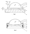
- the lens 1 is shown in cross-section.
- the lens has an aspherical surface 2 and a planar surface 3.
- a retaining edge 4 is formed, which merges in its outer region in a bearing edge 5, which projects from the flat surface 3.
- the lens is only by means of Auflagerandes 5, so that the flat lens surface 3 can not be damaged.
- the support edge 5 is about its thickness D equal to about 0.3 mm from the surface 3 before.
- the width B 1 of the supporting rim 5 is less than the width B 2 of the holding rim 4, so that the optically effective area of the planar surface 3 is not limited. If it is a lens 1 pressed on both sides, it can easily be stored and transported after the blank pressing process or can be supplied with further cooling steps without damaging the lens surface.
- FIG. 2 is the installed state of the lens 1, z. B. as a projection headlight of a vehicle.
- a holder 10 surrounds the retaining edge 4 on the side facing the aspherical lens surface 2. It consists essentially of a metal ring, from the peripheral wall 11 tabs 12 are punched out, which are bent inwards. Between the tabs 12 and the support edge 5, a snap ring 13 is arranged. This will hold the lens securely.
- the advantage is that also the installation of the support edge 5 is used and the lens surface 3 is not affected by the holder.
Landscapes
- Chemical & Material Sciences (AREA)
- Engineering & Computer Science (AREA)
- Materials Engineering (AREA)
- Organic Chemistry (AREA)
- Physics & Mathematics (AREA)
- Manufacturing & Machinery (AREA)
- General Physics & Mathematics (AREA)
- Optics & Photonics (AREA)
- General Engineering & Computer Science (AREA)
- Grinding And Polishing Of Tertiary Curved Surfaces And Surfaces With Complex Shapes (AREA)
- Non-Portable Lighting Devices Or Systems Thereof (AREA)
- Lens Barrels (AREA)
Abstract
Description
- Die Erfindung betrifft eine Linse gemäß dem Oberbegriff des Patentanspruchs 1, eine Verwendung der Linse sowie ein Herstellungsverfahren.
- Die J59-177506 A beschreibt Linsen eines Projektionsobjektivs, wobei die beiden außen liegenden Linsen des Objektivs über einen gegenüber der planen Linsenfläche vorstehenden Auflagerand verfügen, der gestuft ausgeführt ist. Die dadurch erzeugte Schulter dient zur Auflage auf einer weiteren Linse, nämlich einer Bikonvexlinse, mit dem Ziel, einen Abstand zwischen den Linsen festzulegen.
- Die
JP59-157603 A - Insoweit sind die Auflageränder in beiden Entgegenhaltungen durch die Einbaulage zusammen mit weiteren Linsen bestimmt und ausgelegt.
- Bisher werden solche Linsen auf der einen Seite als Asphäre gepresst und auf der anderen Seite plan geschliffen. Dieser Schleifprozess, an den sich noch ein Polierprozess anschließt, wird nach dem Durchlaufen eines Kühlofens durchgeführt. Der Durchlauf durch einen Kühlofen ist notwendig, um den noch heißen Rohling gezielt abzukühlen, damit Spannungen innerhalb der Linse abgebaut werden können. Hierbei muss allerdings der Rohling auf einem Transportband abgelegt werden, wodurch die Auflagefläche der Linse nachteilig beeinflusst wird. Wenn nach dem Durchlaufen des Kühlofens allerdings ein Schleifprozess angeschlossen wird, werden diese Oberflächendeformationen beseitigt.
- Dieses Verfahren hat allerdings den Nachteil, dass zusätzliche Schleif-und Polierprozesse erforderlich werden.
- Aufgabe der Erfindung ist es, ein Herstellungsverfahren bereitzustellen, bei dem ein derartiger Nachbearbeitungsprozess, wie Schleifen und Polieren, entfällt.
- Diese Aufgabe wird mit einer Linse gelöst, die beidseitig blank gepresst ist. Durch das beidseitige Blankpressen entfallen entsprechende Nachbearbeitungsprozesse. Das beidseitige Blankpressen ist dadurch möglich, dass ein Auflagerand vorhanden ist, der den Vorteil bietet, dass die Linse beim Ablegen auf einer Unterlage ausschließlich mit diesem Auflagerand anliegt und ein Kontakt der planen Oberfläche mit der Auflage vermieden wird, so dass die plane Linsenfläche nicht beschädigt wird. Eine beidseitig blank gepresste Linse mit Auflagerand kann somit problemlos auf ein Transportband, beispielsweise eines Kühlofens, gelegt werden.
- Vorzugsweise ist der Auflagerand am Außenumfang der Linse angeformt. Dadurch, dass der Halterand an der Linse außen umlaufend angeformt ist und der Auflagerand an diesem Halterand angeformt ist, befindet sich der Auflagerand außerhalb des Strahlenganges und somit außerhalb der optisch wirksamen Fläche der Linse.
- Die Dicke D des Auflagerandes beträgt mindestens 0,2 mm. Diese Mindestdicke ist notwendig, damit eventuelle Unebenheiten auf der Auflagefläche, insbesondere auf einem Kühlband, nicht zu einem Kontakt mit der planen Oberfläche führen.
- Vorzugsweise ist die Breite B1 des Auflagerandes kleiner gleich der Breite B2 des Halterandes.
- Vorzugsweise wird eine beidseitig blank gepresste Linse mit einer gekrümmten Oberfläche, mit einer planen Oberfläche und mit einem am Linsenrand angeformten Halterand, an dem ein gegenüber der planen Oberfläche vorstehender Auflagerand angeformt ist, für Projektionsscheinwerfer für Kraftfahrzeuge verwendet.
- Das Verfahren zur Herstellung einer Linse mit einer gekrümmten Oberfläche und mit einer planen Oberfläche sieht vor, dass am Linsenrand ein Halterand und ein am Halterand gegenüber der planen Oberfläche vorstehender Auflagerand angeformt wird und dass beide Oberflächen blank gepresst werden.
- Vorzugsweise wird die Linse beim Abkühlprozess auf dem Auflagerand abgelegt.
- Eine beispielhafte Ausführungsform der Erfindung wird nachfolgend anhand der Zeichnungen näher erläutert.
- Es zeigen
- Fig. 1
- einen Schnitt durch die erfindungsgemäße Linse und
- Fig. 2
- die Linse im eingebauten Zustand.
- In der
Fig. 1 ist die Linse 1 im Querschnitt dargestellt. Die Linse besitzt eine asphärische Oberfläche 2 und eine plane Oberfläche 3. Am Linsenrand ist ein Halterand 4 angeformt, der in seinem Außenbereich in einen Auflagerand 5 übergeht, der gegenüber der planen Oberfläche 3 vorsteht. Auf einer Unterlage 6 liegt die Linse nur mittels des Auflagerandes 5 auf, so dass die plane Linsenfläche 3 nicht beschädigt werden kann. Der Auflagerand 5 steht um seine Dicke D gleich ca. 0,3 mm gegenüber der Oberfläche 3 vor. Die Breite B1 des Auflagerandes 5 ist geringer als die Breite B2 des Halterandes 4, damit der optisch wirksame Bereich der planen Oberfläche 3 nicht eingeschränkt wird. Wenn es sich um eine beidseitig blank gepresste Linse 1 handelt, kann sie nach dem Blankpressprozess problemlos gelagert und transportiert werden bzw. weiteren Verfahrensschritten bezüglich der Abkühlung zugeführt werden, ohne dass die Linsenoberfläche dadurch beschädigt wird. - In der
Fig. 2 ist der Einbauzustand der Linse 1, z. B. als Projektionsscheinwerfer eines Fahrzeugs, dargestellt. Eine Halterung 10 umgreift den Halterand 4 an der der asphärischen Linsenfläche 2 zugewandten Seite. Sie besteht im Wesentlichen aus einem Blechring, aus dessen Umfangswand 11 Laschen 12 ausgestanzt sind, die nach innen umgebogen sind. Zwischen den Laschen 12 und dem Auflagerand 5 ist ein Sprengring 13 angeordnet. Dadurch wird die Linse sicher gehalten. Der Vorteil besteht darin, dass auch zum Einbau der Auflagerand 5 benutzt wird und die Linsenoberfläche 3 nicht durch die Halterung beeinträchtigt wird. -
- 1
- blank gepresste Linse
- 2
- konvexe Linsenfläche
- 3
- plane Linsenfläche
- 4
- Halterand
- 5
- Auflagerand
- 6
- Unterlage
- 10
- Linsenhalterung
- 11
- Umfangswand
- 12
- Lasche
- 13
- Sprengring
Claims (4)
- Verfahren zur Herstellung einer Projektionsscheinwerferlinse (1) für Kraftfahrzeuge mit einer gekrümmten Oberfläche (2) und mit einer planen Oberfläche (3), bei dem am Linsenrand ein Halterand (4) und ein am Halterand (4) gegenüber der planen Oberfläche (3) vorstehender Auflagerand (5) zur Auflage auf einer Unterlage angeformt wird und bei dem beide Oberflächen des heißen Rohlings der Linse (1) blank gepresst werden anschliessend wird der noch heisse Rohling gezielt abgehühlt um Spannungen innerhalb der linse abzubanen, dazu wird die Linse (1) beim Abkühlprozess mit dem Auflagerand (5) auf einem Kühlband abgelegt.
- Verfahren nach Anspruch 1, bei dem der Auflagerand (5) am Außenumfang der Linse (1) angeformt wird.
- Verfahren nach Anspruch 1 oder 2, bei dem die Dicke (D) des Auflagerandes (5) mindestens 0,2 mm beträgt.
- Verfahren nach einem der Ansprüche 1 bis 3, bei dem die Breite (B1) des Auflagerandes (5) kleiner gleich der Breite (B2) des Halterandes (4) ist.
Applications Claiming Priority (3)
| Application Number | Priority Date | Filing Date | Title |
|---|---|---|---|
| DE10216706 | 2002-04-16 | ||
| DE10216706A DE10216706B9 (de) | 2002-04-16 | 2002-04-16 | Verfahren zur Herstellung einer Projektionsscheinwerferlinse |
| PCT/EP2003/003622 WO2003087893A1 (de) | 2002-04-16 | 2003-04-08 | Beschreibung |
Publications (2)
| Publication Number | Publication Date |
|---|---|
| EP1495347A1 EP1495347A1 (de) | 2005-01-12 |
| EP1495347B1 true EP1495347B1 (de) | 2008-05-07 |
Family
ID=29224496
Family Applications (1)
| Application Number | Title | Priority Date | Filing Date |
|---|---|---|---|
| EP03718740A Expired - Lifetime EP1495347B1 (de) | 2002-04-16 | 2003-04-08 | Blankgepresste Linse |
Country Status (8)
| Country | Link |
|---|---|
| US (1) | US7365921B2 (de) |
| EP (1) | EP1495347B1 (de) |
| JP (1) | JP2005527849A (de) |
| KR (1) | KR100783508B1 (de) |
| CN (1) | CN1646946B (de) |
| AU (1) | AU2003222803A1 (de) |
| DE (3) | DE10216706B9 (de) |
| WO (1) | WO2003087893A1 (de) |
Families Citing this family (34)
| Publication number | Priority date | Publication date | Assignee | Title |
|---|---|---|---|---|
| DE10216706B9 (de) | 2002-04-16 | 2007-02-08 | Schott Ag | Verfahren zur Herstellung einer Projektionsscheinwerferlinse |
| DE102004048500B9 (de) * | 2004-10-06 | 2010-03-25 | Schott Ag | Verfahren zur Herstellung einer Projektionsscheinwerferlinse und Werkzeug zum Blankpressen |
| DE102004056073A1 (de) | 2004-11-15 | 2006-06-01 | Schott Ag | Linse für Beleuchtungszwecke, Vorrichtung und Verfahren zur Herstellung solcher Linsen |
| DE102005043819A1 (de) | 2005-09-13 | 2007-03-29 | Doctor Optics Gmbh | Scheinwerferlinse für einen Kraftfahrzeugscheinwerfer |
| US20070091293A1 (en) * | 2005-10-19 | 2007-04-26 | Omron Corporation | Photoelectric sensor, optical module and method of producing same |
| US20080142000A1 (en) * | 2006-12-15 | 2008-06-19 | Sol Focus, Inc. | Optic spacing nubs |
| DE102006060141A1 (de) | 2006-12-18 | 2008-06-26 | Docter Optics Gmbh | Scheinwerferlinse für einen Kraftfahrzeugscheinwerfer |
| DE102007049835A1 (de) | 2007-10-18 | 2009-04-23 | Docter Optics Gmbh | Verfahren zum Herstellen einer Scheinwerferlinse für einen Kraftfahrzeugscheinwerfer |
| DE102007035025A1 (de) | 2007-07-26 | 2009-01-29 | Docter Optics Gmbh | Verfahren zum Herstellen einer Scheinwerferlinse für einen Kraftfahrzeugscheinwerfer |
| DE102007037204B4 (de) | 2007-08-07 | 2020-11-12 | Docter Optics Se | Verfahren zum Herstellen eines optischen Linsenelementes, insbesondere einer Scheinwerferlinse für einen Kraftfahrzeugscheinwerfer sowie Charge von hintereinander hergestellten Scheinwerferlinsen |
| US20090107540A1 (en) * | 2007-10-30 | 2009-04-30 | Solfocus, Inc. | Non-Imaging Concentrator With Spacing Nubs |
| DE102008049860A1 (de) | 2008-10-01 | 2010-04-08 | Docter Optics Gmbh | Verfahren zum Herstellen einer Kraftfahrzeugscheinwerferlinse |
| DE102008012283B3 (de) * | 2008-03-03 | 2009-04-02 | Docter Optics Gmbh | Verfahren zum Herstellen einer Kraftfahrzeugscheinwerferlinse |
| DE102009060768B4 (de) * | 2009-12-30 | 2012-02-02 | Thomas Kreuzberger | Verfahren zur Herstellung eines optischen Elements aus einem Gelkörper und Haltevorrichtung für einen Gelkörper |
| DE102010046626B4 (de) | 2010-09-16 | 2013-05-16 | Automotive Lighting Reutlingen Gmbh | Farbkorrigierende Projektionsoptik für ein Lichtmodul eines Kraftfahrzeug-Scheinwerfers |
| CN103238025B (zh) | 2010-12-03 | 2016-02-03 | 博士光学欧洲股份公司 | 用于照明的光学组件 |
| JP5922669B2 (ja) | 2010-12-03 | 2016-05-24 | ドクター・オプティクス・エスイー | 車両のヘッドライト |
| JP2013544425A (ja) | 2010-12-03 | 2013-12-12 | ドクター・オプティクス・エスイー | 車両のヘッドライト用ヘッドライトレンズ |
| DE102011100071B4 (de) | 2011-04-29 | 2016-11-03 | Docter Optics Se | Verfahren zum Herstellen eines optischen Linsenelementes, insbesondere einer Scheinwerferlinse für einen Kraftfahrzeugscheinwerfer |
| USD665437S1 (en) * | 2011-08-29 | 2012-08-14 | Johnson Jr Richard L | Secondary lens for a concentrating photovoltaic system module |
| CN103890484B (zh) | 2011-11-11 | 2017-08-18 | 博士光学欧洲股份公司 | 用于车辆前灯的前灯透镜和车辆前灯 |
| DE102012013841A1 (de) | 2011-11-11 | 2013-05-16 | Docter Optics Se | Fahrzeugscheinwerfer |
| WO2013068063A1 (de) | 2011-11-11 | 2013-05-16 | Docter Optics Gmbh | Fahrzeugscheinwerfer |
| USD729858S1 (en) * | 2012-03-29 | 2015-05-19 | Sony Corporation | Lens |
| DE102012009596A1 (de) | 2012-05-15 | 2013-11-21 | Docter Optics Se | Verfahren zum Herstellen einer Scheinwerferlinse |
| DE102013006707B4 (de) | 2012-05-26 | 2025-11-27 | Docter Optics Se | Scheinwerferlinse für einen Fahrzeugscheinwerfer |
| DE102012014734A1 (de) | 2012-07-26 | 2014-01-30 | Docter Optics Se | Fahrzeugscheinwerfer |
| DE102012020378A1 (de) | 2012-10-18 | 2014-04-24 | Docter Optics Se | Verfahren zum Herstellen eines optischen Linsenelementes, insbesondere einer Scheinwerferlinse für einen Kraftfahrzeugscheinwerfer |
| DE102012021921B4 (de) | 2012-11-09 | 2016-10-27 | Docter Optics Se | Verfahren zum Herstellen eines optischen Linsenelementes, insbesondere einer Scheinwerferlinse für einen Kraftfahrzeugscheinwerfer |
| DE102014000474A1 (de) | 2013-04-09 | 2014-10-09 | Docter Optics Se | Fahrzeugscheinwerfer, insbesondere Kraftfahrzeugscheinwerfer |
| WO2018177757A1 (de) | 2017-03-29 | 2018-10-04 | Docter Optics Se | Scheinwerferlinse für einen kraftfahrzeugscheinwerfer |
| DE102017009440A1 (de) * | 2017-10-10 | 2019-04-11 | DOCTER OPTlCS SE | Verfahren zum Herstellen eines optischen Elementes aus Glas |
| CN211531155U (zh) | 2019-07-11 | 2020-09-18 | 华为技术有限公司 | 一种镜头、摄像头和电子设备 |
| CN111694143A (zh) * | 2020-07-20 | 2020-09-22 | 上海轶德医疗科技股份有限公司 | 显微镜及显微镜集成荧光成像装置 |
Family Cites Families (21)
| Publication number | Priority date | Publication date | Assignee | Title |
|---|---|---|---|---|
| US2398676A (en) | 1942-04-30 | 1946-04-16 | Forter Teichmann Company | Glass press |
| DE1142992B (de) | 1959-07-09 | 1963-01-31 | Ver Glasfabrieken United Glasw | Vorrichtung fuer die Pressung eines mit einem Perlrand versehenen Glasfusses und Glasfuss, hergestellt mit dieser Vorrichtung |
| FR2415607A1 (fr) | 1978-01-27 | 1979-08-24 | Seima | Procede de moulage d'elements optiques en verre tels que les glaces des projecteurs d'automobiles ou analogues |
| DE3402648A1 (de) | 1983-01-28 | 1984-08-02 | Canon K.K., Tokio/Tokyo | Formgebungsvorrichtung fuer ein optisches element |
| JPS59157603A (ja) * | 1983-02-28 | 1984-09-07 | Canon Inc | レンズの保持構造 |
| JPS59177506A (ja) * | 1983-03-28 | 1984-10-08 | Olympus Optical Co Ltd | レンズ保持装置 |
| NL8702201A (nl) | 1987-09-16 | 1989-04-17 | Philips Nv | Werkwijze voor het vervaardigen van lenselementen. |
| JPH01183611A (ja) * | 1988-01-18 | 1989-07-21 | Canon Inc | 光学素子およびその製造方法 |
| JP2950024B2 (ja) | 1992-06-26 | 1999-09-20 | 松下電器産業株式会社 | 光学ガラス素子成形用型及び成形された光学ガラス素子 |
| DE9403635U1 (de) | 1994-03-04 | 1994-06-01 | Walther-Glas Gmbh, 33014 Bad Driburg | Formvorrichtung für Glas |
| JPH09208240A (ja) | 1996-01-31 | 1997-08-12 | Azuma Gosei Kk | 前照灯レンズ成形装置 |
| DE19633164C2 (de) | 1996-08-17 | 2000-02-24 | Docter Optics Gmbh | Verfahren und Vorrichtung zum Blankpressen von optischen Bauteilen |
| DE19739024A1 (de) | 1997-09-06 | 1999-03-11 | Hella Kg Hueck & Co | Optisches Bauelement |
| JP4001986B2 (ja) * | 1997-10-02 | 2007-10-31 | フジノン株式会社 | プラスチック製光学レンズ |
| JP4011221B2 (ja) * | 1999-01-21 | 2007-11-21 | 株式会社小糸製作所 | 車両用標識灯 |
| JP4136160B2 (ja) * | 1999-02-19 | 2008-08-20 | 株式会社ソニー・コンピュータエンタテインメント | 対物レンズ |
| JP3904760B2 (ja) * | 1999-05-17 | 2007-04-11 | 株式会社小糸製作所 | 車両用標識灯 |
| US6469844B1 (en) * | 1999-06-02 | 2002-10-22 | Fuji Photo Film Co., Ltd. | Lens holding method and lens holder |
| DE10043065A1 (de) | 2000-09-01 | 2002-03-14 | Docter Optics Gmbh | Verfahren zum Blankpressen von optischen Bauteilen |
| DE10216706B9 (de) | 2002-04-16 | 2007-02-08 | Schott Ag | Verfahren zur Herstellung einer Projektionsscheinwerferlinse |
| US6898026B2 (en) * | 2003-08-11 | 2005-05-24 | 3M Innovative Properties Company | Optical element |
-
2002
- 2002-04-16 DE DE10216706A patent/DE10216706B9/de not_active Expired - Lifetime
-
2003
- 2003-04-08 EP EP03718740A patent/EP1495347B1/de not_active Expired - Lifetime
- 2003-04-08 AU AU2003222803A patent/AU2003222803A1/en not_active Abandoned
- 2003-04-08 DE DE50309781T patent/DE50309781D1/de not_active Expired - Lifetime
- 2003-04-08 JP JP2003584779A patent/JP2005527849A/ja active Pending
- 2003-04-08 CN CN038086573A patent/CN1646946B/zh not_active Expired - Lifetime
- 2003-04-08 US US10/510,433 patent/US7365921B2/en not_active Expired - Lifetime
- 2003-04-08 DE DE20320546U patent/DE20320546U1/de not_active Expired - Lifetime
- 2003-04-08 KR KR1020047016656A patent/KR100783508B1/ko not_active Expired - Lifetime
- 2003-04-08 WO PCT/EP2003/003622 patent/WO2003087893A1/de not_active Ceased
Also Published As
| Publication number | Publication date |
|---|---|
| CN1646946B (zh) | 2010-06-09 |
| DE10216706B9 (de) | 2007-02-08 |
| JP2005527849A (ja) | 2005-09-15 |
| WO2003087893A1 (de) | 2003-10-23 |
| US7365921B2 (en) | 2008-04-29 |
| DE50309781D1 (de) | 2008-06-19 |
| DE20320546U1 (de) | 2005-03-03 |
| CN1646946A (zh) | 2005-07-27 |
| DE10216706A1 (de) | 2003-11-13 |
| KR100783508B1 (ko) | 2007-12-11 |
| AU2003222803A1 (en) | 2003-10-27 |
| US20050146797A1 (en) | 2005-07-07 |
| DE10216706B4 (de) | 2006-09-28 |
| KR20050025157A (ko) | 2005-03-11 |
| EP1495347A1 (de) | 2005-01-12 |
Similar Documents
| Publication | Publication Date | Title |
|---|---|---|
| DE10216706B4 (de) | Verfahren zur Herstellung einer Projektionsscheinwerferlinse | |
| EP2104651B1 (de) | Herstellungsverfahren für eine scheinwerferlinse | |
| EP1645545B1 (de) | Verfahren zur Herstellung von Glaslinsen und Werkzeug zum Blankpressen | |
| DE102014112937B4 (de) | Beleuchtungsvorrichtung für Fahrzeuge | |
| DE102005009556A1 (de) | Scheinwerferlinse für einen Kraftfahrzeugscheinwerfer | |
| DE69626452T2 (de) | Optisches Element, Formwerkzeug für ein optisches Element und Verfahren zum Formen des optischen Elements | |
| DE102004021215B4 (de) | Verfahren und Vorrichtung zum Ausbilden eines optischen Elements | |
| DE102014118745A1 (de) | Scheinwerfer für Fahrzeuge | |
| WO2020182934A1 (de) | Verfahren und vorrichtung zum anbringen eines materials auf einem träger | |
| DE4003002A1 (de) | Verfahren zur herstellung eines brillenglases und aufnahmeadapter fuer ein brillenglas | |
| DE60202804T2 (de) | Torisches Werkzeug zum Polieren einer optischen Fläche einer atorischen Linse und Polierverfahren mit einem solchen Werkzeug | |
| DE102017214636A1 (de) | Beleuchtungssystem, scheinwerfer und verfahren zum herstellen eines beleuchtungssystems | |
| EP1904282B1 (de) | Vorrichtung und verfahren zum entfernen eines längs erstreckten grates an einem formteil | |
| DE112016003020T5 (de) | Verwalteter Artikel und Gravurverfahren | |
| EP1572594B1 (de) | Verfahren zum nachbehandeln einer optischen linse | |
| DE2033858A1 (de) | Verfahren und Vorrichtung zum Her stellen von Mehrfach Brennpunkt Linsen | |
| DE10026974A1 (de) | Kanalplatte aus Glas für Flachbildschirme und Verfahren zu ihrer Herstellung | |
| EP1279992A2 (de) | Linse zum Einbau in eine Brillenfassung | |
| DE102007045668A1 (de) | Spektrometer mit Eintrittsspalt und die Herstellung des Eintrittsspaltes | |
| DE3932635A1 (de) | Axialwaelzlager | |
| DE102019120954B4 (de) | Verfahren zur Herstellung einer Klebeverbindung, Trägerplatte für die Herstellung einer Klebeverbindung und Klebevorrichtung zur Herstellung einer Klebeverbindung | |
| DE10030004A1 (de) | Vorrichtung zur Lagerung eines optischen Elementes, z.B. einer Linse in einem Objektiv | |
| DE10345476B4 (de) | Lithographische Maske und Verfahren zum Bedecken einer Maskenschicht | |
| EP4245731B1 (de) | Glasformsystem und verfahren zur herstellung von zwei oder mehr glasprodukten aus einem glasrohling | |
| DE102020214473A1 (de) | LiDAR-System |
Legal Events
| Date | Code | Title | Description |
|---|---|---|---|
| PUAI | Public reference made under article 153(3) epc to a published international application that has entered the european phase |
Free format text: ORIGINAL CODE: 0009012 |
|
| 17P | Request for examination filed |
Effective date: 20040916 |
|
| AK | Designated contracting states |
Kind code of ref document: A1 Designated state(s): AT BE BG CH CY CZ DE DK EE ES FI FR GB GR HU IE IT LI LU MC NL PT RO SE SI SK TR |
|
| AX | Request for extension of the european patent |
Extension state: AL LT LV MK |
|
| 17Q | First examination report despatched |
Effective date: 20050407 |
|
| GRAP | Despatch of communication of intention to grant a patent |
Free format text: ORIGINAL CODE: EPIDOSNIGR1 |
|
| GRAS | Grant fee paid |
Free format text: ORIGINAL CODE: EPIDOSNIGR3 |
|
| GRAA | (expected) grant |
Free format text: ORIGINAL CODE: 0009210 |
|
| AK | Designated contracting states |
Kind code of ref document: B1 Designated state(s): DE FR GB |
|
| REG | Reference to a national code |
Ref country code: GB Ref legal event code: FG4D Free format text: NOT ENGLISH |
|
| REF | Corresponds to: |
Ref document number: 50309781 Country of ref document: DE Date of ref document: 20080619 Kind code of ref document: P |
|
| PLBI | Opposition filed |
Free format text: ORIGINAL CODE: 0009260 |
|
| 26 | Opposition filed |
Opponent name: DOCTER OPTICS GMBH Effective date: 20080920 |
|
| PLAX | Notice of opposition and request to file observation + time limit sent |
Free format text: ORIGINAL CODE: EPIDOSNOBS2 |
|
| PLAF | Information modified related to communication of a notice of opposition and request to file observations + time limit |
Free format text: ORIGINAL CODE: EPIDOSCOBS2 |
|
| PLBB | Reply of patent proprietor to notice(s) of opposition received |
Free format text: ORIGINAL CODE: EPIDOSNOBS3 |
|
| PLBP | Opposition withdrawn |
Free format text: ORIGINAL CODE: 0009264 |
|
| PLAB | Opposition data, opponent's data or that of the opponent's representative modified |
Free format text: ORIGINAL CODE: 0009299OPPO |
|
| PLBD | Termination of opposition procedure: decision despatched |
Free format text: ORIGINAL CODE: EPIDOSNOPC1 |
|
| RAP2 | Party data changed (patent owner data changed or rights of a patent transferred) |
Owner name: DOCTER OPTICS GMBH |
|
| REG | Reference to a national code |
Ref country code: DE Ref legal event code: R082 Ref document number: 50309781 Country of ref document: DE Representative=s name: SCHNEIDERS & BEHRENDT RECHTSANWAELTE PATENTANW, DE Effective date: 20110706 |
|
| PLAB | Opposition data, opponent's data or that of the opponent's representative modified |
Free format text: ORIGINAL CODE: 0009299OPPO |
|
| PLBM | Termination of opposition procedure: date of legal effect published |
Free format text: ORIGINAL CODE: 0009276 |
|
| STAA | Information on the status of an ep patent application or granted ep patent |
Free format text: STATUS: OPPOSITION PROCEDURE CLOSED |
|
| 27C | Opposition proceedings terminated |
Effective date: 20110718 |
|
| REG | Reference to a national code |
Ref country code: DE Ref legal event code: R081 Ref document number: 50309781 Country of ref document: DE Owner name: DOCTER OPTICS SE, DE Free format text: FORMER OWNER: DOCTER OPTICS GMBH, 07806 NEUSTADT, DE Effective date: 20130321 Ref country code: DE Ref legal event code: R082 Ref document number: 50309781 Country of ref document: DE Representative=s name: SCHNEIDERS & BEHRENDT RECHTSANWAELTE PATENTANW, DE Effective date: 20130321 Ref country code: DE Ref legal event code: R082 Ref document number: 50309781 Country of ref document: DE Representative=s name: SCHNEIDERS & BEHRENDT PARTMBB, RECHTS- UND PAT, DE Effective date: 20130321 |
|
| PGFP | Annual fee paid to national office [announced via postgrant information from national office to epo] |
Ref country code: GB Payment date: 20130422 Year of fee payment: 11 |
|
| PGFP | Annual fee paid to national office [announced via postgrant information from national office to epo] |
Ref country code: FR Payment date: 20130523 Year of fee payment: 11 |
|
| GBPC | Gb: european patent ceased through non-payment of renewal fee |
Effective date: 20140408 |
|
| REG | Reference to a national code |
Ref country code: FR Ref legal event code: ST Effective date: 20141231 |
|
| PG25 | Lapsed in a contracting state [announced via postgrant information from national office to epo] |
Ref country code: GB Free format text: LAPSE BECAUSE OF NON-PAYMENT OF DUE FEES Effective date: 20140408 |
|
| PG25 | Lapsed in a contracting state [announced via postgrant information from national office to epo] |
Ref country code: FR Free format text: LAPSE BECAUSE OF NON-PAYMENT OF DUE FEES Effective date: 20140430 |
|
| PGFP | Annual fee paid to national office [announced via postgrant information from national office to epo] |
Ref country code: DE Payment date: 20220430 Year of fee payment: 20 |
|
| REG | Reference to a national code |
Ref country code: DE Ref legal event code: R071 Ref document number: 50309781 Country of ref document: DE |